Introduction
With the rapid advancement of information and communication technologies, the demand for high-speed data transmission has grown significantly, making signal integrity an ever more critical concern. As essential components in signal transmission systems, radio frequency (RF) connectors play a key role in ensuring transmission efficiency and reliability. However, harsh conditions such as corrosion, salt spray, and vibration can degrade the connector’s contact interface, resulting in signal deterioration [Reference Ji, Gao, Flowers, Xie, Cheng and Jin1–Reference Wang, Gao and Song3]. Therefore, developing appropriate equalization methods based on the effects of harsh environments on RF connectors performance is an important step toward improving signal integrity.
With regard to the research on interconnection components, various methods have been proposed to model and assess connector degradation. In terms of physical mechanisms, previous studies have investigated the relationship between contact resistance and the fracture of oxide film on connectors [Reference Kondo, Nakata, Sekikawa, Kubota, Hayakawa and Nakamura4]. Several studies developed equivalent circuit or distributed parameter models to evaluate the electrical performance of degraded connectors, with a focus on impedance variations, contact surface effects, and signal transmission quality [Reference Paleček, Vestenický, Vestenický and Spalek5–Reference Li, Gao, Flowers, Xie and Jackson7]. Additional methods have been proposed to evaluate the performance of connectors under degradation conditions. For instance, Ji et al. [Reference Ji, Flowers, Gao, Cheng and Xie8] constructed a 3-D full-wave electromagnetic simulation model to investigate the effects of contact surface degradation in coaxial connectors. Bilal et al. [Reference Bilal, Wang, Wang, Gao, Ji and Zhou9] used an equivalent circuit model to simulate and compare coaxial connectors at different degradation levels and analyzed the resulting signal integrity through eye diagrams. Wang et al. [Reference Wang, Gao, Flowers, Wang, Bi and Bilal10] modeled connector dielectric degradation in humid conditions and analyzed its impact on signal transmission using both 3-D electromagnetic and equivalent circuit models. In addition, some studies have explored behavioral modeling approaches, where the nonlinear characteristics of degraded connectors were described using a polynomial behavior model [Reference Bi, Gao, Flowers, Xie and Jin11].
To improve signal integrity, equalization has become an essential design approach to meet the rapidly growing data rate demands in computer and communication systems [Reference Fan, Ye, Kim, Archambeault and Orlandi12]. It plays a crucial role in addressing signal distortion in high-speed interconnects and has attracted considerable research interest. For example, lumped element compensation methods have been proposed for through silicon vias to effectively reduce insertion loss and timing jitter [Reference Sun, Wen and Wu13, Reference Fu, Zhao, Wang and Swaminathan14]. Broadband equalization techniques based on continuous time linear equalizer have been optimized through setting the placement of poles and zeros to improve channel flatness and design simplicity [Reference Reuschel, Preibisch and Schuster15], and have been applied to compensate for conductor and dielectric losses [Reference Huang and Lee16]. Moreover, the joint application of equalization has also received attention [Reference Chen and Lin17]. Approaches for multi-level signal equalization have also been extensively studied. Specifically, He et al. [Reference He, Dikhaminjia, Tsiklauri, Drewniak, Chada and Mutnury18] and Shimoda et al. [Reference Shimoda, Hayashi, Ito and Nakamura19] focused on compensation strategies designed for 4-level pulse amplitude modulation, providing valuable insights into equalizer design under such modulation schemes. At high data rates, the combination of multi-level signals and equalization has demonstrated significant potential to improve signal integrity and support future high-speed applications [Reference Hossain and Beyene20, Reference Niu, Gai, Ye and Zhang21].
While progress has been made in high-speed link equalization, current research on connector related equalization remains relatively limited. Most equalizer designs still focus predominantly on transmission lines and receivers, with comparatively less attention given to the influence of connectors. This gap may hinder further performance improvements, especially under higher data rates and complex transmission environments.
Therefore, investigating equalization approaches that consider connector characteristics is of great importance for both theoretical advancement and practical engineering applications. In this paper, equivalent circuit models were firstly developed for connectors under different degradation levels, according to the transmission line theory and electrical contact theory. On this basis, a broadband passive equalization method was proposed, in which the equalizer is directly designed using the extracted circuit parameters of degraded connectors. This design strategy bridges the gap between connector degradation modeling and equalization design. It can effectively compensate for the transmission loss caused by different levels of degradation and consists only of a series connection of resistance and capacitance. This equalization method achieves an almost fully eye opening with zero timing jitter, improving the eye opening factor by more than 50% compared to the uncompensated system. The details of this work and its conclusions are described in following sections.
S-parameter analysis and equivalent circuit model development
In order to investigate the electrical characteristics of RF coaxial connector before and after degradation, the male-to-female SubMiniature version A coaxial connector with a characteristic impedance of 50 Ω was selected, as shown in Fig. 1. The connector consists of an outer conductor, a dielectric layer and an inner conductor. The dielectric material is Polytetrafluoroethylene and its relative dielectric constant is 2.1. In this study, un-degraded and degraded connectors were both considered, where degraded samples with three levels were obtained through accelerated experiments with nitric acid steam. The degradation levels of the samples corresponding to different corrosion time in this experiment are presented in Table 1.
SubMiniature version A coaxial connector samples.

The degradation level of the samples corresponding to different corrosion time

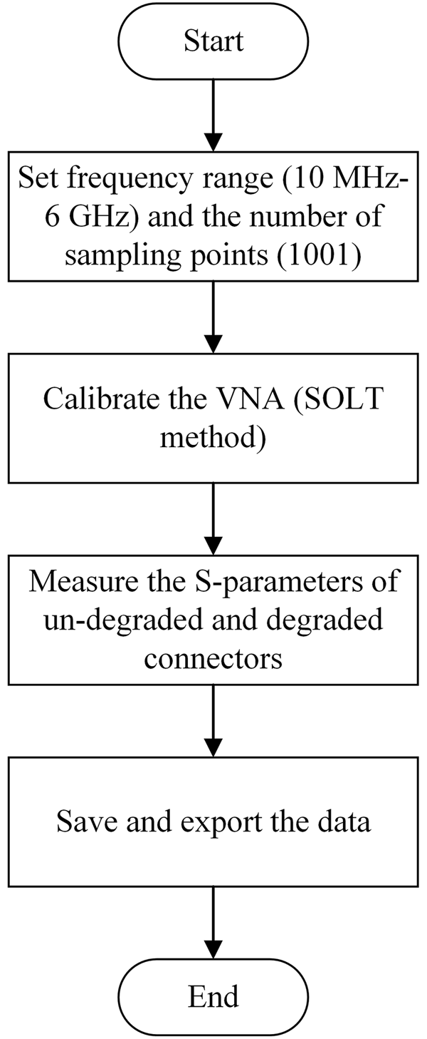
The S-parameters of connectors at un-degraded and different degradation conditions were obtained by experimental testing. As illustrated in Fig. 2, through two high-frequency test cables, the connector was connected to a vector network analyzer. The experimental process is depicted in Fig. 3. As shown in Fig. 4(a), with regard to the un-degraded case, the value of S11 is below −20 dB in the whole frequency band. The S11 parameter of the connectors at three different degradation levels is generally higher than that of the un-degraded connector, particularly at frequencies where the values nearly approach to 0 dB. This indicates an increase of signal reflections at the low-frequency band, affecting signal transmission. For the frequency range from 1.5 to 6 GHz, their S11 values are less than −15 dB, which means that the electromagnetic reflection of the signal transmission channel is minimal in high-frequency band. It can be seen from Fig. 4(b), with regard to the un-degraded case, the value of S21 is close to 0 dB. It can be regarded that there is almost no transmission loss in the measured frequency band, indicating that the un-degraded connector has good transmission performance. For the degraded, in the low-frequency band, the S21 values are less than −3 dB and the largest transmission loss will increase as the degradation level increases. For example, S21 values at the frequency point of 10 MHz are respectively −4.7, −10.3, and −30.2 dB for degradation levels 1, 2, and 3. This means that few electromagnetic waves are transmitted. For the frequency range from 10 MHz to 1 GHz, the S21 values of the three samples increase as the frequency increases. From the analysis of Fig. 4, it can be concluded that the signal transmission quality in the low-frequency band was mainly influenced by the connector degradation. The transmission path with the connector after severe degradation is open, and the impact on the signal transmission in the high-frequency band is less than that in low-frequency band.
High-frequency experimental setup.

S-parameter measurement process.

Measured S-parameters of connectors with un-degraded and different degradation levels. (a) S11 and (b) S21.

With the continuous improvement of signal transmission frequency, the electronic connector has been modeled and analyzed as a part of the transmission line. In this work, the application frequency band of the selected connector is from 10 MHz to 6 GHz, where the electromagnetic wavelength is relatively short. Therefore, the selected connectors were analyzed by using the transmission line theory in this work.
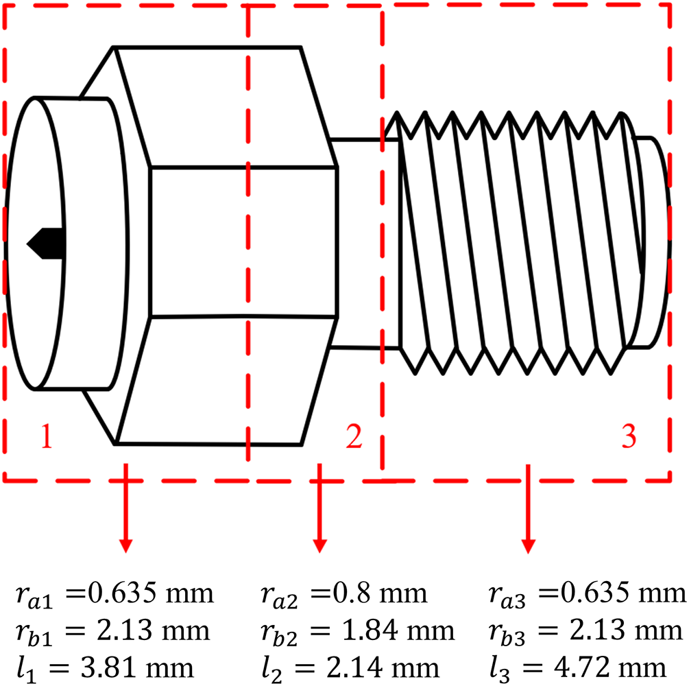
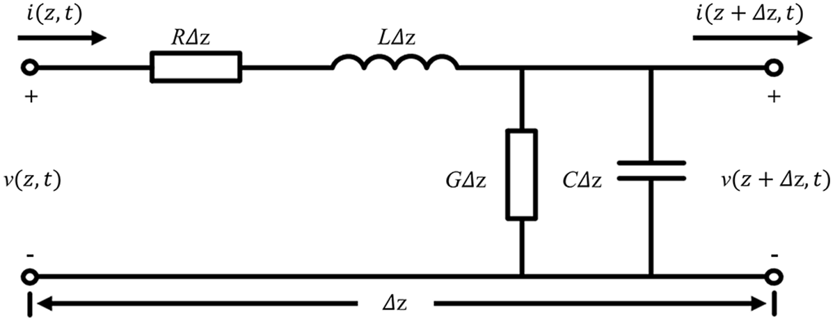
On the basis of the transmission line theory, the connector can be studied in segments. According to the structural differences between the inner conductor and the outer conductor, the connector can be divided into three segments. The sizes of each segment are shown in Fig. 5, where rai (i =1-3) and rbi (i =1-3) are the outer radius of the inner conductor and the inner radius of the outer conductor of each segment, respectively. li (i =1-3) is the length of each segment. The connector can be regarded as a uniform transmission line, since the structure of the inner conductor and the outer conductor has no changes for every segment. The distributed parameter circuit is illustrated in Fig. 6. In the interest of simplicity, the transmission line is regarded as lossless, which means that influences of the resistance R and the conductance G are neglected, and the electrical properties are completely determined by the distributed parameters C and L. The capacitance and inductance per unit length of the coaxial transmission line can be expressed as
 \begin{equation}{C_i} = \frac{{2\pi {\varepsilon _i}}}{{\ln \frac{{{r_{bi}}}}{{{r_{ai}}}}}}\end{equation}
Connector segment structure.

The section lumped circuit model of microwave transmission lines with distributed elements.

and
 \begin{equation}{L_i} = \frac{{{\mu _i}}}{{2\pi }}\ln \frac{{{r_{bi}}}}{{{r_{ai}}}}\end{equation}
where εi and μi are the dielectric constant and permeability of the dielectric material between the conductors in each segment, respectively. In addition, the number of LC sections in the model can be calculated as [Reference Bogatin22]
 \begin{equation}n \geqslant 10 \times BW \times TD\end{equation}
where BW represents the bandwidth of the n-section lumped-circuit model and TD represents the time delay of the transmission line. According to (1), (2), and (3), the equivalent circuit for the un-degraded connector can be developed, using the calculation results of each segment shown in Table 2.
Distributed parameters of a connector

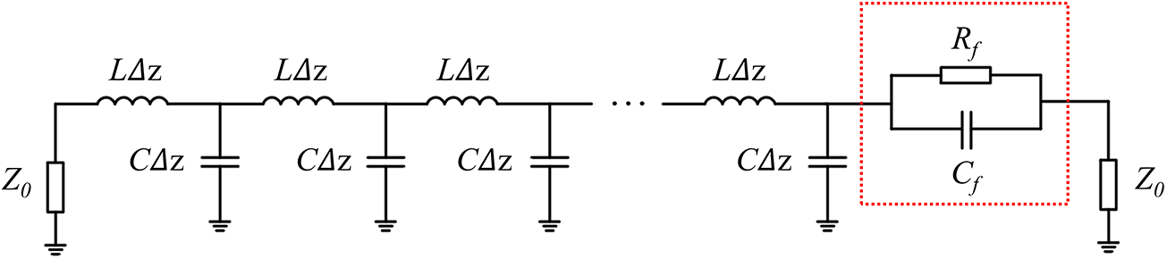
On the basis of the electrical contact theory, when two rough surfaces contact with each other, the two surfaces are not in complete contact, but form a peak contact. For the connector, the contact area will generate resistance effect, while the area that is not in contact will result in a capacitance effect. After the accelerated experiments, with the degraded contact surface, the contact area of the connector pin is covered by a layer of corrosion film, resulting in film resistance and film capacitance [Reference Ji, Gao, Flowers, Xie, Cheng and Jin1]. Since the thickness of the film is electrically small compared to the signal wavelength, it is reasonable to model it using a lumped RC network. As illustrated in Fig. 7, the equivalent circuit model of the degraded connector is constructed by adding a parallel connection of film resistance (Rf) and film capacitance (Cf) to the original circuit. Z0 represents the characteristic impedance of 50 Ω.
Equivalent circuit model of the degraded connector.

The film resistance and film capacitance were obtained by fitting the S-parameters of the three degraded connectors. As shown in Table 3, with the increase of degradation level, the film resistance increases and the film capacitance decreases. These results also indicate that the film resistance mainly affects the signal transmission in the low-frequency band, which is demonstrated by that the S21 value of degraded connectors is lower in the low-frequency band than that of the un-degraded connector. The film capacitance mainly affects the signal transmission in the high-frequency band, because of the capacitive coupling effect. Moreover, it can be found that the connector degradation has little effect on high-frequency signal transmission.
Film parameters of equivalent circuit model of degraded connectors

It can be seen from Fig. 8(a) that the S11 of the connectors at three different degradation levels is consistent with the S11 trend obtained from the measurement. As shown in Fig. 8(b), measurements and simulations are in good agreement at the low-frequency band. While in the high-frequency band, the S21 values obtained by the model are higher than that of the measurement, their trends are consistent and the differences are small, which proves that the model is accurate.
S-parameters obtained from the equivalent circuit model. (a) S11 and (b) S21.

Design of passive equalization
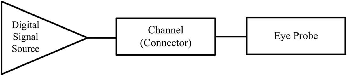
Study of high-speed signal transmission characteristics and equalization technology has important academic value, which is of significance to practical engineering applications. In this section, non-return to zero (NRZ) signal is selected for analysis and discussion of the deleterious impact of degraded RF coaxial connectors on high-speed digital signal transmission. Based on the equivalent circuit model, a passive equalization method for degraded connectors in high-speed interconnection system is proposed. The eye diagram shows a full opening with only two lumped elements. As demonstrated in Fig. 9, the digital signal transmission system includes three components, a digital signal source, the transmission channel and the eye probe. In simulation, a specific NRZ pseudo random binary sequence (PRBS) generated by the signal source is transmitted through the selected channel model, and the output eye diagram characteristics are obtained by the eye probe.
Simulation setup of digital signal transmission system.

Firstly, the simulation of high-speed digital signal transmission was conducted for the connectors before equalization. A 9th-order PRBS signal was generated by the digital signal source. In high-speed digital signal transmission, it is usually used to evaluate the transmission performance of the channel. The digital signal bit rate was 6 Gbps, the rise time and fall time were both 30 ps, and the signal amplitude levels 1 and 0 were 0.5 and −0.5 V, respectively. The internal resistance of the signal source and the signal receiver was set as 50 Ω, which matches the connector characteristic impedance.
As shown in Fig. 10, the four eye diagrams demonstrate varying degrees of eye opening, indicating that each connector can transmit signals, but the transmission performance is different. The corresponding eye diagram parameters are shown in Table 4. It can be seen that the transmission performance of the un-degraded connector is the best among all these channels. With increasing the degradation level, all eye diagram parameters deteriorate. This is mainly because the film resistance and film capacitance induced by the connector degradation. The eye height and signal-to-noise ratio (SNR) of the output signal of degraded connectors were significantly deteriorated. For degradation level 3, the eye height is only 0.071 V, and the eye opening factor is only 0.58. The degradation has little effect on the eye width. The jitter increased from 0.37 to 4.51 ps. These results are due to the fact that with the increase of degradation level, the increase of film resistance affects the transmission of low-frequency signals, thus affects the eye diagram at the receiver when transmitting digital signal. High-frequency signals are less affected.
Simulated eye diagrams of signal before equalization. (a) Un-degraded. (b) Degradation level 1. (c) Degradation level 2. (d) Degradation level 3.

Parameters of the simulated eye diagrams before equalization

Without using any equalization, eye diagrams of the digital signal through un-degraded and various degraded connectors were measured. High-speed experimental setup is shown in Fig. 11, where the connector specimen was connected to an arbitrary waveform generator (AWG) and an oscilloscope using test cables. Consistent with the simulation, a 9th-order PRBS signal with a signal rate of 6 Gbps was generated by the AWG. The rise time and fall time were both set to 0.18 UI. The signal amplitude levels 1 and 0 were 0.5 and −0.5 V respectively. The measured eye diagrams are shown in Fig. 12, and the parameters are listed in Table 5.
High-speed experimental setup.

Measured eye diagrams of signal before equalization. (a) Un-degraded. (b) Degradation level 1. (c) Degradation level 2. (d) Degradation level 3.

Parameters of the measured eye diagrams before equalization

All four eye diagrams show open eyes. However, as the degradation level increases, indicating attenuation of the signal transmission performance. According to the values provided in Table 5, the best eye height is 570.4 mV and the worst value is 22 mV. After degradation, the eye width decreased from 151.02 to 62.5 ps, and jitter also increased. The measurements show a consistent trend with the simulations, indicating that the corrosion film will cause attenuation of the received digital signal. In addition, the simulation results are better than the measurement results, which is mainly because the connectors were treated as lossless and the test cable losses were not considered in the simulation.
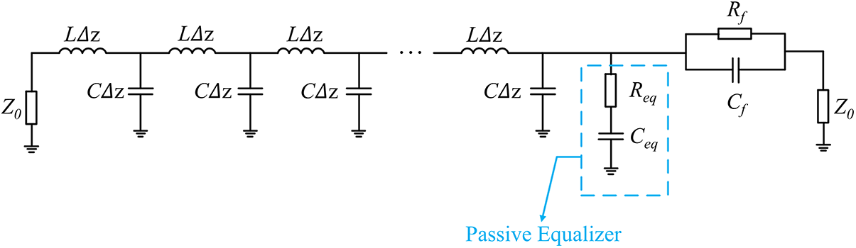
As shown in Fig. 13, a passive equalization method with resistance and capacitance in series is proposed, which can perfectly compensate the connector transmission loss caused by degradation. According to the electrical contact theory, film resistance and film capacitance can be introduced at the interface of degraded connector, affecting signal transmission. Therefore, these two factors should be concerned for designing the compensation equalizer. The transfer function of the interconnect channel with an equalizer can be described as [Reference Sun, Wen and Wu13]
 \begin{equation}H(s) = \frac{1}{{1 + \frac{{1 + s{C_{eq}}\left( {{R_{eq}} + {Z_0}} \right)}}{{1 + s{C_{eq}}{R_{eq}}}} \cdot \frac{{\left( {1 + {R_f}/{Z_0}} \right) + s{C_f}{R_f}}}{{1 + s{C_f}{R_f}}}}}\end{equation}
Equivalent circuit of the degraded connector with an RC equalizer.

where Req and Ceq are equalization resistance and capacitance respectively.
In pursuit of achieving an extremely flat frequency response, the transfer function of the channel should better be a constant. For the equalizer design, the resistance value should be
 \begin{equation}{R_{eq}} = \frac{{Z_0^2}}{{{R_f}}}\end{equation}
and the capacitance value should be
 \begin{equation}{C_{eq}} = {C_f}\frac{{Z_0^2}}{{\left( {{Z_0} + {R_{eq}}} \right){R_{eq}}}}.\end{equation}
Based on the accurate calculation by Rf and Cf, the resistance Req and capacitance Ceq in the passive equalizer can be specifically determined. Resistance and capacitance values of connector equalization designs for each degradation level are shown in Table 6. With the increase of degradation level, the equalization resistance decreases while the equalization capacitance increases.
Resistance and capacitance of the equalization circuit for degraded connectors

The S-parameters of three different degraded connectors after equalization are shown in Fig. 14, obtained from the equivalent circuit simulation. S-parameters become flat within a bandwidth range from 10 MHz to 6 GHz. S11 values remains −0.2, −3.1, −7.3 dB and S21 values are −5, −10, and −34 dB, respectively, for degradation levels 1, 2, and 3. Using this method, the transmitted signal will not be distorted but will experience amplitude attenuation.
Simulated S-parameters of connectors at different degradation levels after equalization. (a) S11 and (b) S21.

The connectors at three degradation levels after using passive equalization technology are simulated respectively. The signal settings are the same with that before using equalization. The eye diagrams of the simulation are shown in Fig. 15. Applying the passive equalization, eye diagrams achieve full opening, it can be indicated that the channel transmission performance of digital signal has been greatly improved. Inspection of Table 7 shows that the eye width after equalization remains unchanged at approximately 166 ps. And, the eye opening factor is more than 0.97, which indicating that the signal exhibits low jitter and noise. Although the eye opening factors of the three degraded connectors after equalization are all close to 1, the corresponding eye heights have significant numerical difference. This is because the use of passive equalization led to signal amplitude attenuation. As the resistance of the equalization circuit decreases, the eye height decreases and the SNR continues to decline.
Simulated eye diagrams of signal after equalization. (a) Degradation level 1. (b) Degradation level 2. (c) Degradation level 3.

Parameters of the simulated eye diagrams after equalization

After using the passive equalization, excellent eye openings were achieved for every condition, where the eye opening factor can be increased by 50%. Although the equalization will introduce inevitable amplitude attenuation to the system data transmission, this proposed equalizer still improves the channel transmission capability of high-speed signals with excellent performance.
To evaluate the practical equalization performance, as shown in Fig. 16, the equalizer was designed based on the equalization parameters listed in Table 6. The experiment was conducted using the same signal settings as before equalization, and the results are presented using the degradation level 1 case as an example. Figure 17 compares the eye diagrams, from which it can be seen that the eye diagram of the signal after equalization exhibits a significantly wider and clearer eye, with an eye opening similar to that of the un-degraded condition. Specifically, as shown in Table 8, the eye width increased from 148.79 to 153.65 ps, and the jitter was reduced, indicating suppressed signal distortion and improved signal quality. Although factors such as cable loss and component tolerances cause numerical deviations, the overall trend between experimental and simulation results remains consistent. This confirms that the proposed equalization method effectively compensates for the transmission loss caused by connector degradation and is both feasible and practically applicable, thereby validating its effectiveness.
The equalizer.

Comparison of eye diagrams. (a) Un-degraded. (b) Degradation level 1 before equalization. (c) Degradation level 1 after equalization.

Parameters of the measured eye diagrams

Conclusion
The performance of RF coaxial connector deteriorates when it operates in harsh environments, which will lead to degradation of signal transmission. With regard to the characterizations of the degraded connectors, this paper proposed a passive equalization method utilizing only an RC circuit, designed based on transmission line theory and electrical contact theory. For the degraded connector, using the above equalization can achieve an almost fully eye opening with zero jitter, where the eye opening factor is close to 1 and it increases by more than 50% compared with that before equalization. Insights from this equalization method provide a better understanding and analyzing guidance for the engineering design of high-speed interconnection systems, which requires equalization technology in harsh environments.
In this study, theoretical analysis, simulation verification, and experimental testing were employed to investigate the characteristics of degraded connectors. S-parameter analysis demonstrates that the degradation affects low-frequency performance more significantly than high-frequency performance, and it can be predicted that the eye diagram will be deteriorated more severely as the degradation level increases. An equivalent circuit model was developed. Based on the equivalent circuit model, it was verified that the proposed equalization method perfectly compensates for the signal transmission loss of film resistance and film capacitance caused by the degradation. The resistance and capacitance of the equalization circuit are specifically determined by (5) and (6), which can significantly enhance the eye diagram at the receiver, providing a near-ideal high-speed signal transmission. This method has the advantages of low cost and simple structure, and it is highly valuable for practical engineering applications in high-speed interconnection systems.
Acknowledgements
This work was supported in part by the National Key R&D Program of China under Grant No. 2022YFF0605904, and in part by the Specialized Scientific Research Projects of Chinese Institute of Electronics and Beijing Smart-chip Microelectronics Technology Co., Ltd.
Competing interests
The authors declare none.

Jiayu Liu received the B.S. degree in electronic science and technology from the Beijing University of Posts and Telecommunications (BUPT), Beijing, China, in 2023, where he is currently pursuing the Ph.D. degree in integrated circuit science and engineering. His research interests include high-frequency signal and high-speed data transmission, signal integrity, and electrical contact reliability.

Jinchun Gao received the B.S. and M.S. degrees from Beijing University of Chemical Technology, and the Ph.D. degree in electronic circuits and systems from Beijing University of Posts and Telecommunications, Beijing. From 2009 to 2010, she was a Visiting Scholar with the Center for Advanced Vehicle and Extreme Environment Electronics, Auburn University, Auburn, AL, USA. She is currently a Professor of electronic engineering at Beijing University of Posts and Telecommunications. Her research interests include electrical contact reliability and wireless communications.

Chaoyi Wang received the B.S. degree in electronic and information engineering from Xidian University, Xi’an, China, in 2020. He is currently working toward the Ph.D. degree in electronic science and Technology from the Beijing University of Posts and Telecommunications, Beijing, China. His research interests include high-speed data transmission, signal integrity, interconnect modeling, and electrical contact reliability.

Tianmeng Zhang received the B.S. degree in communication engineering from Yanshan University (YSU), Qinhuangdao, China, in 2021. She is currently pursuing the Ph.D. degree in integrated circuit science and engineering from the Beijing University of Posts and Telecommunications (BUPT), Beijing, China. Her research interests include electromagnetic compatibility, signal integrity, and electrical contact reliability.

Ziyang Zhang received the B.S. degree in electronic information engineering from North University of China (NUC), Taiyuan, China, in 2023. He is currently pursuing the Ph.D. degree in integrated circuit science and engineering with Beijing University of Posts and Telecommunications (BUPT), Beijing, China. His research interests include electromagnetic compatibility, signal integrity, and electrical contact reliability.

Yiming Chen received the B.S. degree in electronic information science and technology from the Beijing University of Posts and Telecommunications (BUPT), Beijing, China, in 2024, where she is currently pursuing the M.S. degree in integrated circuit science and engineering. Her research interests include signal integrity and electrical contact reliability.