Nomenclature
-
 ${V_T}$
.
-
speed of target
-
${V_M}$
-
speed of missile
-
${V_r}$
-
relative velocity component along the line-of-sight
-
${V_\lambda }$
-
relative velocity component normal to line-of-sight
-
${a_M}$
-
acceleration of missile
-
${a_{M\max }}$
-
maximum acceleration of missile
-
${a_T}$
-
acceleration of target
-
${a_{T\max }}$
-
maximum acceleration of target
-
$r$
-
relative distance between missile and target
-
${t_{{\rm{imp}}}}$
-
impact time


Greek symbol
-
$\lambda $
-
line-of-sight angle
-
${\lambda _d}$
-
desired line-of-sight angle
-
${\sigma _M}$
-
look angle of missile
-
${\sigma _{M\max }}$
-
maximum look angle of missile
-
${\sigma _T}$
-
look angle of target
-
${\gamma _M}$
-
flight-path angle of missile
-
${\gamma _T}$
-
flight-path angle of target
-
${\theta _{{\rm{imp}}}}$
-
impact angle
-
${\theta _d}$
-
desired impact angle


1.0 Introduction
Traditionally, a guidance law aims to ensure target interception with the smallest possible miss distance, while also minimising energy consumption to extend operational range. However, such objectives alone are often insufficient to guarantee target defeat in modern combat. Warships are equipped with close-in weapon systems (CIWS) [Reference Tang, Wang, Jia, Hu and Ma1] that engage incoming missile warheads; consequently, anti-ship missiles must strike warships at a specified impact angle to defeat or evade these defenses. For anti-tank missiles, the missile should strike the vehicle’s relatively thin top armor at an angle close to normal to the horizontal plane. Imposing an impact angle constraint is also an effective strategy for anti-air missiles because it determines the engagement geometry and influences the resulting damage mechanisms [Reference Hu, Cao, Han and Xin2–Reference Yun, Song and Pei4].
Because of the importance of efficiently engaging targets, numerous studies have extensively investigated various impact angle control guidance (IACG) laws. Wang et al. [Reference Wang, Dong, Wang and Shan5] investigated an IACG law using the state-dependent Riccati equation (SDRE) method, which can be tuned by modifying its weighting factors. Lee and Seo [Reference Lee and Seo6] examined the physical implications of optimal guidance laws for stationary targets to enhance readers’ understanding. A unified cooperative guidance framework was proposed in Ref. [Reference Jianbo and Shuxing7], enabling multiple missiles to coordinate an attack on a single stationary target through a combination of centralised and decentralised communication topologies. A combined model for missile guidance and control is developed to account for system uncertainties, which encompass modelling errors, aerodynamic parameter variations and external disturbances. The stationary nature of targets simplifies their positional prediction, making the prediction process more susceptible to countermeasures such as interceptors or electronic jamming.
To engage a manoeuvring target while achieving a specified impact angle, Zhang et al. [Reference Zhang, Shengjing and Jie8] provided a fast fixed time nonsingular terminal sliding mode (FFTNTSM). The method demonstrated the ability to achieve system stabilisation within a finite time, independent of initial states and without encountering singularities. In Xiong et al. [Reference Xiong, Wei, Zhao, Xiong, Wang and Zhou9], an optimal control-based guidance law incorporating terminal constraints is formulated for engaging a manoeuvring target. The proposed approach can reduce the initial acceleration command and increase terminal velocity. The study in Ji et al. [Reference Ji, Liu, Song and Zhao10] introduced an innovative time-varying sliding mode guidance strategy designed to counter manoeuvring targets with uncertain acceleration profiles. Ming et al. [Reference Ming, Wang and Sun11] presented an integrated guidance and control (IGC) approach utilising non-singular terminal sliding mode control (NTSMC), where an extended state observer was employed to estimate unknown target acceleration and aerodynamic uncertainties. Chen et al. [Reference Chen, Chen, Liu and Cheng12] proposed a three-dimensional (3-D) cooperative guidance law that leverages fixed-time convergence to prevent performance degradation. Extending this work, a finite-time convergent nonlinear guidance law based on sliding mode control was proposed in Biswas et al. [Reference Biswas, Maity and Kumar13] to intercept different motions of target. However, this method is potentially susceptible to singularities when the elevation angle approach
 $\pi /2$
. Although the aforementioned studies have demonstrated effectiveness in intercepting manoeuvring targets at specified angles, they still face limitations such as significant impact angle deviations and increased miss distances, and are not applicable to targets that exhibit multiple motion states simultaneously. Guidance performance can deteriorate if the initial launch parameters (e.g., heading, velocity) are not properly aligned with the optimal attack trajectory, necessitating additional corrective manoeuvres.
Employing advantage of the IACG laws allows the missile to intercept the target at desired impact angle, which can incapacitate the defensive system. However, in practice, sensor systems with constrained fields of view (FOV), such as strapdown seekers, may lose lock on the intended target [Reference Kim and Kim14]. A two-stage guidance scheme for a stationary or slowly moving target with the field-of-view constraint was designed in Ai et al. [Reference Ai, Wang, Yu and Shen15]. The guidance law can accomplish salvo attack without using estimation of time-to-go. The authors in Kim et al. [Reference Kim, Lee and Kim16] proposed an IACG with seeker’s FOV limit based on the sliding mode control in a planar scenario. Their approach requires bearing-only measurements because it does not use relative distance or line-of-sight (LOS) rate information. Similar guidance law was devised in Sheng et al. [Reference Sheng, Zhang and Xia17], which combined fractional-order theory with sliding-mode control. The proposed method was validated by Monte Carlo simulations in two-dimensional and three-dimensional engagement scenarios, demonstrating improved robustness to random noise. In the literature, most studies achieve the desired impact angle under FOV constraints for stationary or slowly moving targets [Reference Chen, Wang, Wang, Shan and Xin18–Reference Ran, Qiuqiu, Wangchun and Yijie22], and only a few studies address manoeuvring targets. Moreover, existing guidance laws may not guarantee accurate performance in the presence of unknown target acceleration [Reference Wang, Wang, Cui, Li and Liu23, Reference Wang, Lee, Liu and Tahk24].
Typical design methodology for IACG laws comprises three steps: The first term is to model the engagement kinematics. The second term is the traditional homing guidance problem with impact angle control, considering the engagement kinematics. The final term is to prove the proposed approach can intercept the target with various motions. When the target manoeuvre is assumed known or partially known, an extended state observer is often employed to estimate the target’s acceleration. State observers are extensively utilised in the literature to estimate target manoeuvre characteristics, providing an effective means to mitigate uncertain disturbances and enhance control precision. However, in practical applications, challenges such as measurement noise in output signals and limitations imposed by the control sampling frequency necessitate well-designed, real-time disturbance/perturbation observer. This observer must be carefully optimised to balance convergence speed, estimation accuracy and robustness.
Unlike other IACG laws that address various target motions in the studies mentioned above, the proposed guidance law referred to as IACG-FOV, inspired by these works, offers the following contributions:
-
1. The proposed method removes the requirement for target acceleration measurements by treating unknown acceleration as a disturbance, acknowledging the difficulty of measuring target acceleration in real engagements. This approach improves the missile’s robustness against target manoeuvres.
-
2. The proposed law enables the missile to intercept the target at a prescribed impact angle while enforcing the FOV constraint throughout the engagement, taking practical implementation into account. The guidance law presented here can intercept targets moving in stationary, constant-speed or manoeuvring trajectories, while achieving any desired impact angle.
-
3. The preliminaries assume constant missile speed, which is reasonable over short time horizons when airframe characteristics remain relatively unchanged. However, over longer engagements missile speed and other characteristics can vary significantly. To address this, the paper validates the proposed guidance law using a realistic interceptor model with speed variations. The superiority and robustness of the method are demonstrated through numerical simulations and theoretical analysis, and compared with state-of-the-art approach reported in Kim and Kim [Reference Kim and Kim14] and Xiong et al. [Reference Xiong, Wang, Liu, Wang and Chen25].
The remainder of this paper is structured as follows: Section 2 establishes the engagement kinematics and outlines the overall guidance strategy. Section 3 discusses the relationship between the impact angle and the LOS angle, along with the design process of the proposed guidance law. Section 4 substantiates the stability, look angle dynamics and capturability of the proposed guidance approach. Section 5 presents simulation results that evaluate the performance of the proposed guidance law under multiple engagement scenarios, including different target motions, a realistic interceptor model with speed variations, and comparative experiments. Section 6 provides a summary of conclusions and future work.
2.0 Problem formulation
This section outlines the derivation of the engagement kinematics between the missile and the target, as well as the homing problem, considering impact angle control and FOV constraints. Before presenting the problem formulation, the following general assumptions are typically made in the design of the guidance law [Reference Chen, Wu and Wang26, Reference Singh and Hota27]:
Assumption 1: The missile and target are modeled as point masses moving at constant velocities, with the missile having a speed advantage over the target.
Assumption 2: The accelerations of both the missile and target are assumed to be perpendicular to their respective velocities. The target’s acceleration is unknown but bounded.
Assumption 3: When the missile’s angle-of-attack is sufficiently small to be neglected, the missile’s look angle approximates the lead angle.
In missile guidance problems, accounting for the actual shape and aerodynamic properties of the missile and target adds complexity to the modelling process in Assumption 1. Treating both as point masses allows for a simpler and more efficient analysis. This assumption is reasonable for short-duration engagements where changes in velocity are negligible. Assumption 2 implies that both the missile and target primarily undergo uniform curvilinear motion, meaning they change direction through normal acceleration rather than adjusting speed via tangential acceleration. In Assumption 3, when the angle of attack is negligible, the missile’s body axis aligns with its flight path. Consequently, the look angle becomes geometrically congruent with the lead angle. It allows the guidance command to be formulated directly based on the readily measurable look angle. These assumptions are commonly used in missile guidance studies, making theoretical derivations and simulations more practical while still capturing essential engagement dynamics.
2.1 Engagement kinematics
While the general problem of missile guidance against a moving target is inherently three-dimensional, the present study adopts a planar engagement model. To formulate the impact angle control and FOV constrained guidance law, a planar engagement geometry is shown in Fig. 1. The velocity, acceleration, look angle and flight-path angle are denoted by
 ${V_{( \cdot )}}$
,
 ${a_{( \cdot )}}$
,
 ${\sigma _{( \cdot )}}$
, and
 ${\gamma _{( \cdot )}}$
. The
 $M$
and
 $T$
represent the missile and target.
 $\,r$
and
 $\lambda $
represent distance and LOS angle between them, respectively. The missile-target motion equations are expressed as follows:
 \begin{align} {\dot x_M} &= {V_M}\cos {\gamma _M}\quad{\dot \gamma _M} = {V_M}\sin {\gamma _M}\quad{\dot \gamma _M} = {a_M}/{V_M} \\[-4pt] \nonumber \end{align}
 \begin{align} {\dot x_T} &= {V_T}\cos {\gamma _T}\quad{\dot \gamma _T} = {V_T}\sin {\gamma _T}\quad{\dot \gamma _T} = {a_T}/{V_T} \\[10pt] \nonumber \end{align}
Planar engagement geometry.

The engagement kinematics equations can be formulated as follows:
 \begin{align} \dot r &= {V_r} = {V_T}\cos {\sigma _T} - {V_M}\cos {\sigma _M} \\[-5pt] \nonumber \end{align}
 \begin{align} \dot \lambda &= {V_\lambda }/r = ({V_T}\sin {\sigma _T} - {V_M}\sin {\sigma _M})/r \\[-4pt] \nonumber \end{align}
 \begin{align} {\sigma _M} &= {\gamma _M} - \lambda \\[-5pt] \nonumber\end{align}
 \begin{align} {\sigma _T} &= {\gamma _T} - \lambda \\[10pt] \nonumber\end{align}
where
 ${V_r}$
and
 ${V_\lambda }$
are relative velocity component along and normal to the LOS, respectively.
2.2 Guidance strategy
To ensure the missile intercepts the target with zero miss distance, desired impact angle and FOV constrained, the mathematical expressions of guidance strategy are
 \begin{align} r({t_{{\rm{imp}}}}) &= 0 \\[-5pt] \nonumber\end{align}
 \begin{align} {\theta _{{\rm{imp}}}} = {\gamma _T}({t_{{\rm{imp}}}}) - {\gamma _M}({t_{{\rm{imp}}}}) &= {\sigma _T}({t_{{\rm{imp}}}}) - {\sigma _M}({t_{{\rm{imp}}}}) \\[-5pt] \nonumber\end{align}
 \begin{align} \left| {{\sigma _M}(t)} \right| &\le {\sigma _{M\max }} \le \frac{\pi }{2}, t \in [0,{t_{{\rm{imp}}}}] \\[10pt] \nonumber\end{align}
where
 ${t_{{\rm{imp}}}}$
is the impact time, which is defined as the time required for the missile to intercept the target along a nominal trajectory [Reference Chen and Wang28].
 ${\theta _{{\rm{imp}}}}$
denotes the impact angle, which is time varying and calculated by each iteration.
Given that the velocity ratio
 ${V_T}/{V_M}$
is significantly less than 1 based on Assumption 1, we can further assume that
 $\sin {\sigma _M}\left( 0 \right) - \left( {{V_T}/{V_M}} \right)\sin {\sigma _T}\left( 0 \right) \lt \sin {\sigma _{M\max }} + {\varepsilon _1}$
.
 ${\sigma _{M\max }}$
represents the maximum look angle, which is a positive constant. The
 ${\sigma _{M\max }}$
is designed to satisfy the following [Reference Wang, Zhang and Wu29]:
 \begin{align}\cos {\sigma _{M\max }} \ge {V_T}/{V_M} + {\varepsilon _1} \end{align}
where
 ${\varepsilon _1}$
is a positive constant.
3.0 Guidance law against a manoeuvring target
This section introduces the design methodology for impact angle control with FOV constrained guidance law. A nonsingular sliding mode control-based solution is developed by leveraging the inherent relationship between the impact angle and the LOS angle.
3.1 Impact and LOS angle
To derive the relationship between the impact and LOS angles, the planar engagement geometry shown in Fig. 1 must be considered. When the missile and target are on a collision course, the component of their relative velocity normal to the LOS is zero, i.e.,
 ${V_T} = 0$
. According to Equations (4–6) and (8), the following equation can be derived:
 \begin{align}\cos {\sigma _{M\max }} \ge {V_T}/{V_M} + {\varepsilon _1} \end{align}
Based on Equation (11),
 $\lambda ({t_{{\rm{imp}}}})$
is independent of
 ${V_T}/{V_M}$
.
 $\lambda ({t_{{\rm{imp}}}})$
has a one-to-one correspondence to the
 ${\theta _{{\rm{imp}}}}$
. The following equation can be obtained:
 \begin{align}\lambda ({t_{{\rm{imp}}}}) = {\gamma _T}({t_{{\rm{imp}}}}) - \arctan \frac{{\sin {\theta _{{\rm{imp}}}}}}{{\cos {\theta _{{\rm{imp}}}} - {V_T}/{V_M}}} \end{align}
In order to establish the desired impact angle
 ${\theta _d}$
at the interception, the authors in Kim and Kim [Reference Kim and Kim30] developed a feasible method is to establish the relation between the
 ${\lambda _d}$
and
 ${\theta _d}$
at the beginning. Equation (12) can be expressed as:
 \begin{align}{\lambda _d} = {\gamma _T} - \frac{{\sin {\theta _d}}}{{\cos {\theta _d} - {V_T}/{V_M}}} \end{align}
Further, in order to guarantee the target remains within the missile’s FOV, the desired LOS angle
 ${\lambda _d}$
in Equation (13) is rewritten as follows:
 \begin{align}{\lambda _d} = \left\{ {\begin{array}{*{20}{l}}{{\gamma _T} - \dfrac{{\sin {\theta _d}}} {{\cos {\theta _d} - {V_T}/{V_M}}},} &\quad {0 \le {\theta _d} \lt 90}\\[12pt] {{\gamma _T} - \dfrac{{\sin {\theta _d}}}{{\cos {\theta _d} - {V_T}/{V_M}}} - \pi ,} &\quad {90 \le {\theta _d} \le 180}\end{array}} \right. \end{align}
Differentiating Equation (14) with respect to time yields
 \begin{align}{\dot \lambda _d} = {\dot \gamma _T} = {a_T}/{V_T} \end{align}
where
 ${\theta _d}$
,
 ${V_T}$
and
 ${V_M}$
are constants. Substituting Equation (2) into the equation above yields the result.
3.2 Guidance law design
A suitable switching surface and guidance law is proposed to impose the impact angle control with FOV constrained. Consider intercepting a manoeuvreing target with unknown acceleration, we can intuitively define the error
 ${x_1}$
and constraint
 ${x_2}$
as follows:
 \begin{align} {x_1} = \lambda - {\lambda _d} \\[-5pt] \nonumber\end{align}
 \begin{align} {x_2} = {V_\lambda } \\[10pt] \nonumber \end{align}
Substituting Equations (3) and (4) into the time derivative of
 ${x_1}$
and
 ${x_2}$
yields the following:
 \begin{align} &\qquad\quad{\dot x_1} = (1/r){x_2} \\[-5pt] \nonumber\end{align}
 \begin{align} {\dot x_2} &= (\!- \dot r/r){x_2} - {a_M}\cos {\sigma _M} + {a_T}\cos {\sigma _T} \\[10pt] \nonumber\end{align}
Consider the system
 ${\dot x_2}$
,
 ${a_M}$
can be regarded as the control input of missile. It is possible to make
 $({x_1},{x_2})$
converge to
 $(0,0)$
before the missile intercepts the target by rationally designing
 ${a_M}$
, and the constraints in Equations (7) and (8) are satisfied. A sufficient condition for satisfying Equation (9) based on Equation (4) is given by
 \begin{align}\left| {{x_2}} \right| \le {k_1}, {k_1} = {V_M}\sin {\sigma _{M\max }} - {V_T} \end{align}
where
 ${k_1}$
is positive controller gain.
To characterise the FOV constraint through Equation (20) is reasonable. The goal of the guidance law design can be recharacterised as: design a guidance law based on Equation (19) to make the system
 ${\dot x_2}$
converge to the zero in finite time while satisfying the state constraints defined by Equation (20).
From Equations (16) and (17), the following switching surface can be used to achieve the desired tasks:
 \begin{align} s = w(t){x_1} + {x_2} \\[-5pt] \nonumber \end{align}
 \begin{align} 0 \lt {\varepsilon _2} \le w(t) \lt {k_1}/\left| {{x_1}} \right| \\[-5pt] \nonumber \end{align}
 \begin{align} w(t) = \frac{{{k_1}}}{{\sqrt {x_1^2 + \alpha } }} \\[10pt] \nonumber\end{align}
where
 $w(t)$
is a continuous time-varying function and
 ${\varepsilon _2}$
is a positive constant.
 $\alpha $
is a guidance parameter, which is chosen to satisfy
 $0 \lt \alpha \lt 1$
.
Substituting Equations (16–19) into the time derivatives of Equation (21) yields the following:
 \begin{align} \dot s & = {k_1}\left[ {\dfrac{{{{\dot x}_1}}}{{{{(x_1^2 + \alpha )}^{1/2}}}} - \dfrac{{x_1^2{{\dot x}_1}}}{{{{(x_1^2 + \alpha )}^{3/2}}}}} \right] + {{\dot x}_2} \nonumber \\[8pt] & = \dfrac{{{k_1}\sigma }}{{{{\left[ {{{(\lambda - {\lambda _d})}^2} + \alpha } \right]}^{3/2}}}}\left(\dot \lambda - \dfrac{{{a_T}}}{{{V_T}}}\right) - \dot r\dot \lambda - {a_M}\cos {\sigma _M} + {a_T}\cos {\sigma _T} \nonumber \\[8pt] & = \left\{ { - \dot r + \dfrac{{{k_1}\alpha }}{{{{\left[ {{{(\lambda - {\lambda _d})}^2} + \alpha } \right]}^{3/2}}}}} \right\}\dot \lambda - {a_M}\cos {\sigma _M} + \left\{ {\cos {\sigma _T} - \dfrac{{{k_1}\alpha }}{{{V_T}{{\left[ {{{(\lambda - {\lambda _d})}^2} + \alpha } \right]}^{3/2}}}}} \right\}{a_T} \end{align}
Based on Equation (24), the guidance law for a manoeuvring target with unknown acceleration can be derived as follows:
 \begin{align} {a_M} &= \left\{ {{V_M} - \dfrac{{{V_T}\cos {\sigma _T}}}{{\cos {\sigma _M}}} + \dfrac{{{k_1}\alpha }}{{\cos {\sigma _M}{{\left[ {{{(\lambda - {\lambda _d})}^2} + \alpha } \right]}^{3/2}}}}} \right\}\dot \lambda \nonumber \\[8pt] &\quad + \left\{ {{k_2} + \left| {\dfrac{{{k_1}\alpha \dot \lambda }}{{\cos {\sigma _M}{{\left[ {{{(\lambda - {\lambda _d})}^2} + \alpha } \right]}^{3/2}}}} - \dfrac{{{V_T}\cos {\sigma _T}\dot \lambda }}{{\cos {\sigma _M}}}} \right|{V_M}\cos {\sigma _{M\max }}} \right\}\dfrac{{{\rm{sgmf}}(s)}}{{\cos {\sigma _M}}} \end{align}
 \begin{align}{\rm{sgmf}}(s) = \left\{ {\begin{array}{*{20}{l}}{ - \dfrac{1}{{2{\beta ^3}}}{s^3} + \dfrac{3}{{2\beta }}s,} &\quad {\left| s \right| \le \beta }\\[10pt] {{\mathop{\rm sgn}} (s),} &\quad {\left| s \right| \gt \beta }\end{array}} \right. \end{align}
where controller gain
 ${k_2}$
and guidance parameter
 $\beta $
are selected as
 ${k_2} \gt 0$
and
 $0 \lt \beta \lt 1$
, respectively. From Equation (26), the sigmoid function
 ${\rm{sgmf}}( \cdot )$
is continuous differentiable with the following bounds:
 \begin{align}\begin{array}{*{20}{c}}{\left| {{\rm{sgmf}}(s)} \right| \le 1,} & {\left| {\dfrac{{{\rm{d(sgmf}}(s){\rm{)}}}}{{ds}}} \right|}\end{array} \le \dfrac{3}{{2\beta }} \end{align}
Since achieving sliding mode
 $s = 0$
allows the missile to intercept the unknown manoeuvring target at the desired impact angle while maintaining FOV constraints, the subsequent Section 4 is dedicated to a formal stability analysis and comprehensive examination of the proposed guidance law.
4.0 Analysis of the proposed guidance law
Since achieving sliding mode allows the missile to intercept the unknown manoeuvring target at the desired impact angle while maintaining FOV constraints, as demonstrated in Subsection 3.1, we will substantiate the stability and analyse the proposed guidance law in Section 4.
4.1 Stability analysis
To verify whether the proposed method allows the missile to intercept the target under the desired constraints, a stability analysis of the guidance law is necessary. We now consider the Lyapunov candidate function as follows:
 \begin{align}V = \frac{1}{2}{s^2} \end{align}
Substituting the guidance law from Equation (25) into the time derivative of Equation (28) results in:
 \begin{align}\dot V &= \left\{ { - \dot r + \dfrac{{{k_1}\alpha }}{{{{\left[ {{{(\lambda - {\lambda _d})}^2} + \alpha } \right]}^{3/2}}}}} \right\}\dot \lambda s - {a_M}\cos {\sigma _M}s + \left\{ {\cos {\sigma _T} - \dfrac{{{k_1}\alpha }}{{{V_T}{{\left[ {{{(\lambda - {\lambda _d})}^2} + \alpha } \right]}^{3/2}}}}} \right\}{a_T}s \nonumber \\[10pt] &= \left\{ { - {k_2} + \dfrac{{{k_1}\alpha }}{{{{\left[ {{{(\lambda - {\lambda _d})}^2} + \alpha } \right]}^{3/2}}}}} \right\}\dot \lambda s - \left\{ {{V_M} - \dfrac{{{V_T}\cos {\sigma _T}}}{{\cos {\sigma _M}}} + \dfrac{{{k_1}\alpha }}{{\cos {\sigma _M}{{\left[ {{{(\lambda - {\lambda _d})}^2} + \alpha } \right]}^{3/2}}}}} \right\}\dot \lambda \cos {\sigma _M}s\nonumber \\[10pt] &+ \left\{ {{k_2} + \left| {\dfrac{{{k_1}\alpha \dot \lambda }}{{\cos {\sigma _M}{{\left[ {{{(\lambda - {\lambda _d})}^2} + \alpha } \right]}^{3/2}}}} - \dfrac{{{V_T}\cos {\sigma _T}\dot \lambda }}{{\cos {\sigma _M}}}} \right|{V_M}\cos {\sigma _{M\max }}} \right\}\dfrac{{{\rm{sgmf}}(s)}}{{\cos {\sigma _M}}}\cos {\sigma _M}s\nonumber \\[10pt] &+ \left\{ {\cos {\sigma _T} - \dfrac{{{k_1}\alpha }}{{{V_T}{{\left[ {{{(\lambda - {\lambda _d})}^2} + \alpha } \right]}^{3/2}}}}} \right\}{a_T}s\nonumber \\[10pt] &= - \left\{ {{k_2} + \left| {\dfrac{{{k_1}\alpha \dot \lambda }}{{\cos {\sigma _M}{{\left[ {{{(\lambda - {\lambda _d})}^2} + \alpha } \right]}^{3/2}}}} - \dfrac{{{V_T}\cos {\sigma _T}\dot \lambda }}{{\cos {\sigma _M}}}} \right|{V_M}\cos {\sigma _{M\max }}} \right\}{\rm{sgmf}}(s)s\nonumber \\[10pt] &+ \left\{ {\cos {\sigma _T} - \dfrac{{{k_1}\alpha }}{{{V_T}{{\left[ {{{(\lambda - {\lambda _d})}^2} + \alpha } \right]}^{3/2}}}}} \right\}{a_T}s\nonumber \\[10pt] &\le - {k_2}{\rm{sgmf}}(s)s + \left( {1 + \dfrac{{{k_1}}}{{{V_T}\alpha }}} \right){a_T}s\nonumber \\[10pt] &\le \left[ {\left( {1 + \dfrac{{{k_1}}}{{{V_T}\alpha }}} \right){a_T} - {k_2}} \right]\left| s \right| \\[-10pt]\nonumber \end{align}
To ensure Equation (29) to be negative definite, the range of controller gain
 ${k_2}$
should be modified to satisfy
 ${k_2} \gt 1 + {k_1}{a_T}/{V_T}\alpha $
. Therefore, the homing and impact angle control with FOV constrained in Equations (7–9) can be satisfied under Equation (25).
4.2 Capability analysis
Theorem 1.
Consider Equations (10), (18) and (19) are valid, and
 ${t_s}$
attains sliding mode surface. If guidance system is on sliding mode
 $\left( {s = 0} \right)$
, then the conclusions
 $\left| {{x_2}} \right| \le {k_1}$
and
 $r({t_{{\rm{imp}}}}) = 0, {\theta _{{\rm{imp}}}} = {\theta _d}$
are valid.
Proof:
When
 $s = 0$
, based on Equation (21),
 \begin{align}\left| {{x_2}} \right| = \left| { - w(t){x_1}} \right| = w(t)\left| {{x_1}} \right| \le {k_1}/\left| {{x_1}} \right| \cdot \left| {{x_1}} \right| = {k_1} \end{align}
Further, based on Equations (3), (9) and (10),
 $\dot r$
is governed by the following dynamic equation:
 \begin{align}\dot r& \le - {V_M}\cos {\sigma _{M\max }} + {V_T} \nonumber \\[3pt]&\le - {V_M}({V_T}/{V_M} + {\varepsilon _1}) + {V_T}\nonumber \\[3pt]& = - {V_M}{\varepsilon _1}\nonumber \\[3pt] &\lt 0 \end{align}
Thus, as can be deduced from Equation (31),
 $r({t_s})$
is bounded.
 $\dot r$
is negative definite and there exists a negative upper definite bound. Furthermore, from the definition of the sliding mode variable in Equation (21),
 $s = 0$
is equivalent to
 ${x_2} = - w(t){x_1}$
.
By substituting
 ${x_2} = - w(t){x_1}$
into Equation (18), the time derivative of
 ${x_1}$
yields the following:
 \begin{align}{\dot x_1} = - w(t){x_1}/r \end{align}
Integrating Equation (32) on the interval
 $[{t_s},{t_{{\rm{imp}}}}]$
gives as
 \begin{align}{x_1}({t_{{\rm{imp}}}}) = {x_1}({t_s})\mathop {\lim }\limits_{t \to {t_{{\rm{imp}}}}} \exp \int_{{t_s}}^t {w(t)/rdt} = {x_1}({t_s})\exp (\! - \infty ) = 0 \end{align}
According to Equation (33), when
 $r({t_{{\rm{imp}}}}) = 0$
, the desired impact angle satisfies
 ${\theta _{{\rm{imp}}}} = {\theta _d}$
.
Once system Equations (18) and (19) are on the designed sliding mode, the error of impact angle and miss distance will converge to 0 and the FOV constraints will not be violated during this process.
Simulation parameters

5.0 Simulation results
This section validates the efficacy of the proposed IACG-FOV law through numerical simulations of a missile-target engagement. The performance analysis is systematically structured into four subsections to evaluate the guidance strategy’s advantages and robustness. Subsections 5.1 and 5.2 investigate various engagement scenarios against a nonmaoneuvreing and manoeuvring target with unknown acceleration. Subsection 5.3 assesses performance using a high-fidelity interceptor model with velocity variations. Finally, Subsection 5.4 presents a comparative analysis, benchmarking the proposed law against the SMC-FOV [Reference Kim and Kim14] referred as SMC-FOV and extended state observer NTSM-based IACG [Reference Xiong, Wang, Liu, Wang and Chen25] laws under identical conditions.
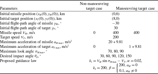
In all the simulations, the proposed approach uses the guidance parameters listed in Table 1. The simulation terminates when the relative distance falls below 1 meter, with a fixed time step of 0.001s throughout all engagement scenarios. In the guidance law parameters,
 $\alpha $
has a significant impact on the miss distance and impact angle error of the proposed guidance law. In order to achieve accurate guidance law effects, this article tested the range of values for
 $\alpha $
. Under the condition of ensuring intercepting the target, when
 $\alpha \gt 0.1$
, the error angle is relatively large. When
 $0\lt \alpha \lt 0.1$
, as the value of
 $\alpha $
decreases, the impact angle error gradually decreases. When
 $\alpha $
reaches 0.02, the system achieves optimal performance with both minimal miss distance and negligible impact angle error.
5.1 Nonmanoeuvring target
Different scenarios against a stationary and constant speed target are shown in this subsection. For the impact angle control with FOV constraints, the study evaluates five distinct desired impact angles (30, 60, 90, 120, 150) degrees under three different look angle constraints (70, 80, 90) degrees, comprehensively testing the guidance law’s performance envelope.
Figures 2 and 3 show the simulation results against a stationary and constant speed target for varying impact angle, subject to look angle constraints of
 ${70^ \circ }$
and
 ${80^ \circ }$
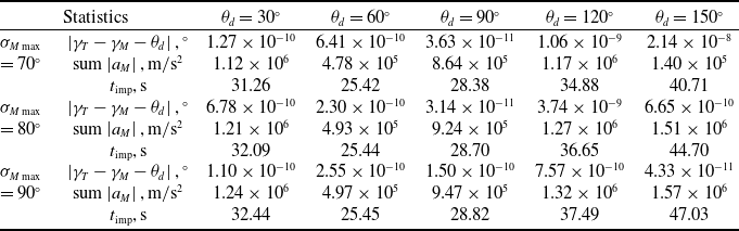
, respectively. The four figures illustrate flight trajectory, guidance command, look angle of missile and desired impact angle histories, respectively. Further, the performance of impact angle error, sum of the absolute values of missile acceleration and impact time are represented in Tables 2 and 3.
Performance for a stationary target

As shown in Figs 2(a) and 3(a), the proposed guidance law successfully intercepts the target while satisfying both the impact angle and miss distance requirements. Under the limitation of FOV, the missile trajectory exhibits a detour behaviour as the desired impact angle grows larger. The guidance command history in Figs 2(b) and 3(b) provides the result that the proposed guidance law produces a high-amplitude command signal during the initial engagement phase. This behaviour arises from a significant initial discrepancy between the desired and actual impact angles. The results indicate that adjusting the initial flight-path angle effectively mitigates this early-stage error, reducing the generation of large control commands and extending the missile flight range. Furthermore, with increasing desired impact angles, the moments of generating large control commands also increase in final phase. This is caused by homing constrained of desired impact angle and minimal miss distance. Figures 2(c) and 3(c) show that the missile’s look angle is less than the maximum look angle limitation of
 ${70^ \circ }$
and
 ${80^ \circ }$
during the flight trajectory, which proves theoretically in Subsection 5.2. As can be seen in Figs 2(d) and 3(d), the guidance law successfully achieves the desired impact angle at interception in all test cases.
Simulation results of against a stationary target. (a) Flight trajectory, (b) guidance command, (c) look angle of missile, (d) desired impact angle.

Tables 2 and 3 provide the quantitative performance against a nonmanoeuvring target. It should be noted that the obtained miss distances are influenced by numerical precision; values smaller than the target’s geometrical dimensions are considered acceptable. Furthermore, we also recorded the energy consumption of missile during the flight as
 ${\rm{sum}}\left| {{a_M}} \right|$
, which is an important indicator of the flight distance. Simulation results demonstrate that for a fixed desired impact angle, the terminal impact angle error grows proportionally with increasing maximum look angle, energy consumption of the missile and impact time increase as well. This is because as the maximum look angle decreases, the missile requires fewer control commands to intercept the target. In addition, for a given maximum look angle, larger desired impact angles require more substantial trajectory adjustments, resulting in greater terminal angle errors and extended engagement durations.
5.2 Manoeuvring target
Similar to the previous subsection, this paper simulates engagement scenarios comprising five desired impact angles (30, 60, 90, 120, 150) degrees and three look angle constraints (70, 80, 90) degrees against a manoeuvring target. The four figures in Fig. 4 illustrate flight trajectory, guidance command, look angle of missile and desired impact angle histories, respectively. Further, the performance for impact angle error, sum of the absolute values of missile acceleration and impact time are represented in Table 4.
Figure 4 demonstrates that the proposed guidance law successfully achieves both target interception and the desired impact angle while strictly maintaining look angle constraints. As shown in Fig. 4(a), these results indicate that the proposed method makes a detour, as the FOV constraint needs to be satisfied. Figure 4(b) proves that the proposed law acceleration commands all satisfy the constraints. Figure 4(c) shows that look angle consistently stays below the maximum constraint during the flight trajectory for manoeuvring target. The guidance law successfully achieves all commanded impact angles at interception across every test scenario, as shown in Fig. 4(d). Table 4 quantifies the performance of the proposed IACG law against manoeuvring targets, demonstrating the miss distance less than 1m with impact angle error less than 2.09 × 10⁻² and 2.46 × 10⁻² deg for the look angle limitation of
 ${\sigma _{M\max }} = {70^ \circ }$
,
 ${80^ \circ }$
and
 ${90^ \circ }$
against a manoeuvring target, respectively.
5.3 Realistic interceptor model
The analysed time span extends over several dozen seconds. Under real-world conditions, missile characteristics, such as velocity, undergo significant changes over such a duration. To verify the effectiveness and generalisability of the law in this paper under speed variations, a high-fidelity interceptor model incorporating realistic dynamics and constraints is conducted. The equations of motion for a point-mass interceptor over a flat-Earth, non-rotating reference frame are derived as:
Performance for a constant-velocity moving target

Simulation results of against a constant-velocity moving target. (a) Flight trajectory, (b) guidance command, (c) look angle of missile, (d) desired impact angle.

Simulation results of against manoeuvring target under the proposed guidance law. (a) Flight trajectory, (b) guidance command, (c) look angle of missile, (d) desired impact angle.

 \begin{align}\left\{ \begin{array}{l}{{\dot V}_M} = \dfrac{{T - D}}{m} - g\sin {\gamma _M}\\[8pt]{{\dot \gamma }_M} = \dfrac{{{a_M} - g\cos {\gamma _M}}}{{{V_M}}}\end{array} \right. \end{align}
 \begin{align}T = \left\{ {\begin{array}{*{20}{l}}{3300} \quad& {0 \le t \le 1.5}\\[3pt]{7500} \quad& {1.5 \lt t \le 8.5}\\[3pt]0 \quad& {t \gt 8.5}\end{array}} \right. \end{align}
 \begin{align}D = {D_0} + {D_i} \\[-10pt] \nonumber \end{align}
where
 $T$
represents the thrust exerted on the interceptor, primarily produced by its propulsion system.
 $D$
denotes the drag force opposing the interceptor’s movement due to air resistance. The terms
 ${D_0}$
and
 ${D_i}$
represent the zero-lift drag and induced drag coefficients, respectively.
 ${\dot \gamma _M}$
in Equation (1) is replaced with Equation (34). Detailed parameters can be found in Ref. [Reference Kumar, Rao and Ghose31].
Performance for manoeuvring target

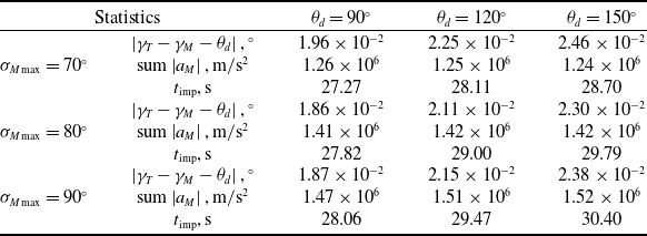
Different from the previous works, simulations are conducted with desired impact angle for 90 degrees – under three different look angle limitations of 70, 80 and 90 degrees. Each case involved intercepting a manoeuvring target under a realistic interceptor model. Figure 5 depicts the flight trajectory, guidance command, missile look angle and desired impact angle relative distance and missile speed, respectively. Additionally, Table 5 presents the performance metrics, including impact angle error, the sum of the absolute values of missile acceleration, and impact time.
Performance for manoeuvring target under a realistic interceptor model

As evidenced in Fig. 5(a) and 5(b), all evaluated guidance laws successfully intercept the manoeuvreing target while maintaining the missile’s acceleration commands within the prescribed limits. Furthermore, Fig. 5(c) and 5(d) demonstrates that the missile achieves the desired impact angle while adhering to the LOS angle constraint. The convergence of the missile-target distance to zero and the variation in missile velocity are illustrated in Fig. 5(e) and 5(f), respectively. Collectively, these results demonstrate the robustness of the proposed guidance law under conditions of time-varying velocity.
Simulation results for different look angle limitation against a manoeuvring target under a realistic interceptor model. (a) Flight trajectory, (b) guidance command, (c) look angle of missile, (d) desired impact angle, (e) relative distance, (f) missile speed.

Quantitative results in Table 5 further substantiate the law’s precision in simultaneously achieving interception, desired impact angles and LOS constraints. The law achieves precise target interception while simultaneously satisfying both desired impact angles and LOS constraints. Although larger desired impact angles lead to marginally increased impact angle errors, these deviations remain within acceptable limits. The increased angular demands necessitate trajectory adjustments, resulting in higher energy consumption and longer engagement durations due to the missile’s required detour to meet terminal constraints. This tradeoff between impact angle precision, energy efficiency and interception time is inherent to the guidance problem’s kinematic coupling.
5.4 Performance against comparative experiments
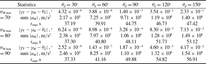
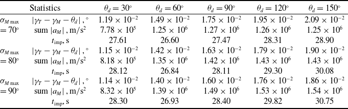
This subsection shows the performances of SMC-FOV and NTSM guidance laws against a manoeuvreing target. Similar to Subsection 5.2, we conducted simulations for five desired impact angles – 30, 60, 90, 120 and 150 degrees – under three look angle limitations of 70, 80 and 90 degrees. Figure 6 shows the flight trajectory, guidance command, missile look angle, and desired impact angle. Table 6 presents the results (including impact angle error, the sum of the absolute values of missile acceleration, and impact time) based on the SMC-FOV method, while Table 7 presents those based on the ANTSM method.
Note that the SMC-FOV guidance law cannot achieve desired impact angles of 30 or 60 degrees, while the NTSM method fails completely for 30 degrees impact angle scenarios. The proposed guidance law and SMC-FOV both achieve a miss distance of less than 1 meter, with impact angle errors below 2.09 × 10⁻² and 2.46 × 10⁻², respectively, for the look angle limitation of 70°, 80° and 90° against a manoeuvreing target, respectively. The proposed approach is more accurate and consumes less energy than SMC-FOV for manoeuvring targets, but the flight time is slightly longer. The proposed method successfully intercepts the target at desired impact angles ranging from 30° to 150°, achieving a miss distance of less than 1 meter while fully satisfying the FOV constraints. In contrast, the NTSM method exhibits a marked increase in impact angle error as the desired angle increases. Although NTSM maintains a larger but acceptable error bound of 1.97° for most cases, its performance deteriorates significantly at a 30° impact angle. Overall, the proposed method demonstrates superior performance compared to NTSM.
Performance for manoeuvring target based on SMC-FOV

Simulation results of against manoeuvring target with
 ${\sigma _{M\max }} = {70^ \circ }$
and
 ${\theta _d} = {150^ \circ }$
. (a) Flight trajectory, (b) guidance command, (c) look angle of missile, (d) desired impact angle.

Performance for manoeuvring target based on NTSM

6.0 Conclusions
This paper proposes a novel guidance law for controlling the impact angle under FOV constraints, designed to engage targets with unknown acceleration and diverse motion patterns. The research is motivated by the limitation of most existing guidance laws, which typically assume that target acceleration is known or partially known, relying on state observers for estimation. The inherent relationship between the impact angle and the LOS angle is formally derived, explicitly incorporating the FOV constraint. The theoretical analysis and proof demonstrate the effectiveness of the proposed methodology. Numerical simulations demonstrate that the proposed guidance law enables the missile to intercept the target with high precision, achieving a miss distance of less than 1 meter while strictly satisfying both the desired impact time and the seeker’s FOV constraints. Comparative results further confirm the superiority of the proposed law over existing methods in terms of accuracy and operational feasibility with impact angle error less than 2.33 × 10⁻¹ and 2.09 × 10⁻² deg for various motion of target, respectively. Future work will focus on developing a fixed-time interception guidance law with adaptive gain, aimed at achieving precise interception of high-speed manoeuvring targets under bounded unknown disturbances.
Acknowledgements
This work is supported by the National Natural Science Foundation (NNSF) of China under Grant 62273119.
Competing interests
The authors declare that they have no known competing financial interests or personal relationships that could have appeared to influence the work reported in this paper.