Introduction
Single-input single-output wireless systems can offer a high data rate either by increasing the transmit power or by increasing the bandwidth [Reference Proakis1]. But, considering the biohazards in the indoor environment, the transmit power is limited to 1 W [Reference Paulraj, Gore, Nabar and Bolcskei2]. However, increasing bandwidth at higher frequencies may result in an unstable non-line-of-sight link [Reference Paulraj, Gore, Nabar and Bolcskei2]. Multiple-input multiple-output (MIMO) systems, however, can eliminate these limitations. In this context, the compact layout of MIMO radiators accompanied by low mutual coupling is the major design challenge [Reference Jensen and Wallace3]. The last decade has seen the speedy evolution of modern wireless technologies including wideband MIMO/diversity techniques [Reference Sharawi4].
In the context of MIMO implementation, it is comparatively easy to observe limited mutual pairing at the base station, where segregation between the elements is always in the order of multiple wavelengths. However, in the case of portable devices, attaining a minimal mutual pairing is difficult due to the nominal inter-element separation. A keystone leading to the growth of the ultra-wideband (UWB) MIMO technology is the layout of the UWB MIMO radiator, which should essentially possess large impedance bandwidth and a minimal correlation [Reference Liu, Cheung and Yuk5] within a constrained design space. A large number of UWB MIMO radiators and diverse unlinking approaches to curb pairing among antenna elements have been proclaimed [Reference Malik, Patnaik and Machavaram6]. There are six broad classes in which mutual decoupling mechanisms are classified, which are namely the use of decoupling networks [Reference Gorai and Ghatak7], inscribed parasitic elements [Reference Roshna, Deepak, Sajitha, Vasudevan and Mohanan8], complementary split-ring resonators [Reference Khan, Capobianco, Asif, Anagnostou, Shubair and Braaten9], electromagnetic bandgap structures [Reference Ghosh, Tran and Le-Ngoc10], defected ground structures (DGSs) [Reference Banerjee, Karmakar, Ghatak and Poddar11] and neutralization lines (NLs) [Reference Diallo, Luxey, Thuc, Staraj and Kossiavas12]. The investigation of the standard literature depicts that the implementation of NLs for isolation enhancement in coplanar waveguide (CPW)-fed MIMO antennas remains unexplored. However, some significant contributions utilizing NLs for isolation improvements are discussed subsequently.
A two-element diversity antenna designed for wireless USB-Dongle application, incorporating NL for isolation enhancement is reported in [Reference Su, Lee and Chang13]. The introduction of an NL and the removal of a small portion of the ground structure cause an isolation enhancement of 10 dB, inside the frequencies of concern. Both DGS and a novel NL are employed in [Reference See, Abd-Alhameed, Abidin, McEwan and Excell14] between two crescent-shaped printed monopoles, to achieve high isolation of >−17 dB (between 2.4 and 4.2 GHz). The layout suggested in [Reference See, Abd-Alhameed, Abidin, McEwan and Excell14] attains a moderate realized gain ranging from 1 to 2.5 dBi. Next, the diversity antenna reported in [Reference Wang and Du15] adopts a pair of ground branches and an NL to attain high isolation. In this case, the deployment of the NL provides high mutual coupling reduction exclusively in the lower frequency bands (ranging between 1.7–2 GHz). The antenna reported in [Reference Wang and Du16] employs three NLs to reduce mutual coupling in the frequency range between 1.66–2.84 GHz. It suggests that, the impedance attributes of the radiator change with the introduction of multiple NLs. In [Reference Ban, Chen, Chen, Kang and Li17], a U-shaped NL is deployed to decouple the antenna elements of the hepta-band array for WWAN/LTE Smartphone utilization. A decoupled dual antenna system operating up to 3000 MHz is suggested in [Reference Wang and Du18] for LTE/WWAN smartphone usage. The design complexity of this antenna reported in [Reference Wang and Du18] is high, due to the use of crossed NLs between a pair of symmetric antenna elements. The isolation achieved in this contribution is ≤−10 dB. Furthermore, to acquire adequate impedance matching at the high-frequency bands, the crossed NLs require rigorous tuning, due to the presence of inductors. Finally, a compact UWB diversity antenna incorporating a broadband NL as well as providing high isolation of >22 dB (between 3.1 and 5 GHz) is proposed and studied in [Reference Zhang and Pedersen19].
The current standard literature on isolation improvement using NLs for MIMO antenna design reported in [Reference Su, Lee and Chang13–Reference Zhang and Pedersen19] is silent about the use of NL for isolation improvement in CPW-fed MIMO antennas operating across the complete ultra-wide spectrum (3.1–10.6 GHz). A few designs providing wideband isolation improvement exploring NLs are reported in [Reference See, Abd-Alhameed, Abidin, McEwan and Excell14] and [Reference Zhang and Pedersen19]. The design reported in [Reference See, Abd-Alhameed, Abidin, McEwan and Excell14] is fed by a Microstrip line and covers a wide frequency spectrum between 2.4–4.2 GHz with a large size of 40 × 90 mm2 whereas; the antenna reported in [Reference Zhang and Pedersen19] covers a frequency realm between 3.1–5 GHz (possessing a size of 35 × 33 mm2) and explores two thin cables to excite the two monopoles in the same mode. Moreover, the clearance area provided by the design reported in [Reference Zhang and Pedersen19] is just 48.4% of the total available area behind the antenna. Both these antennas using NLs for wideband isolation improvement cover the UWB spectrum partially. The exploration of the NL for broadband isolation improvement in the CPW-fed MIMO antenna is a big challenge. The only work proposed by the same authors is reported in [Reference Banerjee, Ghatak and Karmakar20]. The design reported in [Reference Banerjee, Ghatak and Karmakar20] explores a modified circular DGS to enhance the isolation in the lower bands (3.1–4.9 GHz) of the UWB spectrum at the cost of reduced impedance matching. However, a comparative analysis shows that the use of a modified Rectangular DGS allows better isolation improvement in the mid-frequency bands of the UWB spectrum and provides high impedance matching to the overall antenna. Additionally, in [Reference Banerjee, Ghatak and Karmakar20] a pair of rectangular slits is etched over the corresponding ground structures to cause band rejection attributes at the C-band (3.8–4.2 GHz) and Minkowski fractal slots are engraved over the radiators to enhance the isolation of the diversity antenna. The etching of slits in the ground structure as well as over the radiators leads to reduced gain, and efficiency, and distorts the radiation patterns of the antenna. The suggested construction is smaller in comparison to the design reported in [Reference Banerjee, Ghatak and Karmakar20] but, acquires a higher realized gain of 4.85 dBi, comparatively stable radiation patterns, and efficiency of 89.5%.
The suggested antenna explores a fractal NL for attaining high isolation across the complete UWB bandwidth (3.1–10.6 GHz). The space-filling property of the Hilbert fractal neutralization line (HFNL) is explored to integrate it into a small space. Additionally, the same fractal NL is tuned to cause an intended impedance mismatch, creating a standing wave, thereby causing band rejection attributes at 3.3 GHz. Finally, the gaps of the CPW feed line are further utilized to pair their magnetic field with a pair of cross-liked C-shaped resonators to allow band rejection at the Indian National Satellite System (INSAT) (4.5 GHz) band. The proposed decoupling network leads to a minimal inter-element spacing of 0.51 mm (edge to edge), which is the least, as reported in the standard literature. Additional isolation improvement structures like parasitic strips are also introduced for achieving an improvement in the level of isolation in the mid and high-frequency bands of the antenna [Reference Mak, Rowell and Murch21]. Moreover, the proposed antenna has more than 80% of the total available area behind the antenna as a clearance area for the RF circuits, where the circuits have less influence on the radiator performance.
Antenna design methodology
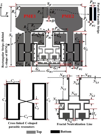
The outline of the recommended UWB MIMO monopole radiator is illustrated in Fig. 1. The suggested radiator is realized over a 1.6 mm thick FR4 substrate (dielectric constant ɛ r = 4.4, and a loss tangent tan δ = 0.02). Numerical verifications of the intended antenna are carried out by availing commercially obtainable EM software CST Microwave Studio™. The recommended antenna possesses an extensive bandwidth spanning from 2.64 to 12 GHz. The evolutionary steps and their S-parameters are illustrated in Fig. 2.
The optimum layout of the UWB MIMO radiator (mm). S W = 29.84, S L = 26.5, D = 0.51, R 1 = 8.5, R 2 = 10.75, R 3 = 2.5, R 4 = 1, R 5 = 0.41, P L = 10.88, P L1 = 4.92, P W1 = 0.275, P W2 = 0.125, P R1 = 0.5, P R2 = 6.65, G 1 = 0.48, G 2 = 5.71, G 3 = 2.91, G 4 = 1.01, G 5 = 10, G 6 = 1.4, G 7 = 4.67, G 8 = 0.3, GL = 14.5, G W1 = 15.6, G W2 = 4.05, F W = 2.8, F W1 = 0.3, C 1 = 8, C 2 = 3, C 3 = 7.5, C 4 = 2.61, C 5 = 0.8, C 6 = 2.30, C 7 = 2.55, N W = 0.33, N WS = 0.7, N L1 = 6.57, N L2 = 1.27, N L3 = 1.5, N L4 = 0.15, NLS = 0.7, N G = 0.3, N G1 = 2.89, H 1 = 3, H 2 = 1.5.

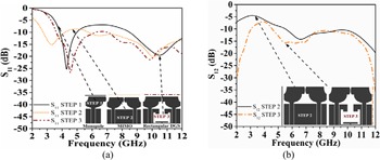
Modifications of S-parameters and collation of isolation improvement among initial steps of radiator design (a) S 11 characteristics (b) S 12 characteristics.

Design of CPW-fed monopole
The first stage of antenna evolution started with the design of a CPW-fed modified beveled half-elliptical monopole radiator [Reference Agrawall, Kumar and Ray22, Reference Ammann and Chen23] as shown in the inset of Fig. 2(a) (STEP 1). The suggested radiator is a modified elliptic patch owning major axis stretch = max (2R 2, 2R 1–3.5) and minor axis length = min (2R 2, 2R 1–3.5) [Reference Sarkar, Srivastava and Saurav24]. Here, S W is the width of the antenna and is equal to 29.8 mm. The ellipticity ratios are chosen to be 1.4 [Reference Agrawall, Kumar and Ray22] to attain a wide impedance bandwidth. The radiating modified half elliptic patch is fed by a 50 Ω CPW feed line of width F W = 2.8 mm. Additional beveled stub loading and slit loading are incorporated in the elliptical patch to further improve the impedance matching at higher frequencies (7–9 GHz).
Design of two element MIMO
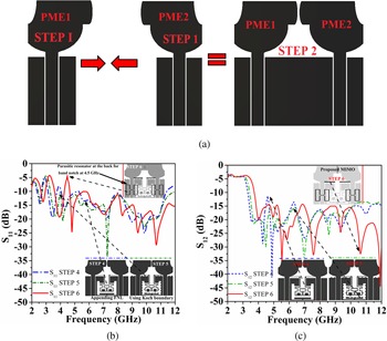
Figure 3(a) (STEP 2) illustrates the combination of the two identical monopoles already designed in STEP 1 (by sharing the common ground plane between them) to constitute the two-element diversity configuration. A direct enhancement in mutual pairing can be observed, as a result of sharing the same ground plane and near-field coupling (Fig. 2(b) (STEP 2)). The inter-element spacing is chosen to be 0.01λg (at 3.1 GHz) followed by parametric tuning, to achieve the least inter-element spacing with high isolation.
Modifications in the resonance characteristics of the UWB MIMO antenna with steps of antenna evolution. (a) Construction of the MIMO configuration. (b) Comparison of S 11 characteristics for final stages of antenna design. (c) Comparison of S 12 characteristics for final stages of antenna design.

Incorporation of neutralization line and defects in the ground plane for high isolation
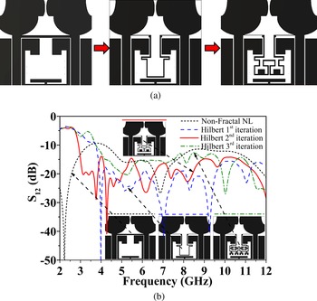
Isolation improvement is achieved by using defects in the ground plane along with the use of the neutralization line. In this design, a modified Rectangular DGS (as shown in Fig. 2(b) (STEP 3)) is made to achieve isolation improvement in the mid-frequency bands of the UWB spectrum (Fig. 2(b) (STEP 3)) and high impedance matching (Fig. 2(a) (STEP 3)). The DGS aids to reduce the mutual paring by a maximum of 4.7 dB (at 5.75 GHz) among the mid-bands of the UWB spectrum (ranging between 4–7 GHz) (See Fig. 2(b) (STEP 3)) due to the enhancement of electrical path length of the induced currents on the common ground plane [Reference See, Abd-Alhameed, Abidin, McEwan and Excell14]. To attain additional decoupling, an FNL is connected to the peak impedance zone of the antenna element (near the feeding zone of the monopoles) as presented in Figs 3(b) and 3(c) [Reference Wang and Du16]. Figure 4(a) illustrates the sequential evolution of fractal NL and Fig. 4(b) investigates the influence of the order of fractal NL over the isolation traits of the MIMO configuration. Figure 4(b) reveals that as compared to the non-fractal counterpart, the HFNL provides a better isolation enhancement. Figure 4(b) shows that with the increase in iterations of the HFNL, the isolation among the radiating elements increases as well as the complexity of the design also increases. The use of Hilbert fractal geometry for designing the NL also aids to escalate the effectual electrical path stretch, thereby allowing the radiator to resonate at a low band of 3 GHz (see Fig. 3(b)). The incorporation of the HFNL improves the decoupling level drastically (by a minimum enhancement of 5 dB) between 3 to 12 GHz, sheltering almost the complete UWB spectrum (see Fig. 3(c) (STEP 4)). Consequently, a wideband isolation enhancement can be attained due to modification in the surface current division on the diversity antenna elements, leading to modification in the impedance properties of the radiator [Reference Wang and Du15].
Design of NL and its effect on isolation characteristics of the antenna. (a) Sequential steps of evolution for the 2nd order HFNL. (b) Variation of isolation with increasing iterations of the HFNL.

The operations of the UWB antennas (operating between 3.1 to 10.6 GHz) are strongly interfered with by multiple narrowband communication technologies such as the Wi-Max (3.3–3.7 GHz), C-band (3.7–4.2 GHz), INSAT (4.5 GHz), Wireless Local Area Networks (WLAN) (5.15–5.825 GHz), etc. The use of separate filters in the UWB MIMO RF front end is necessary to reject the interfering narrow bands (e.g. Wi-Max or WLAN or X-Band), and this will lead to complexness, bulky size, and insertion loss drawback to UWB MIMO systems. To avoid this drawback, UWB MIMO antennas with band rejection functionality have been developed. So, the design of UWB MIMO antennas possessing multiple band rejection capability is a novel challenge in the design of modern-day UWB MIMO radiators. The implementation of fractal geometry for designing the band rejection elements will allow higher miniaturization of the overall band notch structure. The gross stretch SGross of the 2nd order HFNL is computed using (1) and is more or less equal to one by two of the guided wavelength in the corresponding rejection band (3.3 GHz) shown in (2) [Reference Barra, Collado, Mateu and O'Callaghan25, Reference Banerjee, Karmakar, Saha, Chakraborty, Bhattacharya, Debnath and Das26]. Isolation improvement is achieved by using defects in the ground plane along with the use of the neutralization line. In this design, a modified Rectangular DGS (as shown in Fig. 2(b) (STEP 3)) is made to achieve isolation improvement in the mid-frequency bands of the UWB spectrum (Fig. 2(b) (STEP 3)) and high impedance matching (Fig. 2(a) (STEP 3)). The DGS aids to reduce the mutual paring by a maximum of 4.7 dB (at 5.75 GHz) among the mid-bands of the UWB spectrum (ranging between 4–7 GHz) (See Fig. 2(b) (STEP 3)) due to the enhancement of electrical path length of the induced currents on the common ground plane [Reference See, Abd-Alhameed, Abidin, McEwan and Excell14]. To attain additional decoupling, an FNL is connected to the peak impedance zone of the antenna element (near the feeding zone of the monopoles) as presented in Figs 3(b) and 3(c) [Reference Wang and Du16]. Figure 4(a) illustrates the sequential evolution of fractal NL and Fig. 4(b) investigates the influence of the order of fractal NL over the isolation traits of the MIMO configuration. Figure 4(b) reveals that as compared to the non-fractal counterpart, the HFNL provides a better isolation enhancement. Figure 4(b) shows that with the increase in iterations of the HFNL, the isolation among the radiating elements increases as well as the complexity of the design also increases. The use of Hilbert fractal geometry for designing the NL also aids to escalate the effectual electrical path stretch, thereby allowing the radiator to resonate at a low band of 3 GHz (see Fig. 3(b)). The incorporation of the HFNL improves the decoupling level drastically (by a minimum enhancement of 5 dB) between 3 and 12 GHz, sheltering almost the complete UWB spectrum (see Fig. 3(c) (STEP 4)). Consequently, a wideband isolation enhancement can be attained due to modification in the surface current division on the diversity antenna elements, leading to modification in the impedance properties of the radiator [Reference Wang and Du15]. The operations of the UWB antennas (operating between 3.1 to 10.6 GHz) are strongly interfered with by multiple narrowband communication technologies such as the Wi-Max (3.3–3.7 GHz), C-band (3.7–4.2 GHz), INSAT (4.5 GHz), WLAN (5.15–5.825 GHz), etc. The use of separate filters in the UWB MIMO RF front end is necessary to reject the interfering narrow bands (e.g. Wi-Max or WLAN or X-Band), and this will lead to complexness, bulky size, and insertion loss drawback to UWB MIMO systems. To avoid this drawback, UWB MIMO antennas with band rejection functionality have been developed. So, the design of UWB MIMO antennas possessing multiple band rejection capability is a novel challenge in the design of modern-day UWB MIMO radiators. The implementation of fractal geometry for designing the band rejection elements will allow higher miniaturization of the overall band notch structure. The gross stretch SGross of the 2nd order HFNL is computed using (1) and is more or less equal to one by two of the guided wavelength in the corresponding rejection band (3.3 GHz) shown in (2) [Reference Barra, Collado, Mateu and O'Callaghan25, Reference Banerjee, Karmakar, Saha, Chakraborty, Bhattacharya, Debnath and Das26].


In the above equations, S1 indicates the stretch of an individual side of the 2nd-order Hilbert fractal structure. The thickness of the HFNL is indicated by T. SGross indicates the summation of all pieces of lines. The ɛ eff indicates the effectual dielectric constant of the FR-4 substrate and fRe indicates the central band of Wi-Max (3.3 GHz) systems. Figure 3(c) (STEP 5) presents a marginal improvement in isolation (between 5.5 and 8.7 GHz as well as between 3.2 and 4.3 GHz) by using 2nd-order Koch fractal boundaries as compared to the 1st-order Koch fractal counterparts. The third order of this fractal boundary is not considered as it would further increase the design complexity and will lead to difficulty in the realization of the prototype. However, it was found that the introduction of the Koch fractal boundaries leads to a slight reduction in isolation around 10 GHz. To overcome this reduction in isolation near 10 GHz, a pair of parallel parasitic coupling elements is placed behind the antenna (near the top edge) [Reference Mak, Rowell and Murch21].
Band notch realization employing cross-linked C-shaped resonators
The standing wave creation at 3.3 GHz due to an impedance mismatch caused by the HFNL causes the generation of a rejection band at 3.3 GHz. The rejection band at 4.5 GHz is obtained by a pair of cross-linked C-shaped resonators indicated in Fig. 1. The gross stretch of the individual C-shaped resonator is assessed with the aid of (3) [Reference Tripathi, Mohan and Yadav27].

Here, c indicates the speed of light in vacuum, ɛeff is the effectual dielectric constant, fnotch is the mid-frequency corresponding to the rejection band (4.5 GHz), LCR is the gross length of the individual resonator; C 1, C 3, and C 5 are design parameters.
Parametric analysis on the width and position of the HFNL and their impact on the S-parameters of the diversity system
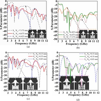
Figure 5 presents the parametric investigation executed with the position of the HFNL on the S-parameters of the diversity antenna. The analysis suggests that the upward positioning of the HFNL (from N L1 = 6.425 to 7.175 mm), diminishes the impedance matching of the antenna (Fig. 5(a)) as well as reduces the level of isolation (|S 12|>15 dB) at the lower edges of the UWB spectrum (from 3.15 to 4.6 GHz) as shown in Fig. 5(b). Moreover, an increase in width of the HFNL from 0.15 to 0.85 mm leads to a reduction in the sharpness of the band notch centered at 3.3 GHz as indicated in Fig. 5(c). With the extension in the width of the HFNL from 0.15 to 0.85 mm, the isolation provided by the HFNL is found to increase significantly along the loftier verge of the UWB spectrum and vise versa depicted using Fig. 5(d). So, in agreement with [Reference Wang and Du16], the thickness and position of the HFNL are found to influence both the impedance matching and isolation levels of the diversity antenna significantly. Figure 6 presents the current dispersal of the suggested UWB MIMO antenna, to explain the significance of each isolation improvement structure as well as the band rejection element with port 1 exclusively excited and port 2 terminated by the matched load.
Variation of (a) S 11 characteristics with the position of the HFNL, (b) S 12 with the position of the HFNL. (c) S 11 characteristics with the width of the HFNL, (d) S 12 characteristics with the width of HFNL.

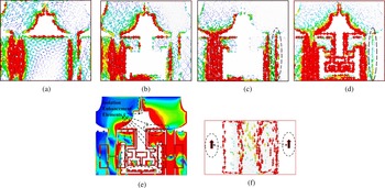
Simulated surface current dispersal over the antenna at (a) 3.1 GHz (without isolation improvement structures). (b) 5.75 GHz (with engraved modified rectangular defect in the common ground plane). (c) 3.1 GHz (without the introduction of HFNL). (d) 3.1 GHz (with HFNL). (e) 9.5 GHz (bottom view, depicting the incorporation of Koch fractal boundaries and complementary Koch fractal boundary). (f) 4.5 GHz (bottom view depicting the cross linked C-shaped resonators).

Figure 6(a) depicts the pairing of currents among PME1 and PME2 through the shared ground plane and urges the incorporation of isolation improvement structures. As shown in Fig. 6(b), to reduce the mid-band (between 4–7 GHz) coupling of the MIMO system, a modified rectangular DGS is etched in the common ground structure of the radiator. Figure 6(b) depicts the elongation of the effective electrical path stretch of currents due to the introduction of the DGS, thereby enhancing isolation in the mid bands of the UWB spectrum (see Fig. 2(b)). Figures 6(c) and 6(d) present the vector current distribution of the antenna at 3.1 GHz without and with the incorporation of the HFNL respectively. Figure 6(c) presents the strong concentration of currents near the feeding line of port 2 in the absence of the HFNL (as indicated by dotted lines). The 2nd order HFNL allows multiple new current paths with elongated lengths. As, an impact, the new coupling currents compensate for the original coupling originated as a result of sharing the ground structure and near-field coupling, thereby reducing mutual coupling [Reference Wang and Du15].
The attained result is found to justify the response presented in Fig. 3(c) (and Fig. 4(b)). Figure 6(e) outlines the introduction of Koch fractal boundaries and complementary Koch fractal boundaries (over the T-region of the DGS) in elongating the effective path length traveled by the current on the ground planes as well as the HFNL, thereby improving isolation near 7 GHz (magnitude of currents is indicated). The parallel parasitic elements (near the top) exploit field cancellation to synthetically produce an inverse field pairing route to counteract the primary pairing [Reference Mak, Rowell and Murch21] thereby enhancing isolation near 9 GHz. To achieve high isolation between 9–11 GHz, two rectangular strips are placed behind the L-shaped structure of the HFNL. The direction of currents in the rectangular strips is contrary to the direction of currents on the shared ground structure thereby strengthening isolation near 10.6 GHz. The combined effects of the Koch fractal boundaries, complementary Koch fractal boundaries, the parallel parasitic strips behind the antenna, and the rectangular strips placed behind the point of connection of the HFNL; all together improve the isolation of the diversity antenna between 6.5–11 GHz. The magnetic paring among the CPW and the cross-linked C-shaped resonators stimulates the resonators, thereby leading to a stop band in the transmission attributes of the CPW [Reference Horestani, Shaterian, Naqui, Martín and Fumeaux28, Reference Horestani, Fumeaux, Al-Sarawi and Abbott29]. The currents flows in the alike direction across the surface of the two cross-linked C-shaped resonators. Consequently, fields attached to the CPW feeding are adequate to unsettle the linked fractal resonators at their elementary resonant frequency [Reference Martin, Falcone, Bonache, Marques and Sorolla30]. The resonance frequency of cross-linked C-shaped resonators is inherently one by two when compared to the resonant frequency of a pair of non-linked resonators. In short, the cross-connected resonators render an extensive extent of shrinking in analogy to a pair of detached C-shaped resonators [Reference Horestani, Durán-Sindreu, Naqui, Fumeaux and Martín31]. A sharp and confined rejection band is acquired at 4.5 GHz (INSAT band) because of the existence of extensive inductive coupling among the CPW line and the cross-linked C-shaped resonators [Reference Martin, Falcone, Bonache, Marques and Sorolla30].
Results and discussion
Impedance aspects and radiation performance
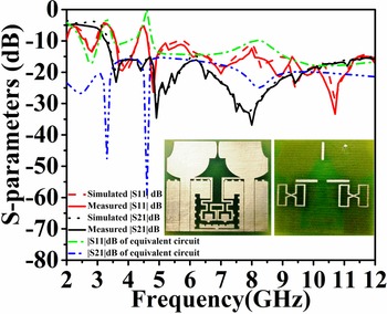
The realized model of the proposed radiator is shown in the enclosure of Fig. 7. The resonance characteristics of the prototype are validated by using Rhode and Schwarz ZVA 40 vector network analyzer (VNA). During measurements of the S-parameters, a single port of the radiator is joined to the VNA, and the alternate port is terminated employing a 50-Ω load. Figure 7 conveys that the measured operative bandwidth spans between 2.64 and 12 GHz (S 11 ≤ −10 dB) acutely eliminating two reserved limited bands at 3.3 GHz (Wi-Max), and 4.5 GHz (INSAT). Figure 7 additionally presents the analogy of the simulated and measured S 11 and S 21 characteristics. It can be inferred that the │S 21│ is beneath −15 dB for the complete UWB band (3.35–12 GHz) showing high and wideband isolation. However, some variance between the numerical and empirical findings is noticed because of the variability of the dielectric constant and the loss tangent of the substrate. The losses are also due to soldering, losses due to SMA connectors, and fabrication tolerances.
Simulated, measured, and equivalent circuit response for the S-parameters of the proposed UWB MIMO antenna (Enclosure: realized antenna prototype).

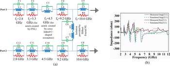
Figure 8(a) illustrates the equivalent circuit setup drawn out for the suggested UWB diversity antenna. The resonance characteristics (S 11) of the suggested diversity antenna unfold the presence of three noticeable resonances occurring at 2.8, 9.2 and 10.6 GHz. The parallel resonant circuit at 2.8 GHz is modeled by employing L 1, C 1, and R 1. The second resonance frequency is specified by implementing L 4, C 4, and R 3 in the form of a parallel resonant circuit. Likewise, the third resonant frequency (at 10.6 GHz) is configured by utilizing L 5, C 5, and R 4. It is evident from Fig. 8(b), that an excessive reactance is extended at 3.3 and 4.5 GHz by the radiator. This observation suggests that the band rejection trait at 3.3 GHz (due to the HFNL) can be configured by utilizing a parallel resonant circuit comprising L 2, C 2, and R 2. The rejection attributes at 4.5 GHz are attained due to the presence of the cross-linked C-shaped resonators and can be configured by a parallel resonant circuitry comprising L 3 and C 3. This configuring of the HFNL and the cross-linked C-shaped resonators for creating band rejection attributes are obeying the equivalent circuit for an electric LC resonator. The calculations of resonance frequency for the electric LC resonators are attained from [Reference Bahl32, Reference Wu, Kang, Chen and Tarng33] and are established to be 3.5 and 4.5 GHz. The desired results are attained after fine-tuning the calculated results for the resonant frequency of the electric LC resonators. As shown by Fig. 8(a), the HFNL can be configured by utilizing an inductive capacitive circuit consisting of L 6, L 7, C 6, and C 7. Equations (4) and (5) are exercised to acquire the resonant frequency and bandwidth of the parallel resonant circuit which are explicitly provided in [Reference Gorai, Dasgupta and Ghatak34, Reference Zhu, Gao, Ho, Abd-Alhameed, See, Brown, Li, Wei and Xu35]. The initial values of Ri, Li, and Ci (i = 1, 2, 3, 4, 5) are secured and fine-tuned by utilizing the Ansoft HF suite [36].


Equivalent circuit model and the variation of input impedance for the suggested UWB diversity antenna. (a) Equivalent circuit model. (b) Variation of input impedance and reactance. C 1 = C 12 = 4 pF, C 2 = C 11 = 14 pF, C 3 = C 10 = 15 pF, C 4 = C 9 = 4.4 pF, C 5 = C 8 = 0.13 pF, C 6 = 0.08 pF, C 7 = 0.08 pF, L 1 = L 12 = 1 nH, L 2 = L 11 = 0.166 nH, L 3 = L 10 = 0.08 nH, L 4 = L 9 = 0.085 nH, L 5 = L 8 = 1.6 nH, L 6 = L 7 = 0.085 nH, R 1 = R 3 = R 4 = R 5 = R 6 = R 8 = 50 Ω, R 2 = R 7 = 350 Ω.

The simulation and empirical outcomes presented in Fig. 8 depict high similarities.
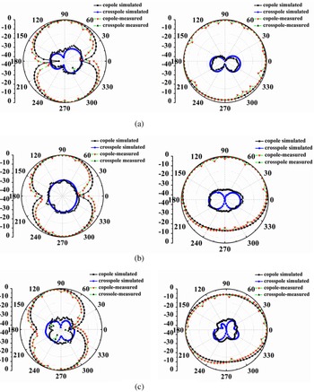
The normalized numerical and empirical 2-D radiation patterns of the MIMO antenna are given out in Fig. 9. The radiation pattern for each radiator is examined along two planes i.e. X–Z plane and X–Y plane at 3.1, 5 and 7 GHz. In the course of experimental evaluations, port 1 is singularly stimulated, whereas the alternate port is terminated employing a 50 Ω load. Figures 9(a)–9(c) indicate that the H-plane (X–Y plane) patterns across the smaller limits of the UWB range (near 3 GHz) are barely directional when analogized to the patterns at the towering limits of the UWB spectrum, which are close to omnidirectional accompanying multiple lobes as a result of higher-order resonant modes. Patterns resembling the shape of a Dumbell are noticed in the E-plane (X–Z plane). In the H-Plane (X–Y plane) the radiation patterns are moving closer to omnidirectional, signifying the attainment of a vast as well as stable reach for the UWB system applications. Next, The numerical and empirical peak gain and radiation efficiency of the suggested radiator are outlined in Fig. 10. The empirical gain is found to fluctuate between 1.04–4.82 dBi, excluding a pair of elimination bands focused at 3.3 and 4.5 GHz. The measured radiation efficiency spans between 52.60 and 89.53%. Figure 10 also depicts a deep drop in both realized gain and efficiency at 3.3 and 4.5 GHz, providing firm evidence of effective interference suppression at Wi-Max and INSAT frequencies. As a result of the symmetrical setup of the monopoles, it is deduced that exciting port 2 will produce the replica of the patterns acquired on exciting port 1.
Radiation patterns of the suggested UWB MIMO antenna (The orientation of the radiator is in y–z plane). (a) 3.1 GHz, (b) 5 GHz, and (c) 7 GHz.

Simulated and measured realized gain as well as radiation efficiency of the suggested antenna.

Diversity performance and multiplexing efficiency
To demonstrate the diversity characteristic of the intended diversity formation the envelope correlation coefficient (ECC) is computed utilizing (6) as well as (7) [Reference Tian, Lau and Ying37]. It is suggested by [Reference Sharawi38], that the major reason for the discrepancies between the ECC calculations provided in (6) and (7) is that (6) exclusively considers the isolation among the input ports of the antennas via the antennas structure, and by-no-means consider for radiated field pairing, while (7) takes into account both coupling from antennas ports as well as coupling due to the radiated fields.


For improving the reliability of detection, identical samples of individual information are sent or received through multiple antenna elements [Reference Jensen and Wallace3]. To fulfill this criterion of diversity systems, the diversity gain (DG) is computed. The DG is calculated using (8) and individually these outcomes are sketched in Fig. 11. The ECC value in Fig. 11 is conceived to be far beneath the empirical verge of 0.5 [Reference Tian, Lau and Ying37, Reference Khattak, Khan, Anab, Ullah, Al-Hasan and Nebhen39] and the DG is found to be well above 8.73 dB, depicting desirable diversity characteristics. For enlarging the spectral effectiveness of MIMO systems, spatial multiplexing is crucial [Reference Tian, Lau and Ying37]. A metric to evaluate the MIMO antenna performance in the form of spatial multiplexing is the multiplexing efficiency. A closed-form expression of multiplexing efficiency is reported in [Reference Tian, Lau and Ying37] and is given by (9).

Measured ECC and DG of the recommended antenna.

Here, the complex correlation coefficient among the two radiating monopoles is represented by ρ C, ECC ≈ |ρ C|2, as well as ƞn is the overall efficiency of the nth antenna element. Figure 12 shows the multiplexing efficiency of the intended radiator. Figure 10, as well as Fig. 12, reports the attainment of relatively identical plots for the total efficiency and the multiplexing efficiency in the intended UWB bandwidth as a result of low ECC.
Multiplexing efficiency of the proposed antenna.

Mean effective gain (MEG)
To investigate the environmental influence on the radiation properties of the radiator and to compute the comparative average power among the signals provided by each radiator MEG is utilized [Reference Kaur, Shankar Singh and Upadhyay40]. The diversity fulfillment and channel attributes of the radiator will be high if the ratio of MEG (|MEG1/MEG2|) of the pair of radiating elements is below ±3 dB [Reference Alayón Glazunov, Molisch and Tufvesson41]. Figure 13 particularly shows the stability of MEG is fairly beneath the empirical mark of ±3 dB across the entire UWB spectrum.
Measured mean effective gain (MEG) of the intended antenna.

Total active reflection coefficient (TARC)
To satisfactorily specify the efficiency and bandwidth of an existent diversity system, the S-parameter alone is insufficient. For an effective assessment of the MIMO antenna system, the TARC is utilized. The TARC also aids in investigating the outcome of phase variations among the pair of ports on the resonance response of the antenna. TARC of the two-port MIMO system [Reference Alayón Glazunov, Molisch and Tufvesson41] can be decided by applying (10).

The TARC for the diversity system needs to be restricted to <0 dB [Reference Chae, Oh and Park42, Reference Gautam, Saini, Agrawal and Rizvi43]. The recommended antenna manifests a TARC below −1.53 dB for the entire operating band as conveyed by Fig. 14.
TARC for the suggested radiator.

Time domain response of the UWB MIMO antenna
Figure 15 shows that the group delay for the recommended radiator lies within 1 ns which shows that the intended radiator is distortionless. Moreover, it is detected that the pulse-preserving ability is the finest when the transmit and receive radiating systems are facing each other (aligned along the x-axis), with a correlation factor of 0.913.
Group delay variations of the intended radiator (inset: Obtained signal in face-face orientation).

An analogy among the recommended antenna as well as the formerly communicated UWB MIMO radiators in [Reference Su, Lee and Chang13–Reference Zhang and Pedersen19] is enumerated in Table 1. The tabular analogy depicts the newness of the recommended antenna over the UWB MIMO radiators published in the recent past.
Comparison of the recommended UWB MIMO antenna with previously reported antennas

Conclusion
The paper describes and investigates, a closely-packed dual band-notched CPW-fed UWB MIMO antenna with high isolation. The amalgamation of the HFNL DGS with Koch fractal boundary, and parasitic strips results in mutual coupling beneath −15 dB even with a minimal inter-element spacing of 0.51 mm. The recommended antenna possesses a wide operational bandwidth spanning between 2.64 and −12 GHz with a peak realized gain of 4.82 dB. The band notch characteristics at 4.5 GHz are obtained by two cross-linked C-shaped parasitic resonators while standing wave creation as a result of an impedance mismatch due to the introduction of HFNL allows the rejection of the Wi-Max band (3.3−3.7 GHz). This eliminates the need for an extra resonator for creating a band notch. The proposed CPW-fed design has the inherent advantage of being integrated into portable UWB devices and is compatible with MIC/MMIC designs due to the possession of an 80% clearance area behind the antenna. The simulated |S 11| dB and |S 12| dB comply with the empirical outcomes as well as those acquired from an equivalent circuit model of the recommended MIMO antenna. Satisfactory radiation and diversity characteristics of the recommended MIMO radiator are attained for portable wireless UWB MIMO applications.
Conflict of interest
The authors declare that they have no known conflict of interests or personal relationships that could have appeared to influence the work reported in this paper.
 Jeet Banerjee is currently teaching as an Assistant Professor in the Dept. of Electrical and Electronics Engineering, at Adamas University, Kolkata, West Bengal, India. Mr. Banerjee is parallel-associated with the Dept. of ECE, NIT Durgapur (India) as a Part-Time Research Scholar and is in the advanced stage of his Ph.D. studies. His primary research area lies in Fractal UWB MIMO antenna design.
 Abhik Gorai received his M.Tech and Ph.D. in the year of 2013 and 2020 respectively from National Institute of Technology, Durgapur. He served in Huawei Telecommunication and Alcatel Lucent after his B.Tech. He now holds a position of Assistant Professor in Kalinga Institute of Industrial Technology. His primary research interests are in Fractal UWB antenna, metasurface, metamaterials and substrate integrated waveguide based antenna and filter design.
 Rowdra Ghatak initiated his career in microwave engineering as a trainee with the CEERI Pilani, Pilani, India, in the domain of fabrication and testing of S-band magnetrons. Thereafter, he served at the National Institute of Science and Technology, Berhampur, and The University of Burdwan. He is currently a Professor with the Electronics and Communication Engineering Department, National Institute of Technology Durgapur, Durgapur, India. He has more than 250 publications in various national/international journals and conferences. His research interests include in the areas of fractal antenna, metamaterials, application of evolutionary algorithms to electromagnetic optimization problems, RFID, and computational electromagnetic and microwave passive and active circuit design. Dr. Ghatak was a recipient of the URSI Young Scientist Award in 2005. He also received support under the DST Young Scientist scheme for the development of UWB radiating systems for imaging RADAR. He has served in various selection as well as project review committees in the State as well as in the National domain. He has also served as a reviewer for a NPTEL course on antennas. He is a member of the board of studies at UG and PG level at various state and central Universities. He is also serving as a Research Advisor to the TCS Research in the domain of mmWave radio design and radiating systems and his current research interests include linear and non-linear CAD techniques and low noise receivers.