Introduction
With the rapid development of modern wireless communication, the integration of various components into one module to realize size reduction and multifunctionality has gained a lot of attention. A filtering antenna combines an antenna and a filter, removing the interconnection and matching circuits to reduce the size and insertion loss.
Patch filtering antennas have been extensively studied to achieve filtering characteristics by combining patch antennas with parasitic patches [Reference Cheng, Zhou, Yang, Wu and Huang1], shorting pins [Reference Yang, Xun, Che, Feng, Zhang and Xue2], defected ground structures [Reference Yang, Chen, Xue, Che, Shen and Feng3], and coupled microstrip lines [Reference Zhang, Liu, Feng, Zhang and Wong4]. However, patch filtering antennas typically exhibit a low Q-factor and high radiation loss. Substrate integrated waveguide (SIW) not only inherits the characteristics of cavity structure with low loss and high Q-factor but also retains the advantages of microstrip antenna with low profile, lightweight, and convenient to be integrated, so that the integration of antenna and filter on SIW has been put forward [Reference Liu, Zhu, Choi and Zhang5–Reference Chaturvedi, Kumar, Althuwayb and Ahmadfard12].
Frequency selectivity is important in the design of SIW filtering antennas, which is related to radiation nulls. There are a variety of ways to attain radiation nulls, including shorting vias [Reference Hu, Tang, Li, Wang and Li13, Reference Liu14], novel feeding structures [Reference Brown and Saavedra15], parasitic patches [Reference Hu, Guo, Pan, Yan, Tang and Wang16, Reference Yan, Pan, Guo, Hu, Bi, Wang and Xie17], and etching slots [Reference Li, Pang, Feng, Wang and Lei18, Reference Liu, Zhang, Xu and Shi19]. Nevertheless, wide bandwidth is a difficulty in the design of SIW filtering antennas. Two typical methods to broaden the impedance bandwidth are increasing the cavity height and combining multiple modes. For instance, a dual-layer SIW filtering antenna with a rectangular patch with metal vias and parasitic patches is proposed in [Reference Yang, Pan, Shi and Zhang20]. Both the vias-loaded patch and the parasitic patch generate two additional resonant modes, increasing the filter bandwidth and realizing a radiation null in the upper sideband. In [Reference Liu, Zhu, Wang and Wu21], a hybrid structure filtering antenna with an SIW cavity and circular patch is proposed. The patch is used to excite an additional TM110 mode, which is combined with the TE110 and TE120 modes excited by the SIW cavity to increase both the bandwidth and the out-of-band suppression. Based on this principle, a hybrid structure filtering antenna with a triangular patch further introduces cross-coupling of the SIW cavity and a U-shaped slot to achieve two controllable radiation nulls in [Reference Li and Deng22].
In this letter, a low-profile slot antenna with good filtering response is proposed. The antenna has a simple structure without additional filtering circuits. Multiple high-order modes are excited by the zigzag SIW cavities to increase the potential bandwidth. A bow-tie shaped radiating slot is etched on the surface of the last stage resonant cavity, and the impedance matching is optimized by combining the small rectangular slots on the surface of the first and last stage resonant cavities. The slots merge four operating modes into a single band and reduce the modes impedance to increase the bandwidth of the proposed antenna. Moreover, three radiation nulls in the stopband improve the out-of-band rejection and enhance the frequency selectivity.
Antenna design
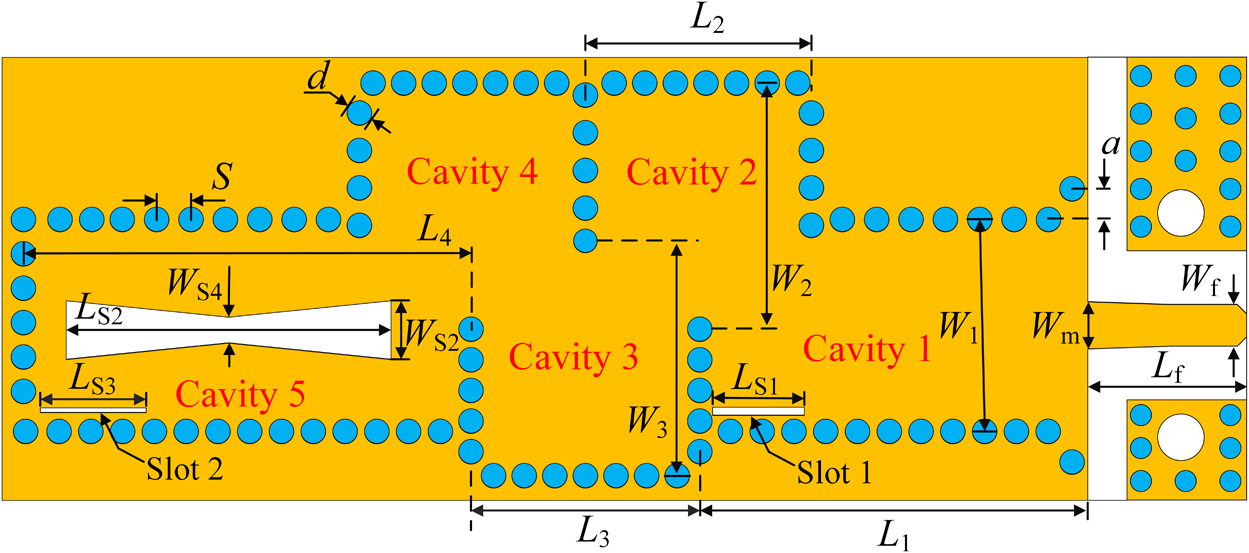
Figure 1 shows the structure of the proposed wideband filtering antenna, which is designed on a single-layer Rogers RO4003 substrate with a thickness of h = 0.813 mm ( $\epsilon_{\text{r}} = 3.55$, tanδ = 0.0027). It consists of a bow-tie shaped slot and two rectangular slots etched on the top surface of the zigzag SIW cavities. A microstrip-to-SIW transition is used to achieve the 50 Ω impedance conversion. The diameter of the copper column is d = 1.05 mm. In order to avoid energy leakage during energy transmission, the distance between two copper columns should not be too large, and the conditions to be satisfied are
 $d/S \gt 0.5$ and
 $d/\lambda_0 \lt 0.1$. λ 0 is the wavelength of the operating frequency in free space.
Configuration of the proposed antenna. Here,  $W_{\text{1}} = 7.95$,
 $L_{\text{1}} = 15.95$,
 $W_{\text{2}} = 9.4$,
 $L_{\text{2}} = 8.55$,
 $W_{\text{3}} = 8.94$,
 $L_{\text{3}} = 8.67$,
 $L_{\text{4}} = 17.96$,
 $W_{\text{f}} = 1.77$,
 $L_{\text{f}} = 6.75$,
 $W_{\text{m}} = 2.0$,
 $L_{\text{S1}} = 3.9$,
 $L_{\text{S2}} = 13.8$,
 $L_{\text{S3}} = 4.5$,
 $W_{\text{S2}} = 2.50$,
 $W_{\text{S4}} = 1.1$, S = 1.46, a = 1.3, d = 1.05 (unit: mm).

Compared to conventional rectangular SIW cavities, zigzag SIW cavities make it easier to introduce cross-coupling between nonadjacent cavities to control the transmission zeros, which are more suitable for enhancing filter bandwidth [Reference Augustine and Vinoy23]. Therefore, the proposed filtering antenna adopts a five-cavity zigzag structure to achieve a wideband filtering effect.
According to the fundamental theory of rectangular waveguides, the resonant frequency of the TEmn0 mode in a rectangular SIW can be described as [Reference Tang, Tong and Chen24]:
 \begin{equation}
f_{\text{mn0}} = \frac {c_{\text{0}}} {2\sqrt{\epsilon_{\text{r}}}}
\sqrt{\left(\frac{m}{W_{\text{eff}}}\right)^2+\left(\frac{n}{L_{\text{eff}}}\right)^2}
\end{equation}
 \begin{equation}
W_{\text{eff}} = W - \frac{d^2}{0.95S}
\end{equation}
 \begin{equation}
L_{\text{eff}} = L - \frac{d^2}{0.95S}
\end{equation}
where  $c_{\text{0}}$ is the speed of light in vacuum, m and n represent the wave modes operating in the SIW resonant cavity, as well as W eff and L eff are the effective width and length of the rectangular SIW resonant cavity.
The frequency of the proposed antenna’s fundamental mode TE110 can be initially determined by formulas (1)–(3). The calculated frequency of the TE110 mode is 10.28 GHz, which is close to 10.43 GHz from the simulation. The cavities are bounded by decoupling walls. The length and width of the cavities can be adjusted to control the resonant frequency for a good bandwidth. The impact of the metal wall position and slot antenna on the higher order modes should be taken into consideration during the design process.
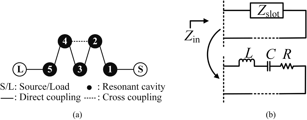
The coupling topology of the zigzag SIW cavities is shown in Fig. 2(a). There is a cross-coupling between cavity 2 and cavity 4, while the other neighboring cavities are directly coupled to each other. Cross-coupling is a nonadjacent connection energy path formed by nonadjacent resonators, and its coupling phase and amplitude can introduce transmission nulls. Cavities 2 and 4 are not connected directly but indirectly through cavity 3, forming a negative polarity cross-coupling that results in the first transmission null of the lower stopband. Therefore, the cross-coupling strength between cavities 2 and 4 is affected by the length and width of cavity 3. The half-wavelength bow-tie radiation slot is etched on the surface of the final stage resonator, working as the equivalent load of the filtering antenna. To preserve the filtering effect, it is essential to maintain a constant external coupling coefficient Q EXT for the last stage resonator of the filtering antenna during the design of the slot antenna. In this case, it can be considered that the equivalent circuit model of the bow-tie radiation slot is consistent with the resonator, both of which are resonant circuits composed of series RLC, as shown in Fig. 2(b). The bandwidth of the radiation slot should be larger than the filtering bandwidth.
(a) Coupling schematic topology of the zigzag SIW cavities (b) and the equivalent circuit of the radiation slot in the last stage resonator.

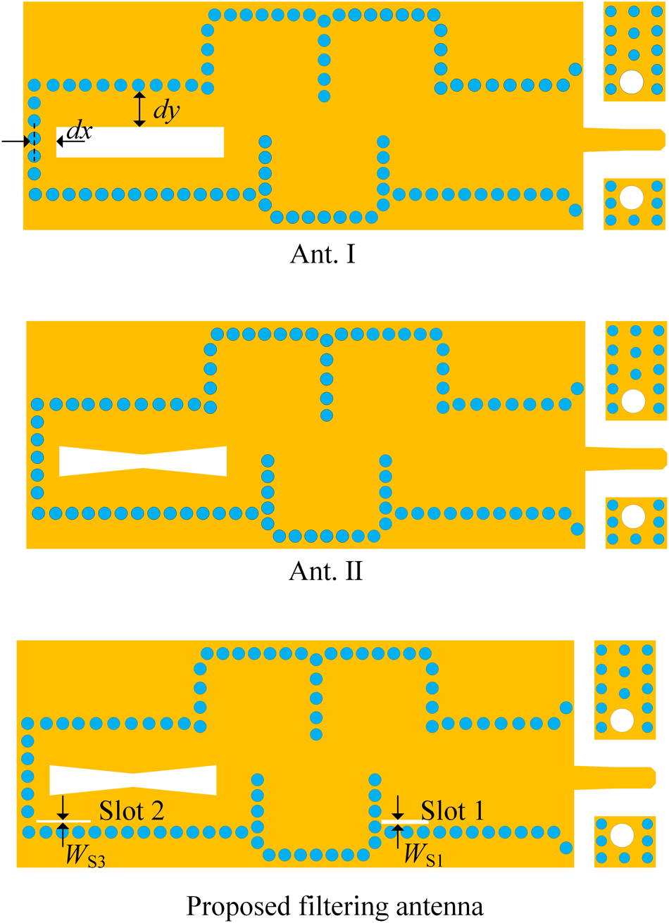
Figure 3 shows the evolution process of the proposed filtering antenna. At first, a rectangular slot is etched on the surface of the last stage of the resonant cavity in Ant. I. The Q EXT between the radiation slot and the zigzag SIW cavities is controlled by  $L_{\text{S3}}$, dx, and dy. When
 $L_{\text{S3}} = 4.5\,\mathrm{mm}$,
 $dx = 0.93\,\mathrm{mm}$, and
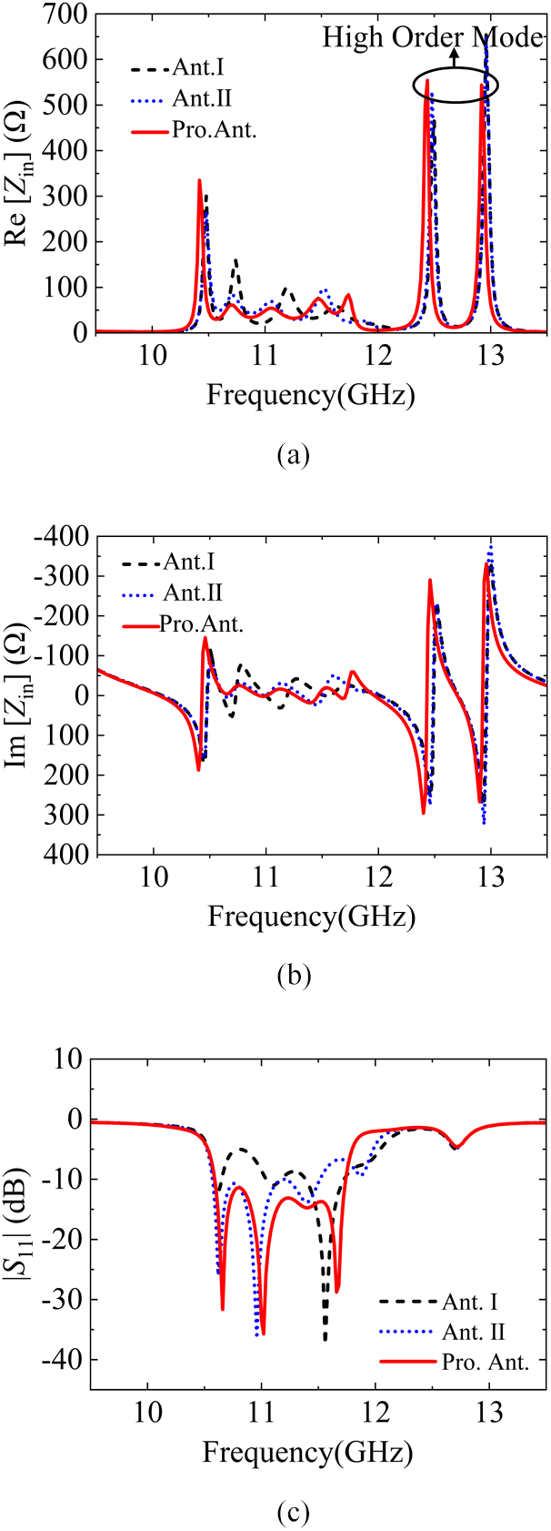
 $dy = 3.45\,\mathrm{mm}$, the filtering antenna has a relatively good filtering effect. As the input impedances shown in Figs. 4(a) and (b), it can be seen that Ant. I has four resonant frequencies in the frequency band, but its impedance matching is narrow, and the radiation properties in the passband are poor. A bow-tie slot is used as a substitute for the rectangular slot in Ant. II for wideband impedance matching. By comparison, it is found that the bow-tie radiation slot reduces the input impedance of each mode and merges them into a single band, which preliminarily realizes the effect of broadband impedance matching.
Evolution process of the proposed antenna with dx =0.93, dy = 3.45,  $W_{\text{S1}} = 0.35$, and
 $W_{\text{S3}} = 0.2$ (unit: mm).

(a) Real part and (b) imaginary part of the input impedance, as well as (c) the reflection coefficients of Ant. I, Ant. II, and the proposed antenna.

To further improve the impedance matching and make the gain curve flatter within the passband, two small rectangular slots 1 and 2 are etched in the first cavity and the last cavity of the proposed filtering antenna. The widths of the slots 1 and 2 are 0.35 mm and 0.2 mm, respectively, which are related to the impedance matching and the edge selectivity to a certain extent. The sub-wavelength rectangular slots control the distribution of surface current, introducing equivalent inductive and capacitive components. From Figs. 4(b) and (c), it can be seen that these not only improve the impedance within the operating frequency band but also improve the coupling performance between cavities, optimizing the edge selectivity of the antenna passband. In order to diminish the effect on the resonant frequency, the impedance-matched slots should be loaded with zero electric field, so slots 1 and 2 are set at the edges of the cavities where the electric field is weak.
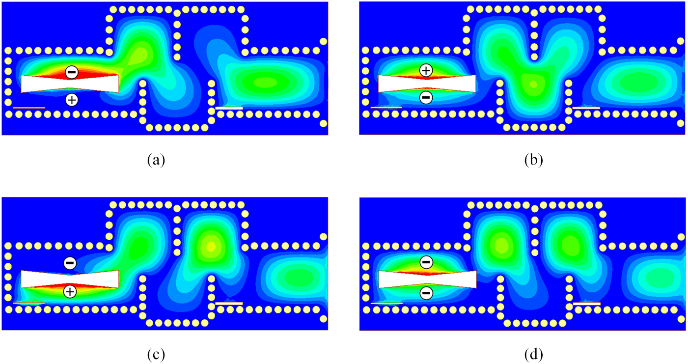
The energy passes through the zigzag SIW cavities and then is radiated into free space by the formation of transverse electric fields on both sides of the bow-tie slot. Figure 5 shows the electric field of the proposed antenna at the resonance frequency to facilitate analysis. In Figs. 5(a)–(c), the bow-tie slot disturbs the original electric field pattern in the cavities, creating an abrupt voltage change in the electric field on both sides of the slot, which is equivalent to an impedance in series on the transmission line. The magnitude and phase of the surface currents are different on opposite sides of the bow-tie slot, which helps it to radiate and broaden bandwidth. The electric field pattern at 11.66 GHz in Fig. 5(d) shows that both sides of the slot have the negative voltage. The phase and amplitude of the voltage are different, so the above theory still works.
Simulated electric field distributions of the proposed wideband filtering antenna at resonant frequencies: (a) 10.66, (b) 11.00, (c) 11.40, and (d)11.66 GHz.

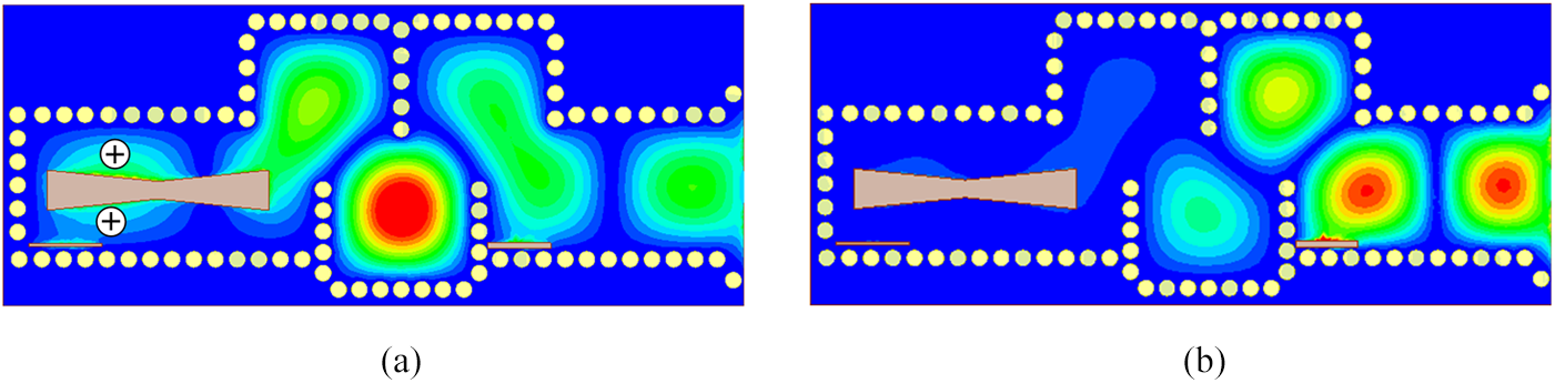
Apart from the radiation null introduced at the lower stopband edge by the cross-coupling between cavities 2 and 4, the radiation slot also introduces new cross-coupling paths, resulting in two radiation nulls in the upper stopband. Figure 6 demonstrates the electric field at the two radiation nulls in the upper stop band of the proposed antenna. The electric field on both sides of the slot at 12.58 GHz is in-phase and the mode is a nonresonant mode that lies outside the passband, which results in a radiation null. The radiation null at 13.38 GHz is due to the fact that the zigzag SIW cavities confine the energy in cavities 1, 2, and 3, and very little energy reaches the periphery of the slot.
Simulated electric field distributions at radiation nulls: (a) 12.58 and (b) 13.38 GHz.

Simulated and measured results
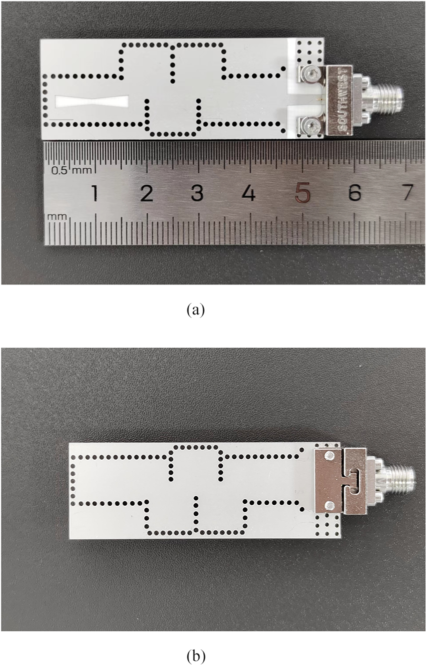
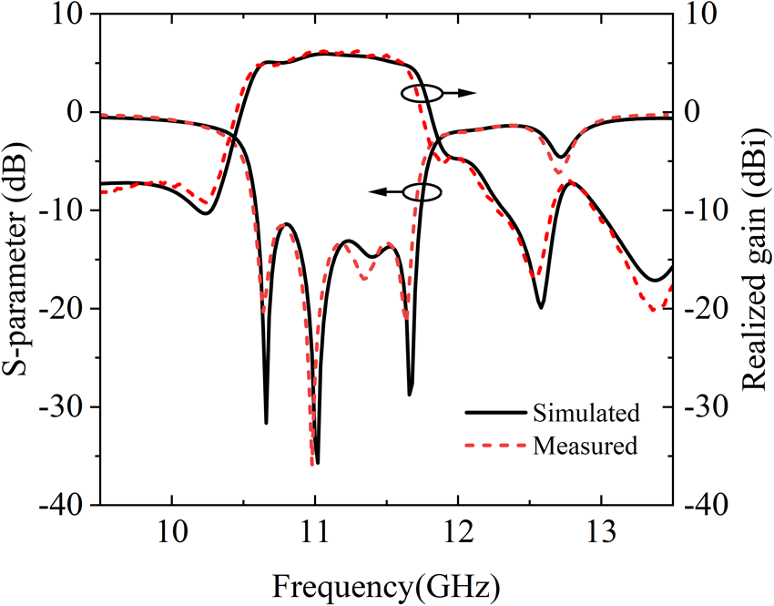
The proposed wideband filtering antenna has been fabricated, and the photograph is shown in Fig. 7. An SMA connector is connected to the microstrip-to-SIW transition of the proposed antenna. The realized gain and radiation patterns of the developed filtering antenna are measured by the N5227B PNA Microwave Network Analyzer, which is obtained by comparing with a standard horn antenna in an anechoic chamber. Figure 8 depicts the simulated and measured results of the proposed antenna. It can be seen that the measured −10 dB bandwidth is 10.1%, and a good filtering response and frequency selectivity are obtained in the range of 10.58–11.7 GHz. At the passband edge, the loss coefficient increases rapidly to nearly 0 dB, showing good filtering characteristics. The measured peak gain is 6.19 dBi, which is close to the simulated value of 6.25 dBi. The measured realized gain curve shows three radiation nulls at 10.24, 12.54, and 13.36 GHz, respectively. These gain nulls within the stop band enhance out-of-band rejection. The simulated and measured radiation rejection levels are more than 20 dB and 15 dB, respectively, showing good frequency selectivity.
Prototype of the proposed wideband filtering antenna: (a) top view and (b) bottom view.

Simulated and measured results of the proposed filtering antenna.

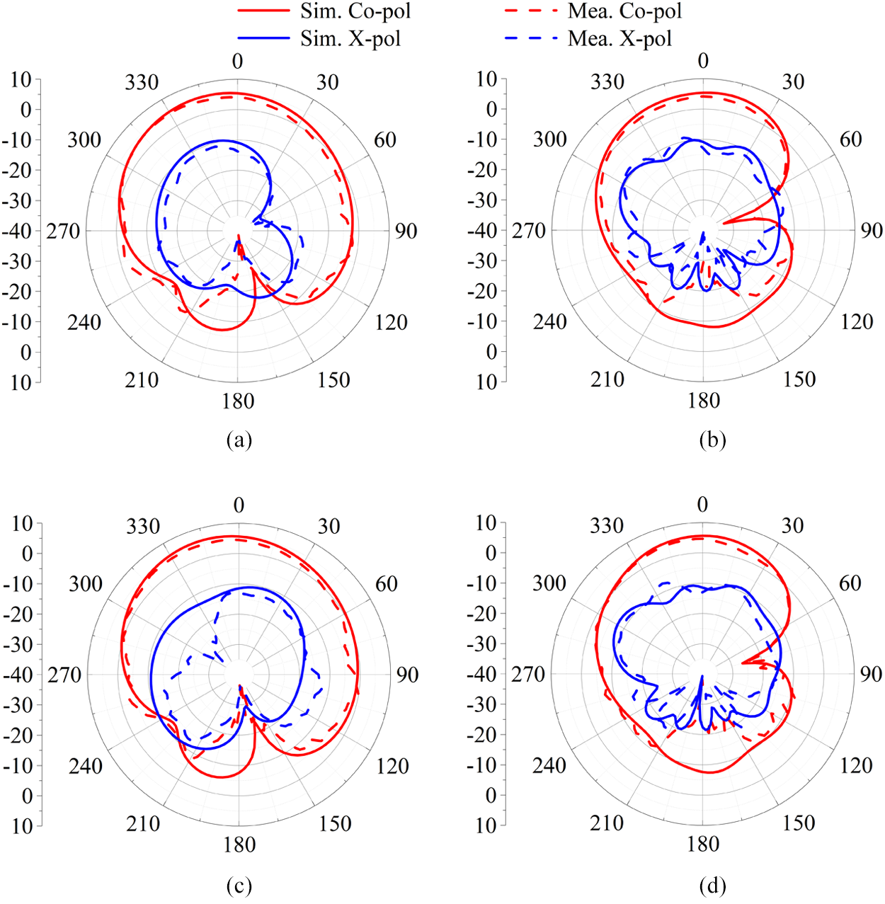
The measured radiation patterns of the prototype at 10.9 and 11.3 GHz are shown in Fig. 9. The radiation pattern of the proposed antenna remains stable in the filtering passband. The upper part of the measured radiation patterns shows reasonable agreement with the simulations, but the lower part has a few deviations, which are caused by the foam table supporting the antenna. In addition, the cross-polarization measured in the E-plane (H-plane) is less than −10 dB.
Simulated and measured radiation patterns of the proposed filtering antenna: (a) E-plane at 10.90 GHz, (b) H-plane at 10.90 GHz, (c) E-plane at 11.30 GHz, and (d) H-plane at 11.30 GHz.

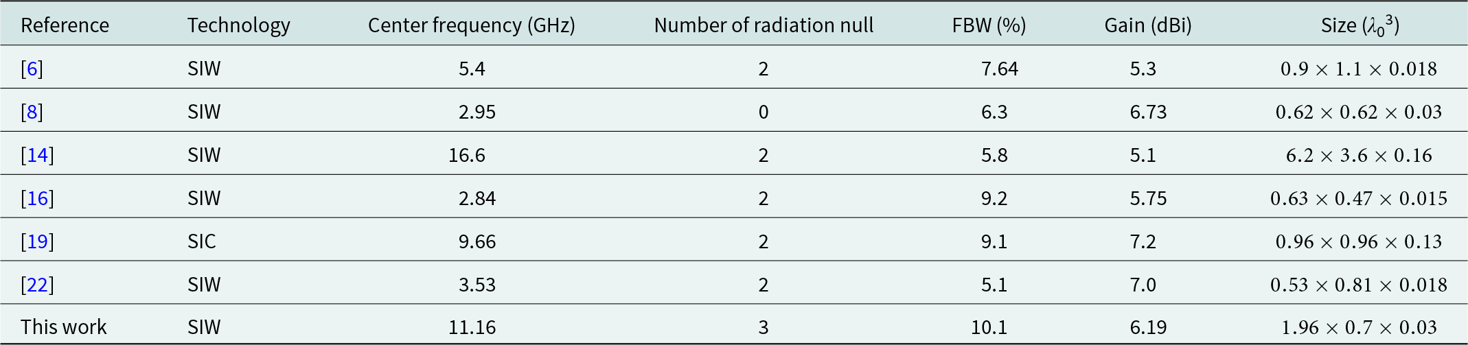
Table 1 compares the performance of the proposed antenna with other previous filtering antennas. It can be seen that the proposed filtering antenna has an obvious advantage in bandwidth performance, which is attributed to the zigzag SIW cavities and bow-tie radiation slot to merge multiple operating modes into a single band.
Comparison among the proposed work and other SIW filtering antennas

Conclusion
In this letter, a wideband zigzag SIW cavities filtering antenna is designed, analyzed, and measured. Compared with some existing SIW filtering antennas, the design can meet the requirements of low profile, high gain, and multiple radiation nulls. The zigzag SIW cavities excited multiple modes, and the slot antennas reduced the modes impedance and merged the multiple modes in the passband, which effectively improved the bandwidth of the SIW slot filtering antenna.
Acknowledgements
This work was supported in part by the National Natural Science Foundation of China under Grant 62101139, in part by the Guangdong Basic and Applied Basic Research Foundation under Grant 2023A1515012831, and in part by the State Key Laboratory of Millimeter Waves under Grant K202416.
Competing interests
The authors declare none.

Zhi-Xia Du received the B.S. degree in applied physics and Ph.D. degree in information and communication engineering from South China University of Technology, Guangzhou, China, in 2014 and 2019, respectively.
From 2017 to 2018, he was with the Applied Electromagnetics Research Group, University of California, San Diego, CA, USA, as a Visiting Graduate. From 2019 to 2020, he worked as a senior engineer in Huawei Technologies Co., Ltd, Shenzhen, China. He is currently an Assistant Professor with the School of Integrated Circuits, Guangdong University of Technology. He currently has more than 40 publications and more than 20 issued patents. His research interests include active antenna array, wireless power transfer, time-modulated metasurfaces, and microwave circuits.
Dr. Du has served as Technical Program Committee (TPC) member and Session Organizer/Chair for a number of conferences. He was awarded the Best Student Paper Prize in the 2015 National Conference on Microwave and Millimeter Wave Technology (NCMMW).

Mingqiu Huang received the B.S. degree in integrated circuit design and integrated system from Guangdong University of Technology, Guangzhou, China, in 2023, where he is currently pursuing the M.S. degree. Her research interests include filtering antennas and beam-controllable antenna arrays.

Zhenming Pan received the B.S. degree in electrical engineering and automation from Guangdong Ocean University, Zhanjiang, China in 2022. He is currently pursuing the M.S. degree with the School of Information Engineering, Guangdong University of Technology, Guangzhou. His research interests include filtering antenna and high-efficiency antenna in package design for RF/microwave and millimeter-wave applications.

Qiong-Sen Wu received the B.Eng. degree in Information Engineering and the M.Eng. degree in Electromagnetism and Microwave Engineering from South China University of Technology, Guangzhou, China, in 2011 and 2014, respectively, and the Ph.D. degree in electrical and computer engineering from the University of Macau, Macau, SAR, China, in 2018. He joined the Antenna and Electromagnetic-Wave Laboratory in University of Macau, Macau, SAR, China, as a research fellow in May 2018. He is currently an associate professor with the School of Integrated Circuits, Guangdong University of Technology. His current research interests include microwave circuits and planar antennas with improved functionalities.