I. INTRODUCTION
Nanocolloidal crystals (NCCs) have been intensively studied due to their promising applications, such as optical devices, Reference Holtz and Asher1 data storage, Reference Vlasov, Bo, Sturm and Norris2,Reference Sun, Murray, Weller, Folks and Moser3 waveguides, Reference Rinne, Garcia-Santamaria and Braun4–Reference Istrate and Sargent6 and sensors. Reference Lee and Asher7 However, their poor mechanical properties significantly hinder these applications. Reference Zhang, Prosser, Feng and Lee8–Reference Shen, Yang, Lu, Bao and You12 Thermal sintering is the most common reinforcement technique for colloid assemblies. Reference Miguez, Blanco, Lopez, Meseguer, Yates, Pemble, Lopez-Tejeira, Garcia-Vidal and Sanchez-Dehesa13–Reference Machii and Nakamura20 Moreover, to synthesize inverse opals which are another type of emerging advanced optical materials, it is typical to use NCCs as infiltration templates which are usually pre-reinforced to maintain their integrity during the template-infiltration process, Reference Zhou, Li, Ye, Liu, Wang, Zhao, Jiang and Song11,Reference Zakhidov, Baughman, Iqbal, Cui, Khayrullin, Dantas, Marti and Ralchenko21–Reference Blanco, Chomski, Grabtchak, Ibisate, John, Leonard, Lopez, Meseguer, Miguez, Mondia, Ozin, Toader and van Driel32 for example, SiO2 NCC templates are commonly sintered at temperatures above 800 °C, Reference Zakhidov, Baughman, Iqbal, Cui, Khayrullin, Dantas, Marti and Ralchenko21–Reference Johnson, McComb, Richel, Treble and De La Rue26,Reference Gu, Kubo, Fujishima and Sato28,Reference King, Gaillot, Graugnard and Summers30–Reference Blanco, Chomski, Grabtchak, Ibisate, John, Leonard, Lopez, Meseguer, Miguez, Mondia, Ozin, Toader and van Driel32 and polystyrene NCC templates are commonly sintered at 80–85 °C. Reference Zhou, Li, Ye, Liu, Wang, Zhao, Jiang and Song11,Reference Kubo, Gu, Takahashi, Fujishima, Segawa and Sato29
The initial stage of sintering-induced reinforcement of colloid assemblies involves the formation of interparticle neck through various mechanisms, such as surface diffusion, volume diffusion, evaporation-condensation, and plastic/viscous flow. Reference Machii and Nakamura20,Reference Poppe33–Reference Fang37 The dynamics of neck growth depends strongly on sintering temperature T s, particle size, and the associated neck-formation mechanism(s). Reference Machii and Nakamura20,Reference Poppe33–Reference Fang37 For example, Poppe quantitatively studied the effects of sintering temperate and duration on neck growth for monodisperse SiO2 micro-colloids (MCs). Reference Poppe33 Poppe found that Reference Poppe33 the SiO2 MC assembly has a melting temperature of ∼1250 °C, and that significant sintering-induced neck formation occurs at T s ≳ 1000 °C. Also, the dominant mechanism of neck transitions from surface diffusion to viscous flow at ∼1150 °C. It was also found that the neck growth depends strongly on the sintering temperature T s but weakly on the sintering duration t s (neck radius ∝ ∼t s 1/6 at a T s). Reference Poppe33
The effects of sintering on the structure and optical properties of NCCs have also been extensively studied. Reference Mayoral, Requena, Moya, López, Cintas, Miguez, Meseguer, Vázquez, Holgado and Blanco14–Reference Míguez, Meseguer, López, Blanco, Moya, Requena, Mifsud and Fornés17,Reference Gates, Park and Xia19 Many of these studies have shown that that sintering can induce crack formation and film delamination, Reference Van Le, Ross, Velarde, Legg and Wirth16,Reference Míguez, Meseguer, López, Blanco, Moya, Requena, Mifsud and Fornés17,Reference Kuai, Badilescu, Bader, Brüning, Hu and Truong24 jeopardizing the optical properties of NCCs. Reference Van Le, Ross, Velarde, Legg and Wirth16,Reference Míguez, Meseguer, López, Blanco, Moya, Requena, Mifsud and Fornés17,Reference Kuai, Badilescu, Bader, Brüning, Hu and Truong24 Moreover, high temperature sintering may preclude the use of NCCs on polymer substrates, commonly used for flexible electronics. Despite these prior reports, surprisingly little is known about the effects of sintering on the mechanical properties of NCCs.
Material infiltration has been considered as another approach for reinforcing NCCs, Reference Zhang, Zhang, Lee, Cheng and Feng38–Reference Miguez, Tetreault, Hatton, Yang, Perovic and Ozin41 although such an approach is typically used to fabricate inverse opals from NCCs. Reference Zhou, Li, Ye, Liu, Wang, Zhao, Jiang and Song11,Reference Chen, Wang, Wen, Zhang, Wang, Song, Jiang and Zhu27–Reference Kubo, Gu, Takahashi, Fujishima, Segawa and Sato29,Reference Li, Wang, Pan, Cui, Xu, Wang, Song and Jiang42 Based on our previous studies, Reference Zhang, Zhang, Lee, Cheng and Feng38,Reference Zhang, Zhang, Lee, Cheng and Feng39 the associated reinforcement mechanism is interparticle bonding (IPB) induced by materials deposition at interparticle junctions. Reference Zhang, Zhang, Lee, Cheng and Feng38–Reference Miguez, Tetreault, Hatton, Yang, Perovic and Ozin41 The mechanism is also earlier observed by Gallego-Gómez et al., Reference Gallego-Gómez, Morales Flórez, Blanco, de la Rosa Fox and López10,Reference Gallego-Gomez, Blanco and Lopez40 and they found that, after establishing interparticle bonds in silica NCCs by replicating the interparticle capillary bridges with chemical vapor deposition (CVD)-silica, each NCC behaves as a monolithic nanoframe with much less creep compared to the as-assembled counterparts. CVD Reference Blanco, Chomski, Grabtchak, Ibisate, John, Leonard, Lopez, Meseguer, Miguez, Mondia, Ozin, Toader and van Driel32,Reference Miguez, Tetreault, Hatton, Yang, Perovic and Ozin41,Reference Wang, Wen, Ge, Sun, Zheng, Song and Jiang43–Reference Galisteo, García-Santamaría, Golmayo, Juárez, López and Palacios45 and atomic layer deposition (ALD) Reference Zhang, Prosser, Feng and Lee8,Reference Dafinone, Feng, Brugarolas, Tettey and Lee9,Reference Zhang, Zhang, Lee, Cheng and Feng38,Reference Zhang, Zhang, Lee, Cheng and Feng39,Reference Sechrist, Schwartz, Lee, McCormick, Piestun, Park and George46,Reference Moon and Yang47 have been used for infiltration-based mechanical reinforcement. Compared to conventional CVD, ALD process involves self-limiting surface reactions, enabling precise control of deposition and provides superior film conformity and uniformity. Reference George48–Reference Scharrer, Wu, Yamilov, Cao and Chang52 It should be mentioned that, Blanco et al. Reference Blanco, Gallego-Gómez and López53 and Gallego-Gómez et al. Reference Gallego-Gomez, Blanco and Lopez40,Reference Gallego-Gómez, Blanco, Canalejas-Tejero and López54 recently reported a “one-pulse CVD” process by eliminating any water cycles; thus, the precursor reacts only with water pre-adsorbed in the structure, which is also self-limiting by nature and produces precisely-controlled deposition.
In our previous studies, ALD treatment has been shown to significantly harden and stiffen disordered nanoparticle assemblies Reference Zhang, Prosser, Feng and Lee8,Reference Dafinone, Feng, Brugarolas, Tettey and Lee9 as well as NCCs. Reference Zhang, Zhang, Lee, Cheng and Feng38,Reference Zhang, Zhang, Lee, Cheng and Feng39 For example, after Al2O3 ALD treatment, the SiO2 NCCs can be drastically stiffened by a factor of 30 and hardened by a factor of 150, Reference Zhang, Zhang, Lee, Cheng and Feng39 and the unstable deformation of NCCs can be also largely suppressed. Reference Zhang, Zhang, Lee, Cheng and Feng38 It was found that, the ALD-treatment allows the precise tuning of the IPB by depositing a reinforcing layer around all of the nanocolloids (NCs) in NCCs. Reference Zhang, Zhang, Lee, Cheng and Feng39 By increasing the ALD thickness, the deformation mechanism of NCCs transitions from granular to bonded granular and, finally, to particle-reinforced composite behavior. Reference Zhang, Zhang, Lee, Cheng and Feng39
Thus, both sintering and infiltration treatments can be used to reinforce NCCs, and tuning IPB is the major reinforcing mechanism for both approaches. However, as aforementioned, little is known about the effects of sintering on the mechanical properties of NCCs. This article provides the first quantitative comparison on the reinforcement due to sintering and ALD treatments. The effects of two approaches on the fracture behavior of NCCs are also discussed in first time.
In this study, sintering and Al2O3-ALD are used to mechanically reinforce NCCs composed of monodisperse 254 and 289 nm SiO2 NCs. The reinforcement effects of these two techniques are systematically studied and compared using nanoindentation. We find that the ALD treatment is more effective in stiffening, hardening, and toughening NCCs without causing significant morphology change.
II. EXPERIMENTAL
Monodisperse 254 ± 19 and 289 ± 13 nm SiO2 NCs were synthesized using the Stöber method. Reference Stöber, Fink and Bohn55 Subsequently, NCCs (>10 μm thick) were prepared using the convective self-assembly method Reference Wang, Wan, Li, Cai, Li, Zhao and Li56–Reference Yan, Zhou and Zhao58 on Si(001) substrate at 27 °C and relative humidity of 67%. In the paper, unless otherwise specified the NCCs refer to the 254 nm NCCs. The reflectance spectra of as-assembled NCCs were characterized using a Filmetrics F40-UVX system (Filmetrics, Inc., San Diego, California) with 250 µm aperture and 10× objective.
The 254 nm NCCs were sintered at 850, 950, 1000, and 1100 °C for 1 h, respectively, and a 3 h-850 °C sintering was also conducted. For each sintering process, the temperature ramp rate was 5 °C/min, and the furnace was powered off immediately after sintering; the samples were not taken out until the furnace was naturally cooled to room temperature.
Al2O3 ALD of up to 144 cycles was performed at 150 °C using a Savannah 200 from Cambridge NanoTech, Inc. (Waltham, Massachusetts). For simplicity, throughout this paper, “#ALD” represents the number of ALD cycles; for example, “15ALD 254 nm NCC” represents a 15-cycle-Al2O3-ALD-treated NCC composed of 254 nm SiO2 NCs. Based on our previous studies on the similar systems, Reference Zhang, Zhang, Lee, Cheng and Feng38,Reference Zhang, Zhang, Lee, Cheng and Feng39 the ALD growth rate is found to be ∼0.07 nm/cycle.
The topography was characterized using a Hitachi S-4800 scanning electron microscope (SEM; Hitachi Ltd., Tokyo, Japan). The mechanical properties were characterized using a Nano Indenter™ G200 from Keysight™ Technologies, Inc. (Santa Rosa, California) with continuous stiffness measurement (CSM) capability. A diamond cube-corner tip was used with its area function being calibrated in 20–1800 nm. Prior to indentation, the indenter was stabilized with the thermal drift rate <0.05 nm/s. At least eight CSM-mode 1 µm and 2 µm-deep indentations were conducted on each sample using a constant loading-rate-to-load-ratio at 0.05 s−1. The hardness H and modulus E were calculated using the Oliver–Pharr method Reference Olive and Pharr59 by averaging the corresponding CSM results in 800–1000 nm. The Hay method Reference Hay and Crawford60 was then used to correct the substrate effect on modulus E. The substrate effect on hardness H is generally negligible, Reference Han, Saha and Nix61 because the indentation depth (≤2 µm) is less than 20% of the NCC film thicknesses.
III. RESULTS AND DISCUSSIONS
SiO2 NCCs composed of monodisperse NCs are normally in face-center-cubic (FCC) structure. Reference Zhang, Zhang, Lee, Cheng and Feng38,Reference Zhang, Zhang, Lee, Cheng and Feng39 The NCCs of high quality would be ideal material systems to systematically and quantitatively study the effects of ALD and sintering treatments due to the ordered structure and associated high symmetry.
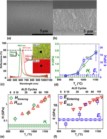
Figures 1(a) and 1(b) show the top-view and cross-sectional SEM images of 254 nm NCCs, indicating good particle monodispersity and highly ordered structure. The SEM images of 289 nm NCCs (see Fig. 1 of Ref. Reference Zhang, Zhang, Lee, Cheng and Feng39 for the same NCCs) also indicate high crystal quality. Moreover, the quality of each NCC can be evaluated by the maximum intensity I max of the Bragg reflectance peak in reflectance spectrum, and I max ≥ 80% normally indicates very high crystal quality. Reference Míguez, Yang, Tétreault and Ozin44,Reference Lorenz, Zeckzer, Hilpert, Grau, Johansen and Leipner62 Figure 1(c) shows I max = 87% and I max = 80% for 254 and 289 nm NCCs, respectively, again indicating very high crystal quality. Reference Gallego-Gomez, Blanco and Lopez40,Reference Gallego-Gómez, Blanco and López63 Here, the position of (111) and Bragg peaks of a FCC crystal at the normal incidence condition can be calculated by Reference Gallego-Gomez, Blanco and Lopez40,Reference Gallego-Gómez, Blanco and López63
 $$\lambda = 2{d_{111}}{n_{{\rm{eff}}}} = 2\sqrt {{2 \over 3}} d\sqrt {n_{\rm{p}}^2\phi + n_{\rm{m}}^{\bf{2}}\left( {{\rm{1}} - \phi } \right)} \quad ,$$
where d is particle diameter; d 111 = d√(2/3) is the (111) plane spacing; n eff is the effective refractive index; ϕ is particle volume fraction (∼0.74 for FCC packing); n p and n m are the refractive indices of the SiO2 nanoparticles (∼1.425) Reference Chiappini, Armellini, Chiasera, Ferrari, Jestin, Mattarelli, Montagna, Moser, Nunzi Conti, Pelli, Righini, Clara Gonçalves and Almeida64,Reference Garcia-Santamaria, Miguez, Ibisate, Meseguer and Lopez65 and the air medium (∼1.0), respectively. Thus, based on Eq. (1), the theoretical peak positions for 254 ± 19 and 289 ± 13 nm NCCs would be 551 ± 41 and 627 ± 28 nm, respectively, matching nicely with the experimental results (569.2 and 617.3 nm) shown in Fig. 1(c).
(a) Top-view and (b) cross-sectional SEM images of a 254 nm NCC. (c) The reflectance spectra of 254 and 289 nm NCCs. The inserted images are the testing spots for the reflectance spectra in 254 and 289 nm NCCs. The spot size is 25 × 25 µm. (d) Hardness H and modulus E of 254 nm NCCs versus sintering temperature T s. (e) H and (f) E of 254 nm NCCs versus T s (bottom coordinate) and ALD cycles (top coordinate) in log–log plot. The corresponding values of untreated 254 nm NCC are shown as horizontal dash lines, and each error bar is shown as a shaded region.

The as-assembled 254 nm NCCs have hardness H of 0.05 ± 0.01 GPa and modulus E of 1.6 ± 0.2 GPa. Figure 1(d) shows the H and E of untreated and sintered 254 nm NCCs, indicating that 850 °C is the minimum temperature required to achieve appreciable mechanical reinforcement after 1-h-sintering, consistent with the literature results. Reference Zhou, Li, Ye, Liu, Wang, Zhao, Jiang and Song11,Reference Miguez, Blanco, Lopez, Meseguer, Yates, Pemble, Lopez-Tejeira, Garcia-Vidal and Sanchez-Dehesa13–Reference Gouvêa and Castro18,Reference Zakhidov, Baughman, Iqbal, Cui, Khayrullin, Dantas, Marti and Ralchenko21–Reference Kubo, Gu, Takahashi, Fujishima, Segawa and Sato29,Reference Li, Wang, Pan, Cui, Xu, Wang, Song and Jiang42 Sintering duration is also important, e.g., the 3-h-850 °C sintered NCC has H = 0.26 ± 0.12 GPa and E = 2.4 ± 1.15 GPa, almost equivalent to those (H = 0.29 ± 0.07 GPa, E = 3.1 ± 1.4 GPa) with 1-h-950 °C treatment, and significantly larger than those (H = 0.13 ± 0.04 GPa, E = 0.9 ± 0.3 GPa) with 1-h-850 °C treatment.
To directly compare the effects of ALD and sintering, Fig. 1(e) is plotted by empirically power-law-correlating T s and ALD-cycle n that result in the same hardness, which gives T s = 670n 1/9. The same correlation (T s = 670n 1/9) is applied to plot the moduli E of sintered and ALD-treated NCCs as a function of temperature and n, respectively [Fig. 1(f)]. Figures 1(e) and 1(f) indicate that both H and E exponentially increase with increasing T s and n. For example, for T s = 1100 °C, H and E increase 3700 and 900%, respectively, compared to those of as-assembled NCCs. At 120ALD, H and E increase 6400 and 1830%, respectively.
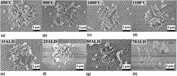
The hardening and stiffening of NCCs are due to the development of IPB. Reference Zhang, Zhang, Lee, Cheng and Feng38–Reference Gallego-Gomez, Blanco and Lopez40 As shown in Figs. 2(a) and 2(e), the indentation on 850 °C-sintering and 15ALD 254 nm NCCs result in a rigid-granule-like behavior without permanent deformation of individual NCs, resembling the indents on as-assembled NCC [see Fig. S1(a) in Supplementary Material]. Reference Zhang, Zhang, Lee, Cheng and Feng38–Reference Gallego-Gomez, Blanco and Lopez40 The granular behavior indicates weak IPB. Figure 2 also shows that, by increasing T s or ALD cycle number, the permanent deformation and/or fracture of individual NCs are increasingly pronounced, especially when T s ≥ 1000 °C and ALD-cycle ≥ 50, indicating substantially stronger IPB.
SEM images of ∼1 μm indents on (a)–(d) sintered and (e)–(h) ALD-treated 254 nm NCCs. The sintering temperature and #ALD are labeled. Here, each vertical pair [e.g., (a) and (e)] correspond roughly to the same hardness.

Figure 2 interestingly shows that, the indentation of ALD-treated and sintered NCCs with the same hardness results in similar morphology, suggesting that IPB is increased in both cases. Thus, by increasing IPB through either sintering or ALD, the NCC deformation mechanism transitions from the granular behavior with weak IPB [see Figs. 2(a) and 2(e)] to granular behavior with strong IPB [see Figs. 2(c) and 2(g)], and then to monolith-like behavior [see Figs. 2(d) and 2(h)]. This mechanism transition in sintered and ALD-treated NCCs agrees well with our previous study on ALD-treated NCCs, Reference Zhang, Zhang, Lee, Cheng and Feng39 which is also consistent with the observation of Gallego-Gómez et al. Reference Gallego-Gómez, Morales Flórez, Blanco, de la Rosa Fox and López10,Reference Gallego-Gomez, Blanco and Lopez40 that the NCC's behavior would transit from granular to nongranular/monolithic after CVD infiltration into the NCC structure.
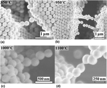
The sintering-induced IPB can be qualitatively confirmed by the formation of freestanding NC-chains inside a sintering-induced crack as shown in Fig. 3. No such NC-chain is observed in the as-assembled NCCs [see Fig. S1(b) in Supplementary Material]. It is interesting that the interparticle necking becomes observable only at T s ≳ 1000 °C, corresponding to strong IPB as implied by Figs. 2(c) and 2(d), which is consistent with Poppe's observation for 1.556 μm SiO2 MCs. Reference Poppe33 We believe that, for T s in the range of 850–1000 °C, the interparticle necking is also formed, as implied by the formation of freestanding NC-chains [see Figs. 3(a) and 3(b)] and also the hardening and stiffening of the NCCs [see Fig. 1(d)], but the size of the necking is below the resolution/image-noise limit of SEM.
SEM images of 1-h-sintering-induced cracking gaps, showing freestanding NC chains. The sintering temperatures are labeled.

It should be also noted that, as shown in Fig. 1(f), for NCCs that have comparable hardnesses, ALD treatment induces higher modulus than sintering; that is, ALD is more effective in stiffening than sintering, which may be qualitatively understood by the fact that Al2O3 ALD introduces a stiffer second phase (Al2O3) into SiO2 NCCs, i.e., an additional stiffening effect compared to sintering. To quantitatively investigate this additional stiffening effect on NCCs due to the second phase introduced by ALD, Reference Zhang, Prosser, Feng and Lee8 using various ALD materials would be needed, Reference Zhang, Prosser, Feng and Lee8 which will be left for a future work.
In the following, we want to discuss the effects of sintering and ALD on suppressing NCCs' unstable deformation. As-assembled NCCs show unstable deformation, manifested as pop-ins upon nanoindentation. Reference Gallego-Gómez, Morales Flórez, Blanco, de la Rosa Fox and López10,Reference Zhang, Zhang, Lee, Cheng and Feng38,Reference Gallego-Gomez, Blanco and Lopez40 In our previous study, Reference Zhang, Zhang, Lee, Cheng and Feng38 we found that the ALD-treatment significantly suppresses the unstable deformation. Here, we will show that sintering introduces a very similar effect.
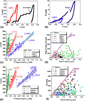
Figures 4(a) and 4(b) show the typical indentation load–displacement (P–h) curves for the as-assembled as well as the sintered and ALD-treated NCCs of 3 conditions as labeled, indicating multiple pop-ins. A pop-in is a sudden increase of displacement without the associated load increase. Reference Lorenz, Zeckzer, Hilpert, Grau, Johansen and Leipner62,Reference Chrobak, Nordlund and Nowak66,Reference Wright, Saha and Nix67 Gallego-Gómez et al. Reference Gallego-Gómez, Morales Flórez, Blanco, de la Rosa Fox and López10 also observed pop-ins upon indenting 335 nm SiO2 NCCs. We have discussed the mechanism transition of pop-ins in untreated NCCs in a separated paper. Reference Zhang, Zhang, Lee, Cheng and Feng38 It was found that, by deepening indentation, the unstable deformation mode of untreated NCCs transitions from NC dislodging to shear band formation. Reference Zhang, Zhang, Lee, Cheng and Feng38
Load P versus displacement h for (a) untreated and 950 oC-sintered and (b) 50ALD and 1000 oC-sintered 254 nm NCCs. The pop-in-start displacement h s and pop-in-end displacement h e of 1st pop-in versus the 1st pop in load P 1st for (c) sintered and (e) ALD-treated 254 nm NCCs, where the slopes ηs (=dh s/dP 1st) and ηe (=dh e/dP 1st) are also labeled for each sample. Pop-in size Δh (=dh e − dh s) versus h s for (d) sintered and (f) ALD-treated 254 nm NCCs. Here, for easy comparison, we choose the same symbols for each sintering condition in (d) and the corresponding #ALD in (f) with the similar hardness.

Figures 4(c) and 4(e) plot the pop-in initiation/start displacement h s and pop-in-termination/end displacement h e as a function of the load of the 1st pop-in P 1st for ALD-treated and sintered samples, respectively. Figures 4(c) and 4(e) show that, for each treatment condition, h s, h e and Δh (=h e − h s) of the 1st pop-in are roughly proportional to P 1st. Moreover, Figs. 4(c) and 4(e) show that h s, h e and Δh at the same P 1st decreases significantly by increasing ALD cycle or sintering temperature, indicating that both sintering and ALD treatments suppress the unstable deformation of NCCs. Reference Zhang, Zhang, Lee, Cheng and Feng38 The same trend is observed for all treatment conditions considered in this study [see Figs. S2(a) and S2(b) in Supplementary Material]. It should be mentioned that, because the 1 and 2 µm indentation depths are relatively shallow, according to our previous work, Reference Zhang, Zhang, Lee, Cheng and Feng38 the pop-ins would fall into the particle-dislodging regime, which is consistent with the indentation morphology shown in Fig. 2.
The slope ηs (=dh s/dP 1st) of h s of each sample is also labeled in Figs. 4(c) and 4(e). It is interesting to see that, for reinforced NCCs with similar hardness, the values of ηs are very close to each other by comparing the plots of each sintering-ALD pair (e.g., 1.22–1.32 for 25ALD-950 °C, or 0.48–0.56 for 50ALD-1000 °C), implying that sintering and ALD treatments experience similar reinforcement mechanism. This similarity is consistent with the conclusion based on the indent morphology similarity (see Fig. 2). Moreover, as labeled in Figs. 4(c) and 4(e), the slopes ηe (=dh e/dP 1st) of h e have the same trend (e.g., 1.64–1.7 for 25ALD-950 °C, or 0.56–0.64 for 50ALD-1000 °C) by comparing the plots of each sintering-ALD pair.
Figures 4(d) and 4(f) show the plots of Δh versus h s for all recorded pop-ins for sintered and ALD-treated samples, respectively, showing a roughly common upper Δh envelope of Δh max ≈ 0.6h s for T s ≤ ∼1000 °C or ALD cycle ≤ ∼25. Moreover, Fig. 4(f) shows that the Δh envelop drops well below 0.6h s for 50ALD, and Fig. 4(d) shows only a very few small (<100 nm) pop-ins for T s = 1100 °C. In fact, the pop-in phenomenon completely disappears at 78ALD for ALD-treated samples. Consequently, T s > 1100 °C or ALD cycle > 50 can significantly suppress or completely eliminate the unstable deformation of NCCs. The trend of Δh envelope indicates again that the deformation mechanism is undergoing the following transition: from granular behavior with weak IPB (T s < 1000 °C or ALD cycle < 50) to granular behavior with strong IPB (T s ≈ 1000 °C or ALD cycle ≈ 50), and then to monolith-like behavior (T s ≥ ∼1100 °C or ALD cycle ≥ ∼78). The pop-in behavior of sintered and ALD-treated 254 nm NCCs matches nicely with the results of our previous study on ALD-treated 289 nm NCCs. Reference Zhang, Zhang, Lee, Cheng and Feng38
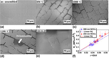
In summary, both sintering and ALD treatments can locally harden and stiffen NCCs and at the same time suppress the unstable deformations of NCCs. However, in the following, we discuss a serious issue associated to sintering—that is, cracking which significantly degrades the film-integrity and functionality. Reference Mayoral, Requena, Moya, López, Cintas, Miguez, Meseguer, Vázquez, Holgado and Blanco14–Reference Míguez, Meseguer, López, Blanco, Moya, Requena, Mifsud and Fornés17,Reference Gates, Park and Xia19 On the contrary, we find that the ALD-treatment can harden, stiffen, and also simultaneously toughen the NCC without inducing further cracks.
Figure 5(a) shows that cracks may form in as-assembled NCCs due to capillary stress during solvent evaporation in the self-assembly process, Reference Tirumkudulu and Russel68–Reference Singh and Tirumkudulu70 which however has minimal impact on the optical properties of NCCs Reference Van Le, Ross, Velarde, Legg and Wirth16,Reference Míguez, Meseguer, López, Blanco, Moya, Requena, Mifsud and Fornés17,Reference Kuai, Badilescu, Bader, Brüning, Hu and Truong24 likely due to the small gaps present in these cracks [see Fig. 5(a)]. As aforementioned, sintering has been used to reinforce inorganic NCCs. Reference Zhou, Li, Ye, Liu, Wang, Zhao, Jiang and Song11,Reference Miguez, Blanco, Lopez, Meseguer, Yates, Pemble, Lopez-Tejeira, Garcia-Vidal and Sanchez-Dehesa13–Reference Gouvêa and Castro18,Reference Zakhidov, Baughman, Iqbal, Cui, Khayrullin, Dantas, Marti and Ralchenko21–Reference Kubo, Gu, Takahashi, Fujishima, Segawa and Sato29,Reference Li, Wang, Pan, Cui, Xu, Wang, Song and Jiang42 However, Figs. 5(b) and 5(d) clearly show that, due to the densification-induced residual biaxial-tensile stress, Reference Jagota and Hui71 sintering significantly widens the primary cracks formed during self-assembling and at the same time creates and widens secondary cracks. The crack widening effect becomes significant [see Fig. 5(b)] even at 850 °C (i.e., the minimum T s for effective sintering), and the effect becomes increasingly severe upon further increasing T s. For example, for T s = 1000 °C, some crack gaps can be wider than 10 μm, which is equivalent to the thickness of the NCC. It is well known that the sintering-induced cracks can seriously jeopardize the optical properties of NCCs. Reference Van Le, Ross, Velarde, Legg and Wirth16,Reference Míguez, Meseguer, López, Blanco, Moya, Requena, Mifsud and Fornés17,Reference Kuai, Badilescu, Bader, Brüning, Hu and Truong24
(a)–(e) SEM images of as-assembled, sintered and ALD-treated NCCs as labeled. Here, in (d), a 2-μm-indentation-induced film delamination can be seen in the middle (one piece of film together with the indent on it was delaminated and missing as labeled). The scale bar is 50 µm in (a–e). (f) Fracture toughness K c versus the normalized ALD thickness τ = t/(d/2) for ALD-treated 289 and 254 nm NCCs based on the WDWC indentation-induced cracks, where t is the ALD thickness (=#ALD × 0.07 nm/cycle), and d/2 is the particle radius.

Besides creating and widening cracks, sintering also significantly lowers NCCs' resistance to external penetration due to residual biaxial tensile stress. Reference Kuai, Badilescu, Bader, Brüning, Hu and Truong24,Reference Grabner72 For example, for T s > 850 °C, any indentation larger than 2 µm in depth induces unstable and severe cracks propagation extending all the way to the NCC domain boundary and/or film delamination [see Fig. 5(d)].
In stark contrary, ALD reinforces NCCs because of the second phase material infiltration, which does not induce residual tensile stress. Consequently, the ALD-treatment (even at 144ALD) does not widen the primary cracks formed during self-assembly as shown in Fig. 5(e).
To quantify the toughening effect of ALD treatment, the fracture toughness K c is determined based on indentation-induced half-penny cracking, which can be calculated by Reference Lawn, Evans and Marshall73,Reference Lee, Gao, Johanns and Pharr74
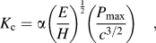 $${K_{\rm{c}}} = \alpha {\left( {{E \over H}} \right)^{{1 \over 2}}}\left( {{{{P_{{\rm{max}}}}} \over {{c^{3/2}}}}} \right)\quad ,$$
where P max is the peak indentation load, E is Young's modulus, H is the hardness, and c is the surface-trace length of the half penny crack (see Fig. S4 for indentation-induced cracks for a 144ALD treated 289 nm NCC) measured from the indent center. Reference Volinsky, Vella and Gerberich75–Reference Hardinga, Olivera and Pharra78 α is an empirical constant depending on the indenter geometry and is 0.032 for a cube-corner indenter. Reference Volinsky, Vella and Gerberich75–Reference Hardinga, Olivera and Pharra78
None of the 2 μm indentations on as-assembled 254 nm NCCs show indentation-induced cracks, so we could not calculate K c. On the other hand, it is surprising to see that, at the nominally same 2 μm indentation, the as-assembled 289 nm NCCs show bimodal indentation fracture behavior: ∼40% indentations show no cracks [see Fig. S3(b)], while others (∼60% indentations) introduce very long cracks [see Fig. S3(a)] which are normally not terminated until intersecting with the intrinsic cracks (i.e., domain boundaries).
This bimodal indentation fracture behavior may be resulted from the different residual capillary (RC) stress in different film domains [see Figs. S3(a) and 5(a)]. Here, intrinsic cracks developed during drying process relax the capillary stress and define the domains. However, RC stress may exist and be different from domain to domain. Particularly, in some domains, the RC stress may be still large enough to provide high driving force for cracking, so these domains are prone to initiating and expanding cracks upon indentation [see Fig. S3(a)]. Reference Anunmana, Anusavice and Mecholsky79,Reference Zeng and Rowcliffe80 On the other hand, in some other domains, the RC stress may be close to zero, and Fig. S3(b) implies that the indentation-induced stress alone is not enough to initiate any cracks. Thus, the driving force for the long cracks [see Fig. S3(a)] may involve both the indentation and RC stresses, Reference Anunmana, Anusavice and Mecholsky79,Reference Zeng and Rowcliffe80 so we could not use Eq. (2) which is valid for cracking due to indentation stress alone.
Therefore, we cannot conclusively determine K c for the as-assembled NCCs. Although increasing P max would increase the crack length and possibility of indentation cracking, Reference Volinsky, Vella and Gerberich75,Reference Pharr76 the substrate's influence to the indentation stress field for our NCCs (∼10 μm thick) may become significant if further increasing the indentation depth from 2 μm.
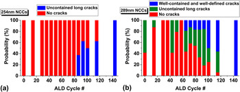
Figure 6 shows the probabilities of three indentation-induced cracking modes for as-assembled and ALD-treated NCCs: (i) no cracking [e.g., Fig. S3(b)], (ii) uncontained long cracking [e.g., Fig. S3(a)], and (iii) well-defined and well-contained (WDWC) indentation-induced cracking (e.g., Fig. S4). Figure 6 indicates that, for #ALD < 65, each of the ALD-treated 254 and 289 nm NCCs behaves similar to its as-assembled counterpart, i.e., none of the 254 nm NCCs show indentation-induced cracking while many of the 289 nm NCCs show the bimodal indentation fracture behavior.
The probabilities of three indentation-induced cracking modes for as-assembled and ALD-treated NCCs composed of (a) 254 nm NCs and (b) 289 nm NCs: (i) no cracking, (ii) uncontained long cracking, and (iii) WDWC indentation-induced cracking.

Figure 6 also interestingly shows that, for 65 ≤ #ALD ≤ 80, some indentations on 289 nm NCCs induce WDWC indentation-induced cracks, while the 254 nm NCCs still show no indentation-induced cracking. Then, for #ALD > 80, some indentations on both 254 and 289 nm NCCs show WDWC cracks whose probability generally increases with increasing #ALD; in fact, all indentations on the 144ALD 254 and 289 nm NCCs show WDWC cracking.
It should be noted that, while some indentations on the as-assembled and ALD-treated 289 nm NCCs show very long uncontained indentation-induced cracks even at up to 115ALD, none of the as-assembled and ALD-treated 254 nm NCCs show this type of long cracks. Thus, according to the aforementioned mechanism of RC stress assisted cracking, Reference Anunmana, Anusavice and Mecholsky79,Reference Zeng and Rowcliffe80 the 254 nm NCCs may be at an overall more relaxed condition with minimal RC stress compared to the 289 nm NCCs, and the calculation of K c and the observation of fracture behavior for 254 nm NCCs would be more intrinsic with negligible influence from the RC stress.
Based on these WDWC cracks, the K c values for 289 and 254 nm NCCs were calculated using Eq. (2) and plotted versus the ALD-thickness t normalized by particle radius [τ = t/(d/2)] Reference Zhang, Zhang, Lee, Cheng and Feng39 [see Fig. 5(f)]. Figure 5(f) indicates statistically good matching between the K c values for 289 and 254 nm NCCs, probably because each domain in the 289 nm NCCs showing WDWC cracks is already in almost fully relaxed condition (similar to that for 254 nm NCCs as aforementioned). Thus, Fig. 5(f) may be considered as a master K c curve for Al2O3 ALD-treated SiO2 NCCs composed of monodisperse NCs of the two particle sizes.
Figure 5(f) shows that K c is roughly proportional to #ALD for 0.03 < τ < 0.08, implying that, if K c always monotonically increases with τ, K c ≈ 0.156 ± 0.071 MPa m1/2 at τ = 0.031 would be a large overestimate for the as-assembled NCCs' K c. Thus, Fig. 5(f) implies that, compared to the untreated NCCs, the ALD treatment at τ ≈ 0.08 would toughen the NCCs by much larger than 300%, which is a large toughening effect.
It should be mentioned that, it is very difficult to measure the facture toughness for NCCs after sintering because the material become too brittle for reliable measurement. For instance, 1 µm indentations did not generate crack [see Figs. 2(a) and 2(d)], whereas each 2 µm indentation caused severe cracking of an entire NCC domain or complete delamination of the NCC film [see Fig. 5(d)]. This result again indicates the limitation of sintering as a mechanical reinforcement method for NCCs due to the embrittlement effect.
IV. CONCLUSIONS
Silica NCCs were systematically treated using sintering and Al2O3 ALD and then characterized by nanoindentation. Both sintering and ALD treatments can locally harden and stiffen the NCCs. The IPB strength increases with increasing the sintering temperature and ALD-cycle number. One major difference between the two reinforcement methods lies in the crack formation upon treatment. While sintering suffers from serious cracking issues significantly degrading the integrity of NCCs, ALD-treatment can simultaneously harden, stiffen, and toughen the NCCs without inducing any secondary cracking. By using ALD treatment, the toughness of NCCs can increase much larger than 300% compared to the as-assembled NCC. This finding highlights the versatility of ALD as a reinforcement method for nanoparticle assemblies and potentially nanoporous materials.
Supplementary Material
To view supplementary material for this article, please visit http://dx.doi.org/jmr.2015.347.
ACKNOWLEDGMENTS
G. Feng acknowledges financial support from an NSF Award (CBET-1235769). D. Zhang is supported by a Villanova University Research Scholarship. D. Lee acknowledges financial support from an NSF CAREER Award (DMR-1055594) and the PENN MRSEC DMR11-20901 through the NSF. We thank C. Townend for helping on designing and machining the NCC-fabrication cell. We also appreciate the technical supports from J. Hay and G. Min of Keysight Technologies Inc. (formerly Agilent Technologies Electronic Measurement Division) as well as from K. Park and W. Oliver of Nanomechanics, Inc. We also want to thank Eric Johnston of Singh Center for Nanotechnology at the University of Pennsylvania for allowing us to use a Filmetrics 40 system. Moreover, we want to appreciate the help and sample evaluation from Jim Elman of Filmetrics Inc.