I. INTRODUCTION
Due to their one-dimensional structure and outstanding anisotropic properties, nanocylinders including carbon nanotubes, inorganic nanorods, and cellulose liquid crystals have all garnered significant interest as building blocks for larger structures. However, improved understanding and control over their bottom-up assembly are needed to enable their outstanding nanoscale properties to be manifested in macroscale materials. Processing of nanocylinder dispersions is quickly becoming established as a key research area for the hierarchical bottom-up assembly of anisotropic nanomaterials into functional devices such as transistors,Reference Ko and Tsukruk1 macroelectronic devices,Reference Duan2 sensors,Reference Murphy, San, Gole, Orendorff, Gao, Gou, Hunyadi and Li3–Reference Lee, Wood and Belcher7 electro-optical devices,Reference Murphy, San, Gole, Orendorff, Gao, Gou, Hunyadi and Li3, Reference Li and Alivisatos8–Reference Li, Walda, Manna and Alivisatos10 and structural materials.Reference Vigolo, Poulin, Lucas, Launois and Bernier11–Reference Davis, Ericson, Parra-Vasquez, Fan, Wang, Prieto, Longoria, Ramesh, Saini, Kittrell, Billups, Adams, Hauge, Smalley and Pasquali24 Key advantages to a fluid-phase processing approach are that considerable knowledge and infrastructure already exist as a result of the polymer industry. The US coatings industry alone was worth 24 billion dollars in 2007,25 and solution spinning of liquid crystalline solutions of rodlike polymers is well known for producing high performance materials such as DuPont Kevlar.
While the chemical and physical properties of nanocylinders vary broadly, their cylindrical shape results in a common framework for viewing their phase behavior, shear response, and assembly into bulk materials. All rodlike materials have the inherent tendency to form lyotropic liquid crystalline phases at sufficient concentration, and many theories for liquid crystalline phase behavior do not distinguish between cylindrically shaped colloids and rodlike polymers.Reference Green, Behabtu, Pasquali and Adams26 Davidson et al.,Reference Davidson, Batail, Gabriel, Livage, Sanchez and Bourgaux27 Solomon and Spicer,Reference Solomon and Spicer28 and others have highlighted that research into the phase behavior and rheological properties of all cylindrical materials can be advanced by viewing them through the framework initially established for rodlike polymers. In spite of this, the majority of research on liquid crystalline assembly has focused on organic entities, particularly polymers. As of the early 1990s, fewer than 20 inorganic liquid crystals composed entirely of inorganic moieties had been discovered,Reference Davidson, Batail, Gabriel, Livage, Sanchez and Bourgaux27 and carbon nanotube research was in its infancy. Over the last ten to twenty years, increasing capabilities in nanomaterial synthesis and characterization have created considerable interest in bottom-up assembly of recently discovered synthetic nanomaterials in fluids. In parallel, nanotechnology has spurred new investigations of previously explored materials including cellulose nanorods, cylindrical clays, and rodlike viruses. Increased understanding of the liquid crystalline phase behavior of nanocylinders promises to not only provide new insights into liquid crystalline science, but also to facilitate ongoing applications development.
This review focuses on liquid crystalline phase formation from nanocylinder (e.g., nanotube, nanorod, nanowire) dispersions. It explores the common challenges and achievements of nanocylinder liquid crystals by focusing on three types of systems (i) carbon nanotubes, (ii) inorganic nanocylinders, and (iii) cellulose nanocrystals. These systems were chosen because they exemplify synthetic and naturally occurring nanocylinders with a broad range of aspect ratios and chemistries. These materials have also been the focus of a significant proportion of the work on lyotropic nanocylinder liquid crystals. However, there are equally important contributions to liquid crystalline science based on rodlike viruses,Reference Lee, Wood and Belcher7, Reference Dogic, Purdy, Grelet, Adams and Fraden29–Reference Flynn, Lee, Peelle and Belcher33 nanoplatelets,Reference Phillips and Schmidt34–Reference Bisoyi and Kumar36 and incorporating nanocylinders into existing liquid crystalline matricesReference Phillips and Schmidt34–Reference Bisoyi and Kumar36 that are beyond the scope of this review.
II. BACKGROUND
Liquid crystals have the fluidity of a liquid and the order of a solid. There are two primary types of liquid crystals: thermotropic and lyotropic. Thermotropic liquid crystals are composed of small molecules with rigid cores; their phase transitions result from changes in temperature. Lyotropic liquid crystals consist of anisotropic macromolecular entities dispersed in a solvent. In lyotropic liquid crystals, phase transitions are driven by changing the concentration of an anisotropic mesogen in a solvent. Within these two main categories, three primary FriedelanReference Donald and Windle37 classes based on liquid crystalline microstructure have been defined (i) nematic, where rodlike molecules are oriented along a director and there is long range orientational order, but only short range positional order; (ii) cholesteric (chiral nematic) in which the nematic microstructure is twisted along an axis perpendicular to the director; and (iii) smectic, which has both long range orientational and long range positional order. It should be noted that due to the long relaxation times associated with macromolecular mesogens, liquid crystals can have a globally isotropic polydomain structure where each domain has a different director. In these systems, homogenous ordering, resulting from the annealing of defects between domains, can take months or years to complete. Fortunately, this process can be accelerated by application of shear, magnetic, or electric fields.Reference Donald and Windle37, Reference Larson38
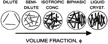
There are several continually evolving theoretical frameworks for considering lyotropic liquid crystal phase behavior. In all of these frameworks, the length to diameter ratio L/D, known as the aspect ratio, is a key determinant of phase boundaries. In general, as depicted in Fig. 1, at low concentration, rods form a dilute phase where they can rotate and translate freely due to Brownian motion. While Brownian motion is typically associated with small low aspect ratio materials, it has been shown that 500 nm long (L/D ≈ 500) single-walled carbon nanotubesReference Davis, Ericson, Parra-Vasquez, Fan, Wang, Prieto, Longoria, Ramesh, Saini, Kittrell, Billups, Adams, Hauge, Smalley and Pasquali24, Reference Duggal and Pasquali39 and germanium nanowires up to 10 μm in length with diameters ranging from 7 to 25 nm (L/D ≈ 500)Reference Marshall, Davis, Lee and Korgel40 undergo Brownian motion in low viscosity solvents. As rod concentration is increased, the system becomes semidilute where rotation becomes inhibited. At still higher concentration, an isotropic concentrated phase should be reached where rod motion is confined to small volumes. When a critical rod concentration ϕI is reached, the system becomes biphasic; some of the rods form an anisotropic phase in equilibrium with the isotopic phase. With increasing concentration in the biphasic region, the proportion of the anisotropic phase increases while the proportion of the isotropic phase decreases until the system becomes completely liquid crystalline at a second critical concentration ϕN. For ideal, monodisperse hard rods, the concentration in the isotropic and liquid crystalline phases will remain constant regardless of the total rod concentration. However, the concentrations of each phase can be a function of the total rod concentration as a result of either rod dimension polydispersityReference Green, Parra-Vasquez, Behabtu and Pasquali41 or electrostatic interactionsReference Dong, Kimura, Revol and Gray42 which can alter the effective diameter and the extent to which the nanocylinders are individually dispersed.
Phase behavior of fluid dispersed rods. Reprinted with permission from Davis et al.Reference Davis, Ericson, Parra-Vasquez, Fan, Wang, Prieto, Longoria, Ramesh, Saini, Kittrell, Billups, Adams, Hauge, Smalley and Pasquali24 Copyright 2004 American Chemical Society.

There is not currently a widely accepted universal theory for modeling and predicting the phase behavior of nanocylinder liquid crystals; ongoing refinements to fundamental scientific understanding are an area of active research. Most theories are based on at least one of three fundamental frameworks: Onsager theory,Reference Onsager43 Flory theory,Reference Flory44 or Derjaguin–Landau–Verwey–Overbeek (DLVO) theory.Reference Israelachvili45 According to Onsager’s seminal 1949 theoryReference Onsager43 liquid crystalline phase formation occurs because the gain in translational entropy resulting from alignment is greater than the loss of orientational entropy. Based on Onsager’s original theory for monodisperse spherocylinders with only hard-rod interactions, the isotropic-biphasic transition occurs at ϕI = 3.34/(L/D) and the biphasic-nematic transition occurs at ϕN = 4.49/(L/D) where L is the rod length and D is the diameter. The volume fraction ϕ of the rod can be calculated from the relative density of the solvent and rod.


where w is the weight fraction of the rod. Since most real systems are polydisperse and have interactions, there have been numerous extensions to this initial theory to account for interactions with the solventReference Khokhlov and Ciferri46, Reference Khokhlov and Semenov47 and polydispersity.Reference Speranza and Sollich48–Reference Wensink and Vroege50 In general, both poor solvent quality and polydispersity widen the biphasic region.
Flory theory,Reference Flory44 originally published a few years after Onsager theory, considers the potential location of rods on a lattice. Based on this theory for noninteracting monodisperse spherocylinders ϕI = (8/(L/D))(1 – 2(L/D) and ϕN = 12/(L/D). Refinements to Flory theory include the well known Flory-Huggins Interaction parameter χ to account for solvent quality. Flory theory is commonly used for rodlike polymer liquid crystalline phase behavior,Reference Flory44, Reference Abe, Balluff and Ciferri51 but since many nanocylinder systems adhere more closely than polymers to Onsager’s original assumptions of rigidity and “infinite length” (L>>D), there has been renewed interest in Onsager theory and subsequent refinements.
Finally, since van der Waals, electrostatic, steric, and depletion interactions cannot be neglected when considering nanocylinder dispersion thermodynamics, DLVO theory and other fundamental principles of colloid science are needed to elucidate the interactions between rods. This approach has been used for a number of studies of charged rods.Reference Davidson, Batail, Gabriel, Livage, Sanchez and Bourgaux27, Reference Maeda and Maeda52–Reference Lemaire, Davidson, Petermann, Panine, Dozov, Stoenescu and Jolivet54 However, coupling these principles with orientation distribution functions often requires making numerous assumptions that can make correlating theoretical predictions to experimental results challenging.Reference Dogic, Purdy, Grelet, Adams and Fraden29, Reference Lemaire, Davidson, Petermann, Panine, Dozov, Stoenescu and Jolivet54
III. CARBON NANOTUBES
Carbon nanotubes are perhaps one of the most widely studied lyotropic nanocylinder systems. Single-walled carbon nanotubes (SWNTs) can be considered as a rolled sheet of graphene, where the direction of rolling, known as the chirality, determines the density, and electronic character. Multi-walled carbon nanotubes (MWNTs) consist of nested cylinders, and may be referred to as double-walled (DWNT) or few-walled (FWNT) to distinguish these structures from their larger counterparts. Carbon nanotubes, particularly SWNTs, have been the subject of considerable research; the combination of their one-dimensionality and sp 2 hybridization results in outstanding mechanical, electrical, and thermal properties. SWNTs have up to 60 times the strength of steel at 1/6th the weight and better thermal conductivity than diamond. In addition, depending on chirality, they can either be semiconducting or metallic with ballistic conductance and high current carrying capacity.Reference Baughman, Zakhidov and de Heer16 Dispersing carbon nanotubes in fluids at sufficient concentration for liquid crystalline phase formation is a considerable challenge. The small diameter and molecular perfection of carbon nanotubes causes them to be amphiphobic; their dispersion requires overcoming the 500 eV/μm between tubes.Reference Thess, Lee, Nikolaev, Dai, Petit, Robert, Xu, Lee, Kim, Rinzler, Colbert, Scuseria, Tomanek, Fischer and Smalley55
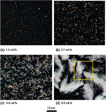
One approach for achieving lyotropic carbon nanotube liquid crystals is covalent modification. For example, Song and WindleReference Song, Kinloch and Windle56, Reference Song and Youn57 oxidized MWNTs by sonication in a mixture of sulfuric and nitric acids. This resulted in carboxylation and hydroxylation at the tube ends and defect sites,Reference Song, Kinloch and Windle56, Reference Banerjee, Hemraj-Benny and Wong58 and enabled sufficient electrostatic repulsion for dispersions of individual MWNTs. Two dispersions, one sonicated for 24 h (Dispersion A) and another sonicated for 12 h (Dispersion B), were produced and found to have distinctly different aspect ratio distrubutions. With increasing concentration, both dispersions transitioned from fully isotropic to biphasic to fully liquid crystalline. The isotropic-biphasic transition ϕI was approximated based on the appearance of bireflecting contrast (bright spots) in samples imaged under reflected cross polarized microscopy at low magnification (Fig. 2). It is important to note that both the number of concentrations investigated and the method used to determine ϕI will affect the value obtained; lower magnification optical methods may result in the observed value of ϕI being higher than the actual value. The isotropic-nematic phase transition ϕN was approximated based on the concentration at which the anisotropic phase became continuous. For Dispersion A, which had a number average aspect ratio of 30, the authors estimated that ϕI ≈ 1 vol% and ϕN ≈ 4 vol%. For Dispersion B, which had a number average aspect ratio of 40 and a wider distribution of lengths, an estimate of ϕI was not provided. However, the authors noted that the biphasic region was broader and ϕN ≈ 6.5 vol%. Liquid crystalline phase formation was further confirmed by the presence of characteristic Schlieren textures (Fig. 2) as well as nematic thread textures.Reference Donald and Windle37 As with most other carbon nanotube liquid crystals,Reference Zakri and Poulin59 the microstructure contained numerous defects. In subsequent work on oxidized MWNT dispersions, the defect structure was studied in detail based on scanning electron microscopy of dried drops,Reference Li, Zhu, Kinloch and Windle60 and further work characterized the selective partitioning of longer carbon nanotubes to the isotropic phase in accordance with theory.Reference Zhang, Kinloch and Windle61
Reflected cross polarized microscopy of oxidized MWNTs L/D ≈ 30 with increasing concentration. The number of birefringent domains increases with concentration and at high concentration Schlieren textures characteristic of nematic phase formation can be observed. Reprinted with permission from Song and Windle.Reference Song and Windle126 Copyright 2005 American Chemical Society.

A second approach to achieving carbon nanotube dispersions at sufficient concentration for liquid crystalline phase formation is the adsorption of other species onto their surfaces, often called noncovalent functionalization. Biomolecules are particularly attractive for noncovalent functionalization because of their green chemistry, biocompatibility, and multifunctionality.Reference Nepal, Balasubramanian, Simonian and Davis62 In fact, DNA is known to disperse higher concentrations of SWNTsReference Nepal, Geckeler, Geckeler and Rosenberg63, Reference Nepal, Sohn, Aicher, Lee and Geckeler64 than almost any other material apart from superacids. Badaire et al.Reference Badaire, Zakri, Maugey, Derre, Barisci, Wallace and Poulin65 first reported liquid crystalline phase formation in dispersions of unpurified HiPcoReference Bronikowski, Willis, Colbert, Smith and Smalley66 SWNTs (20% residual catalyst) and aqueous single-stranded (ssDNA) solutions by allowing the system to concentrate via evaporation. A ratio of 1:1 SWNT:ssDNA by weight was required to form a dispersion without visible aggregatesReference Barisci, Tahhan, Wallace, Badaire, Vaugien, Maugey and Poulin67; lower fractions of ssDNA were insufficient to stabilize the dispersion at a sufficient concentration for liquid crystalline phase formation. In contrast to previous work with surfactants, higher concentrations of ssDNA did not induce depletion aggregation.Reference Zakri and Poulin59, Reference Badaire, Zakri, Maugey, Derre, Barisci, Wallace and Poulin65, Reference Barisci, Tahhan, Wallace, Badaire, Vaugien, Maugey and Poulin67 As was the case for oxidized MWNTs in water, the SWNT:ssDNA system formed a nematic liquid crystal with a small domain size. Based on dynamic depolarized light scattering, the nanotubes were dispersed in bundles with 15 nm < D < 50 nm and 2.0 μm < L < 4.5 μm resulting in 40 < L/D < 300. The phase transitions were estimated based on the appearance of birefringent domains using low magnification transmitted cross-polarized optical microscopy; the authors estimated that wI ≈ 2 wt% and wN ≈ 4 wt% or ϕI ≈ 1.25 vol% and ϕN ≈ 2.5 vol% using a SWNT density ρSWNT = 1.3 g/cm.3 This resulted in a ratio of ϕN/ϕI = 2 compared to the theoretical value of 1.4 based on Onsager theory; this discrepancy was attributed to polydispersity.
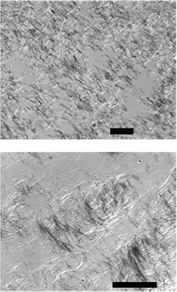
In more recent work, Ao et al.Reference Ao, Nepal, Aono and Davis68 demonstrated both nematic and cholesteric liquid crystalline phases can be formed by evaporating dispersions of purified HiPco SWNTs <L/D> ≈ 500 in aqueous double-stranded DNA (dsDNA). They hypothesized that since both dsDNA and SWNTs are mesogenic, a type of cooperative liquid crystal phase formation occurs during evaporation. Whether the helical structure of the dsDNA or the typical defected nematic structure associated with SWNTs dominated the microstructure depended on the dispersion preparation.Reference Ao, Nepal, Aono and Davis68 Dispersions of individual SWNTs resulted in cholesteric liquid crystals with similar pitch as dsDNA liquid crystals formed at higher concentration in the absence of SWNTs. In contrast, dispersions containing small bundles of SWNTs formed nematic liquid crystals with morphologies similar to that observed in other carbon nanotube systems. For example, as shown in Fig. 3(a), high magnification (120×) cross-polarized differential interference contrast (DIC) optical microscopy of the biphasic region revealed that the SWNT/dsDNA anisotropic phase formed seemingly endless strands of uniform diameter. This unusual microstructure was first reported in dispersions of SWNTs in 102% H2SO4 (2% excess SO3) in 2004 [Fig. 3(b)].Reference Davis, Ericson, Parra-Vasquez, Fan, Wang, Prieto, Longoria, Ramesh, Saini, Kittrell, Billups, Adams, Hauge, Smalley and Pasquali24
(Top) Strand-like “spaghetti” microstructure formed from dispersions of individual and small bundles of SWNT in dsDNA. (Bottom) Previously reported spaghetti morphology for SWNTs in 102% sulfuric acid. Scale bars are 20 μm in both images. Modified with permission from Davis et al.Reference Davis, Ericson, Parra-Vasquez, Fan, Wang, Prieto, Longoria, Ramesh, Saini, Kittrell, Billups, Adams, Hauge, Smalley and Pasquali24 Copyright 2004 American Chemical Society.

It is likely that additional liquid crystalline SWNT/biomolecule dispersions will be discovered as part of the growing interest in dispersion of synthetic nanocylinders in natural polyampholytes.Reference Nepal and Geckeler69 Dispersions of SWNTs in hyaluronic acid (HLA) have already been shown to form nematic liquid crystalline phases,Reference Moulton, Maugey, Poulin and Wallace70 and a higher SWNT:HLA ratio could be achieved than in SWNT:ssDNA. In fact, too large a proportion of HLA resulted in depletion interactions similar to those commonly seen in dispersions of SWNTs with synthetic surfactants. Interestingly, for SWNT dispersions, depletion interactions are generally viewed negatively, while for dispersions of cellulose and inorganic nanocylinders, depletion is increasingly viewed as a means of facilitating liquid crystalline phase formation. This difference is likely due to the exceptionally strong attractive interactions between SWNTs making it more likely that depletion will result in solid aggregates instead of the assembly of solvent lubricated aligned domains.
A third method of achieving carbon nanotube liquid crystals is dispersing the nanotubes in simple solvents. Bergin et al. reported the exfoliation of purified (6 wt% impurities) HiPco SWNT bundles, and the appearance of some birefringent domains, in γ-butyrolactone (GBL) at concentrations up to 0.5 mg/mL.Reference Bergin, Nicolosi, Giordani, de Gromard, Carpenter, Blau and Coleman71 Significantly higher concentration SWNT dispersions have been achieved in superacids, acids stronger than 100% sulfuric acid. To date, SWNT/superacids are the only carbon nanotube system for which a detailed phase diagram based on multiple characterization methods and a range of solvent qualities has been both empirically produced and substantiated by theoretical calculations. Initially, nematic phase formation in SWNTs dispersed in 102% H2SO4 was characterized based on birefringence, the ability to form multiple aligned species, and the presence of rheological signatures characteristic of rodlike polymer tumbling nematics.Reference Davis, Ericson, Parra-Vasquez, Fan, Wang, Prieto, Longoria, Ramesh, Saini, Kittrell, Billups, Adams, Hauge, Smalley and Pasquali24, Reference Marrucci and Ciferri72 The critical concentration ϕI was originally determined through high (over 100×) magnification cross polarized DIC optical microscopy. While this technique was less likely to overestimate ϕI than the more typically used low magnification optical microscopy or imaging of sealed vials, it was still subject to human error. The samples had to be carefully prepared by successive dilution in an anhydrous environment. In addition, finding the thin, strand-like (Fig. 3) domains formed by purified HiPco SWNTs in 102% H2SO4 at concentrations close to ϕI was challenging. A simpler and more accurate method was developed by Rai et al.Reference Rai, Pinnick, Parra-Vasquez, Davis, Schmidt, Hauge, Smalley and Pasquali73 using centrifugation in combination at UV-vis-NIR. In this method, the absorbance of the SWNT-superacid supernatants was used to directly calculate the maximum amount of SWNTs that could exist isotropically in a given solvent.
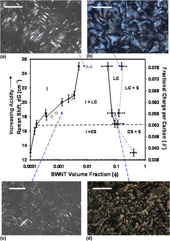
As was the case for rodlike polymer liquid crystals,Reference Kiss74 multiple approaches were also used for determining ϕN. These included finding the minimum concentration at which no isotropic regions were visible under cross polarized microscopy, the upper minimum in a plot of viscosity versus concentration at low shear rate,Reference Davis, Ericson, Parra-Vasquez, Fan, Wang, Prieto, Longoria, Ramesh, Saini, Kittrell, Billups, Adams, Hauge, Smalley and Pasquali24 and the disappearance of the solvent melting peak.Reference Zhou, Fischer, Heiney, Fan, Davis, Pasquali and Smalley75 Based on these methods, the phase diagram for SWNTs in mixtures of sulfuric (H2SO4) and chlorosulfonic (ClSO3H) was developed (Fig. 4). The overall SWNT/superacid phase diagram was similar to those developed by PapkovReference Papkov, Malkin and Kulichikin76 and others for rodlike polymers.Reference Donald and Windle37 However, there were several key distinctions from rodlike polymer phase behavior. First, below a critical solvent quality (acid strength) the SWNTs were not sufficiently stabilized, and the system formed an isotropic phase in equilibrium with a high concentration solid phase believed to be crystal solvates. This was similar to Badaire et al.’sReference Badaire, Zakri, Maugey, Derre, Barisci, Wallace and Poulin65 finding that without sufficient ssDNA for stabilization, liquid crystalline phase formation did not occur. Second, for rodlike polymers, the solvent quality can typically be improved (χ decreased) by simply increasing the temperature. However, SWNT/superacid phase behavior was insensitive to temperature; the phase boundaries were instead found to be a function of acidity as measured by the upshift (dG) in the G peak (tangential sp 2 stretch) in the Raman spectra. Third, the dilute isotropic phase was found to coexist with the liquid crystalline phase instead of a solid phase as predicted by Flory’s lattice theory. Fourth, the morphology of the liquid crystalline phase changed dramatically with solvent quality; the most protonating solvents resulted in a smoother microstructure with a larger domain size. Fifth, while poorer solvents resulted in lower values of ϕI, ϕN was relatively constant. Figure 4 shows theoretically predicted boundaries and representative optical micrographs in addition to the experimentally determined phase boundaries for the isotropic (I), poorly stabilized (I + CS), biphasic (I + LC), liquid crystalline (LC), liquid crystalline + solid (LC + S), and crystal solvate + solid (CS + S) regions. The open triangles denote theoretical values of ϕI and ϕN based on Onsager theory for monodisperse rods in an athermal solvent. The open circles are the model predictions obtained based on extending the Onsager theory and the Wensink and Vroege (2003) approach to polydispersity to account for the balance of long-range attractive and short-range repulsive interactions between SWNTs.Reference Davis, Ericson, Parra-Vasquez, Fan, Wang, Prieto, Longoria, Ramesh, Saini, Kittrell, Billups, Adams, Hauge, Smalley and Pasquali24, Reference Green, Parra-Vasquez, Behabtu and Pasquali41 In contrast to many other works comparing empirical phase behavior and theory, the model results overlay the experimental data quite well. More notably, the model prediction for chlorosulfonic acid (dG = 25) does not include rod interaction; polydispersity effects alone account for the deviation from Onsager theory. This, combined with the spontaneous dissolution of SWNTs and SWNT fibers in chlorosulfonic acid, implies that chlorosulfonic acid is the long-sought-after athermal solvent for SWNTs.Reference Davis, Parra-Vasquez, Green, Rai, Behabtu, Prieto, Booker, Schmidt, Kesselman, Zhou, Fan, Adams, Hauge, Fischer, Cohen, Talmon, Smalley and Pasquali77
Full phase diagram for SWNTs in superacids, including experimental and theoretical phase boundaries and the effect of solvent quality on biphasic and liquid crystalline morphology (a–d). Reprinted from Davis et al.Reference Davis, Parra-Vasquez, Green, Rai, Behabtu, Prieto, Booker, Schmidt, Kesselman, Zhou, Fan, Adams, Hauge, Fischer, Cohen, Talmon, Smalley and Pasquali77 Copyright Nature Nanotechnology 2009.

IV. INORGANIC NANOCYLINDERS
The historically limited interest in inorganic liquid crystals has been attributed to several factors including the size polydispersity of natural inorganic rodlike materials and the historical belief that they promised fewer interesting applications than organic mesogens.Reference Davidson, Batail, Gabriel, Livage, Sanchez and Bourgaux27 Although lyotropic liquid crystalline phase formation was reported for vanadium pentoxide sols in the early 20th century,Reference Sonin78 only about a dozen completely inorganic, or mineral liquid crystalline phases, had been discovered by the late 1990s.Reference Gabriel and Davidson79 Advancements in inorganic nanocylinder synthesis have created significant interest in their bottom-up assembly for sensing, displays, electronic and photovoltaic applications.
As in the case of carbon nanotubes, dispersion is a key challenge in achieving inorganic nanocylinder liquid crystalline phase formation. The kinetic stability of inorganic nanocylinder dispersions are affected by numerous factors including surface functionalization, long range attractive interactions,Reference Davis, Ericson, Parra-Vasquez, Fan, Wang, Prieto, Longoria, Ramesh, Saini, Kittrell, Billups, Adams, Hauge, Smalley and Pasquali24, Reference Israelachvili45 and rod polarizability.Reference Ghezelbash, Koo and Korgel80 In addition, material density must be considered. The high density of metallic and semiconducting rods (e.g., Au, Ag, Ge) relative to that of the solvent results in the colloidal stability being affected by sedimentation in addition to attractive and repulsive forces. In a number of cases, the best that can be hoped for is a liquid crystalline dispersion that is kinetically stable on a time scale longer than that required for processing into an aligned material. Kinetic stability is often assessed simply by determining the time for visible aggregate formation. However, McCarthy et al. performed an elegant analysis of of Mo6S3I6 nanowire dispersion stability in common solvents.Reference McCarthy, Nicolosi, Vengust, Mihailovic, Compagnini, Blau and Coleman81 In particular, their method of measuring dispersion absorbance as a function of time should be broadly applicable for quantifying nanowire dispersion stability in various solvents at low concentrations. The other challenge created by high density is that the mass fraction required to achieve the volume fraction required for liquid crystalline phase behavior can be very high. Assuming the idealized case of monodisperse noninteracting rods of L/D = 100 and in a solvent with density ρ= 1 g/cm3, ϕN ≈ 54.5 vol%. The equivalent mass percentage would be a mere 0.07 wt% for a rod of density ρr = 1.5 g/cm3, but 32 wt% for ρr = 10 g/cm3. In addition, while some synthesis schemes yield nanocylinders with little polydispersity, many synthesis methodologies result in not only size polydispersity but also in the formation of spheres, cubes, and other shapes.Reference Gou, Chipara and Zaleski82–Reference Sharma, Park and Srinivasarao85 In spite of these challenges, liquid crystalline phase formation is being reported in a growing number of inorganic nanocylinder dispersions including boehmite,Reference Davidson, Batail, Gabriel, Livage, Sanchez and Bourgaux27 imogolite,Reference Davidson, Batail, Gabriel, Livage, Sanchez and Bourgaux27 goethite,Reference Vroege, Thies-Weesie, Petukhov, Lemaire and Davidson86 rutile,Reference Dessombz, Chiche, Davidson, Panine, Chaneac and Jolivet87 cadmium selenide,Reference Li, Walda, Manna and Alivisatos10 gold,Reference Murphy, San, Gole, Orendorff, Gao, Gou, Hunyadi and Li3, Reference Jana, Gearheart, Obare, Johnson, Edler, Mann and Murphy88, Reference Sharma, Park and Srinivasarao89 and silverReference Murali, Xu, Marshall, Kayatin, Pizarro, Radhakrishnan, Nepal and Davis90 nanocylinders.
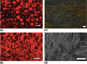
Cadmium selenide (CdSe) has proven to be a model material for understanding inorganic nanocylinder phase behavior because it can be prepared in a variety of sizes (1 < L/D < 15), with nearly monodisperse size distribution.Reference Li, Walda, Manna and Alivisatos10, Reference Baranov, Fiore, van Huis, Giannini, Falqui, Lafont, Zandbergen, Zanella, Cingolani and Manna91 CdSe has potential applications in light emitting diodes, flat panel displays, and electro-optic modulators;Reference Li, Walda, Manna and Alivisatos10 the assembly of liquid crystalline CdSe dispersions onto substrates has been demonstrated.Reference Li and Alivisatos8 The Alivisatos group first reported the liquid crystalline phase formation of 40 nm long, 4 nm diameter CdSe (L/D =10) in cyclohexane in 2002.Reference Li, Walda, Manna and Alivisatos10 As shown in Fig. 5, in the biphasic region the microstructure consisted of birefringent tactoids similar to that observed in lyotropic polymer liquid crystalsReference Donald and Windle37; the red background is the result of the CdSe absorption spectra. At higher concentrations, Schlieren textures characteristic of nematic phase formation emerged. Further confirmation of liquid crystalline phase behavior was obtained using a combination of wide-angle x-ray diffraction (WAXD) and small-angle x-ray scattering (SAXS).Reference Li and Alivisatos8 Based on optical microscopy for CdSe with L = 49 nm, D = 3.8 nm (L/D = 13), even at 88 wt% (~50 vol%) isotropic domains were still present. This further highlights the large mass fractions that can be required to achieve a fully liquid crystalline dispersion.Reference Li, Walda, Manna and Alivisatos10 Later investigations by the same group, using CdSe (L/D = 20) in anhydrous cyclohexane and allowing for two months equilibration time used 2H-NMR to find the volume ratio for the isotropic and liquid crystalline phases and the phase transitions: ϕI ≈ 12 vol% and ϕN ≈ 18 vol%.Reference Li, Marjanska, Park, Pines and Alivisatos9 Similar to the case of SWNTs in superacids, the phase boundaries were found to be only very weakly dependent on temperature in the range of 25–75 °C. The empirical CdSe/anhydrous cyclohexane phase boundaries were compared to theoretical values of 22 and 30 vol% based on Onsager theory or 19 and 22 vol% based on models developed by LeeReference Lee92 and Bolhuis.Reference Bolhuis, Stroobants, Frenkel and Lekkerkerker93 The authors attributed the discrepancy from theory to the attractive interactions between CdSe nanocylinders. The interparticle attraction results in a more positive solute-solvent interaction parameter. This results in mixing being less enthalpically favored and a larger concentration difference between the nanocylinder-rich and solvent-rich phases.Reference Li, Marjanska, Park, Pines and Alivisatos9 In addition to nematic phase formation, CdSe smectic phases have also been reported,Reference Li and Alivisatos8, Reference Talapin, Shevchenko, Murray, Kornowski, Forster and Weller94 but these reports were based on the morphology of solid structures produced by drying the dispersions and not direct characterization of the liquid crystalline phase. It can be difficult to distinguish ordering on substrates resulting from capillary forces, surface forces, and evaporation induced concentration gradients from ordering resulting from dispersion liquid crystallinity. However, smectic phase formation would be facilitated by monodisperse samples and the permanent dipole along CdSe’s long axis.Reference Li and Alivisatos8
Cross polarized optical microscopy. (a) Birefringent CdSe tactoids formed in the biphasic region. (b) CdSe Schlieren textures observed at a later stage of evaporation. (c) Biphasic birefringent spaghetti morphology in silver-ethylene glycol (Ag-EG) dispersion similar to that observed for SWNTs. (d) Schlieren texture in nematic Ag-EG dispersion. Scale bars are 20 μm in all images. (a, b) Reproduced from Li et al.Reference Li, Walda, Manna and Alivisatos10 Copyright 2002 American Chemical Society. (c, d) Modified from Murali et al.Reference Murali, Xu, Marshall, Kayatin, Pizarro, Radhakrishnan, Nepal and Davis90 Copyright 2010 American Chemical Society.

As shown in Fig. 5, the biphasic and nematic microstructures formed by 6.8 μm long 100 nm in diameter (L/D = 68) silver (Ag) nanowires in ethylene glycol (EG) are in stark contrast to the classical microstructure observed for CdSe/cyclohexane. The Ag/EG closely resembles the strand-like microstructure observed in weakly attractive SWNT-superacid liquid crystals (Fig. 3). Since both the (Ag) and (CdSe) nanocylinders have higher persistence length to length ratios (rigidities) than rodlike polymers, this suggests that the contour length may significantly affect the liquid crystal microstructure, particularly in the biphasic region where the majority of the system is isotropic and nematic domains are widely separated. However, since the microstructure of biphasic SWNT-superacid dispersions is affected by solvent quality (Fig. 4) contour length cannot be the sole determinant of microstructure. Developing an understanding of how size and the balance of attractive and repulsive interactions affect microstructure is an important question since the microstructure of the dispersion significantly influences the microstructure of the final solid assembly.Reference Davis, Parra-Vasquez, Green, Rai, Behabtu, Prieto, Booker, Schmidt, Kesselman, Zhou, Fan, Adams, Hauge, Fischer, Cohen, Talmon, Smalley and Pasquali77 Smoother, more defect free, liquid crystalline morphologies lead to smoother more defect free films, fibers and devices with better properties.Reference Davis, Parra-Vasquez, Green, Rai, Behabtu, Prieto, Booker, Schmidt, Kesselman, Zhou, Fan, Adams, Hauge, Fischer, Cohen, Talmon, Smalley and Pasquali77 In addition to having a rarely reported biphasic microstructure, the Ag-EG system is fundamentally interesting because it has significant shape as well as size polydispersity. The dispersion is formed from a dispersion of nanowires and roughly spherical nanoparticle aggregates (<D> ≈ 200 nm). In general, nanoparticles formed during nanowire synthesis are considered as contaminants; there has been significant research on their removal through centrifugation,Reference Sharma, Park and Srinivasarao85, Reference Sharma, Park and Srinivasarao89 filtration, and other methods. However, shape polydispersity can result in depletion effects and facilitate nematic phase formation at reduced concentration.Reference Baranov, Fiore, van Huis, Giannini, Falqui, Lafont, Zandbergen, Zanella, Cingolani and Manna91, Reference Urakami and Imai95 Based on both differential scanning calorimetry studies and the minimum concentration at which no isotropic domains could be observed by cross-polarized optical microscopy, ϕN ≈ 0.4 vol% for the Ag-EG system. This is an order of magnitude lower than the Onsager prediction and can be attributed to depletion effects induced by the nanoparticle aggregates. This suggests that controlled amounts and sizes of nanoparticle “contaminants” can be beneficial by enabling nanocylinder assembly at low volume and mass fraction. From an application viewpoint, the lyotropic Ag dispersions are interesting because of silver’s excellent electrical, optical, thermal, and antimicrobial properties. Aligned assemblies of silver are promising materials for a range of applications including surface-enhanced Raman scattering (SERS) substrates, optoelectronic devices, antimicrobial surfaces, and biomedical devices.Reference Pang, Meng, Fang and Zhang96–Reference De, Higgins, Lyons, Doherty, Nirmalraj, Blau, Boland and Coleman100 Liquid crystalline processing will facilitate development of applications benefited by nanowire alignment since, as observed for other lyotropic systems, coatings and films prepared from biphasic and nematic dispersions have better alignment than those prepared from isotropic dispersions.Reference Ericson, Fan, Peng, Davis, Zhou, Sulpizio, Wang, Booker, Vavro, Guthy, Parra-Vasquez, Kim, Ramesh, Saini, Kittrell, Lavin, Schmidt, Adams, Billups, Pasquali, Hwang, Hauge, Fischer and Smalley23, Reference Donald and Windle37, Reference Murali, Xu, Marshall, Kayatin, Pizarro, Radhakrishnan, Nepal and Davis90, Reference Zamora-Ledezma, Blanc, Maugey, Zakri, Poulin and Anglaret101
In addition to semiconducting and metallic nanocylinders, naturally occurring and synthetic minerals can be assembled into liquid crystalline phases. For example, the liquid crystalline phase behavior of goethite (α-FeOOH) nanorods has been the subject of considerable study. The outstanding research described in Lemaire et al.Reference Lemaire, Davidson, Petermann, Panine, Dozov, Stoenescu and Jolivet54, Reference Lemaire, Davidson, Panine and Jolivet102–Reference Lemaire, Davidson, Ferre, Jamet, Panine, Dozov and Jolivet105 and Vroege et al.Reference Vroege, Thies-Weesie, Petukhov, Lemaire and Davidson86 provide a detailed exploration of goethite phase behavior and the effects of magnetic and electric fields on alignment using a combination of optical microscopy, SAXS, and statistical physical models developed for the orientation distribution function. For goethite with L = 150 ± 25 nm, D = 25 ± 10 nm, and thickness T = 25 ± 5 nm, Lemaire et al.Reference Lemaire, Davidson, Petermann, Panine, Dozov, Stoenescu and Jolivet54 found empirical values of ϕI = 5.5 vol% ϕN = 8.5 vol%. As with many other nanocylinder dispersions, the phase transitions were insensitive to temperature.Reference Lemaire, Davidson, Petermann, Panine, Dozov, Stoenescu and Jolivet54 The predicated values based on the model they developed using an effective diameter to account for electrostatic repulsion were ϕI = 15 vol% and ϕN = 17 vol%. The authors noted that while the observed phase behavior was similar to that expected based on Onsager and related theories, quantitatively predicting the phase boundaries was challenging due to (i) the goethite not being truly cylindrical, (ii) low aspect ratio compared to the Onsager assumption of infinite length, (iii) large surface charge, and (iv) polydispersity.Reference Lemaire, Davidson, Petermann, Panine, Dozov, Stoenescu and Jolivet54, Reference Lemaire, Davidson, Ferre, Jamet, Petermann, Panine, Dozov and Jolivet104 Subsequent work on goethite revealed that the phase behavior was surprisingly rich and nematic, smectic, and columnar phases could coexist in a single dispersion of highly polydisperse rods (L = 216 nm ± 55%, D = 35 nm ± 48%, and T = 16 nm). This result is contrary to the general belief that highly polydisperse systems are incapable of smectic phase formation. Above 10 vol%, suspensions stored in a vertical capillary tube separated into a top nematic layer displaying Schileren patterns, a middle smectic layer displaying Bragg reflections, and a bottom columnar layer without any unique optical characteristics. The structure of each phase was confirmed using SAXS. The authors attributed their surprising result to the coupling of sedimentation and length fractionationReference Vroege, Thies-Weesie, Petukhov, Lemaire and Davidson86 and highlight that polydispersity can actually be useful in the formation of aligned phases from nanocylinder dispersions.
V. CELLULOSE NANORODS
The characterization of cellulose fibers on the nanometer level began in the mid 1950s, and there were a number of investigations into cellulose nanocylinder phase behavior by the 1990s. However, cellulose nanocylinders have only recently been considered as a nanoscale building block for advanced materials.Reference Kim, Bae and Lim106–Reference Samir, Alloin and Dufresne113 The current interest in cellulose is the result of several factors. First, like SWNTs, cellulose nanorods are a strong low density material. With a bending strength of 10 GPa and Young’s modulus of 150 GPa, their mechanical properties are within an order of magnitude of those of carbon nanotubes.Reference Podsiadlo, Choi, Shim, Lee, Cuddihy and Kotov110 In addition, cellulose is one of the world’s most naturally abundant materials and different size cellulose nanocylinders can be isolated from different raw materials including cotton,Reference Podsiadlo, Choi, Shim, Lee, Cuddihy and Kotov110, Reference Revol, Godbout, Dong, Gray, Chanzy and Maret114 wood,Reference Bondeson, Mathew and Oksman115–Reference Revol, Bradford, Giasson, Marchessault and Gray117 and tunicateReference Azizi Samir, Alloin, Sanchez and Dufresne118, Reference Favier, Canova, Cavaille, Chanzy, Dufresne and Gauthier119 (Table I). Finally, their tailorable surface chemistry facilitates easier dispersion and processability than carbon nanotubes.
Cellulose nanocylinder size and shape obtained from different raw materials. Reproduced from Beck-Candanedo et al.Reference Beck-Candanedo, Roman and Gray116 Copyright 2005 American Chemical Society.

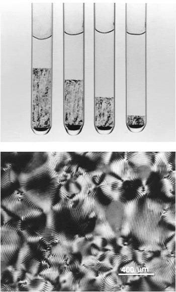
From a theoretical viewpoint, aqueous suspensions of acid hydrolyzed cellulose nanorods are model systems for studying the liquid crystalline phase behavior of cylindrical ionic species.Reference Orts, Godbout, Marchessault and Revol120 Many polymer and cellulose nanocylinder liquid crystal researchers use low magnification imaging of cuvettes to determine the phase boundaries. Both the sample transparency and large domain sizes make this a feasible approach that is far simpler than high magnification optical microscopy over a range of concentrations. It should be noted, however, that the images in the literature vary significantly in appearance depending on whether normal light, parallel polarizers, or cross polarizers were used. In addition, it can be difficult to determine whether differences in appearance at the bottom of the sample, such as the solid black region shown in Fig. 6, are due to undispersed sediment or to optical artifacts. Nonetheless, extrapolating plots of the volume fraction of the anisotropic phase versus the total nanocylinder concentration provides a consistent and simple method for estimating ϕI and ϕN.
(Top) Phase separation of aqueous cellulose nanocylinder suspension, the bottom birefringent region decreases with decreasing concentration. From left to right the concentrations are 8.78, 7.75, 6.85, and 5.78 wt%. (Bottom) Cholesteric fingerprint texture liquid crystalline cellulose dispersion. Reproduced from Dong et al.Reference Dong, Kimura, Revol and Gray42 Copyright 1996 American Chemical Society.

Based on optical imaging of cuvettes [Fig. 6(a)] and confirmation of cholesteric fingerprint textures [Fig. 6(b)], Dong et al.Reference Dong, Kimura, Revol and Gray42 thoroughly analyzed the phase behavior of aqueous dispersions of cellulose nanocylinders 70–170 nm long and ~7 nm in diameter as a function of ionic strength. They found that at weight fractions below 4.6% the sample was completely isotropic, and above 13.1% it was completely liquid crystalline. Contrary to the expectation for monodisperse hard rods, the concentrations in the isotropic and anisotropic phases were a function of the total rod concentration. This was attributed not only to polydispersity but also to the change in ionic strength in the aqueous medium resulting from changing the concentration of charged cellulose nanocylinders. As the concentration of polyions introduced by the cellulose increased, the ionic strength increased, and the effective diameter of the rods decreased. In contrast, for experiments in which the ionic strength was held constant, the concentration in each phase was independent of the total rod concentration. These results highlight the importance of considering not only physical polydispersity, but the effects of electrostatic interactions and effective diameter on the phase behavior of nanocylinder dispersions. The authors also showed that both the phase boundaries and the cholesteric pitch were very sensitive to the addition of electrolytes to the dispersions. The cholesteric pitch P is often considered to be an indicator of the interaction between particles; smaller pitch is considered indicative of stronger interactions.Reference Dong, Kimura, Revol and Gray42 Both the fraction of the anisotropic phase and its pitch decreased significantly with increasing electrolyte concentration in biphasic samples. This is similar to polyelectric polymer dispersions in which the average interparticle distance in the anisotropic phase of a biphasic system will decrease upon salt addition.Reference Orts, Godbout, Marchessault and Revol120
It is noteworthy that the experimental results in Dong et al.Reference Dong, Kimura, Revol and Gray42 were found to generally be in good agreement with the Stroobants, Lekkerker, and Odijk (SLO) modified Onsager theory,Reference Stroobants, Lekkerkerker and Odijk121 which considers an increase in effective diameter and a twisting factor due to electrostatic repulsion. Subsequent work by the same authors explored the volume fraction of the anisotropic phase as a function of total cellulose nanocylinder concentration in the presence of a variety of inorganic and organic counterions.Reference Dong and Gray122 They found that for inorganic counterions, the volume fraction required for anisotropic phase formation increased in the order H+ < Na+ < K+ < Cs+. For organic counterions, this critical concentration generally increased with counterion size, indicating that the phase equilibrium was the result of the balance between steric repulsion and hydrophobic attraction. Interestingly, the authors also found that both the phase boundaries and pitch were less sensitive to temperature than polymeric cholesteric phases and attributed this behavior to the only slight temperature dependence of ionic and steric interactions.Reference Dong and Gray122
Cellulose nanorod phase behavior is, however, sensitive to depletion interactions. Several studies such as those by Beck-Candanedo et al.Reference Beck-Candanedo, Viet and Gray123, Reference Beck-Candanedo, Viet and Gray124 have investigated the effects of ionic dyes on dispersion phase behavior. Anionic dyes were found to induce phase separation at lower ionic strengths than simple electrolytes such as NaCl. This is most likely due to the dyes’ polyvalency and larger hydration radius. However, cationic dyes, which are electrostatically attracted to cellulose, and those which bind to cellulose, were found not to induce phase separation.Reference Beck-Candanedo, Viet and Gray123 This finding is reminiscent of the finding that DNA, which strongly adsorbs onto carbon nanotubes, does not cause depletion attraction, but HLA and synthetic surfactants which are less strongly interacting can induce depletion effects. However, as described in Beck-Candendo et al.,Reference Beck-Candanedo, Viet and Gray123 depletion attraction is also dependent on the size of the additive relative to the inter-rod spacing. For example, in suspensions where the cellulose nanocylinder spacing was estimated to be 20 nm, the addition of dextran dyes whose radius of gyration was similar to the cellulose spacing did not induce phase separation while larger dyes did induce phase separation. Furthermore, the authors found that the relative charge of the dye and the cellulose nanocylinder also contributed to whether or not phase separation occurred.
As for other liquid crystals, the application of shear or magnetic fields should affect the alignment of cellulose nanocylinder liquid crystals. SANS studies of shear and magnetic induced alignment by Orts et al.Reference Orts, Godbout, Marchessault and Revol120 were used to investigate changes in order parameter and showed that cholesteric ordering is disrupted by shear in favor of nematic ordering with the long axis being aligned in the direction of flow.Reference Orts, Godbout, Marchessault and Revol120 However, recent work by Pan et al. showed retention of the chiral pitch in films dried in the presence of a magnetic field.Reference Pan, Hamad and Straus125 Controlling the chiral pitch in the dispersion can therefore result in films with controllable optical properties. If the pitch is on the same length scale as the wavelength of visible light, the films can be used as an interference device that reflects circularly polarized light in a specific wavelength range.Reference Orts, Godbout, Marchessault and Revol120 The perceived color of the films with cholesteric order will depend on the pitch and the angle of the incident light. One of the interesting applications for cholesteric films that have been proposed is optically variable films for security papers.Reference Pan, Hamad and Straus125 However, more studies are needed to explore the effects of magnetic and shear fields on dispersion microstructure and the microstructure of bulk materials assembled from the dispersions.
VI. CONCLUSION
Liquid crystalline assembly of nanocylinders is an exciting addition to the long established field of liquid crystalline science and a promising route for producing aligned materials composed of nanocylinder building blocks. While decades of research on lyotropic polymer liquid crystals have resulted in significant theoretical understanding and practical applications, understanding of nanocylinder liquid crystals is generally at a much earlier stage. To date, most experimental researchers have focused on only one of these exciting new systems, but comparing results from different systems highlights common findings such as the limited ability to use temperature to tune phase behavior. There are several key challenges for future nanocylinder liquid crystal research. First, standard protocols for identifying nanocylinder liquid crystalline phase behavior need to be established. While not all of the possible methods will work for all systems, more consistent quantification of both ϕI and ϕN is needed to enable direct comparison between systems. Second, since carbon nanotube, inorganic nanocylinder, and cellulose nanorod phase behavior have all shown little temperature dependence, more investigation of the factors controlling nanocylinder liquid crystal phase behavior is needed. Third, there is a need to better understand what controls microstructure, particularly in the biphasic region, and to discover how to control the final microstructure (e.g., alignment or pitch) in the final assembled products. Similarly, there is a need for increased understanding of the effects of shear, magnetic fields, and electric fields on microstructure and stability. Finally, in parallel to the experimental work, there is a need for ongoing development and acceptance of a theoretical framework that can be adapted for the wide range of sizes, polydispersities, van der Waals attractions, electrostatic repulsions, and depletion interactions. Viewing these challenges and the field of nanocylinder liquid crystals from a common perspective will help accelerate achievement of these goals. This will enable the impact of 21st century nanocylinder liquid crystals to rival that of 20th century rodlike polymer liquid crystals.
ACKNOWLEDGMENTS
This work was supported by the National Science Foundation under CAREER grant NSF-CMMI-0846629 and Fluid Dynamics Grant CBET-0854010.