Introduction
In recent years, the use of fossil fuels has caused serious environmental problems and human health threatens. A promising solution is to develop renewable energy technology to shift society to renewable energy sources.[ Reference Su and Vayssieres 1 ] Nevertheless, the renewable energy has disadvantages such as the discontinuous of time and space, low-energy density, and difficulty to be integrated into online power network. So there is a necessity to develop a device to improve the quality and reliability of renewable energy. Furthermore, in the field of electrical car industry, a new battery different from the traditional one for stable and efficient energy storage is also needed. Supercapacitor emerged as a good candidate because of its high-energy density, high-power density, superior charge and discharge rates, and infinite recycle times theoretically.[ Reference Gallo, Simões-Moreira, Costa, Santos and dos Santos 2 ]
There are three major types of electrode for supercapacitor, which are carbon electrode, metal oxide electrode, and conducting polymer electrode.[ Reference Wang, Zhang and Zhang 3 ] Carbon electrode has the advantages of high specific surface area and good conductivity. Carbon-based materials such as activated carbon,[ Reference Gamby, Taberna, Simon, Fauvarque and Chesneau 4 ] mesoporous carbon,[ Reference Lin, Chen, Liu, Yang, Bi, Xu and Huang 5 ] carbon nanofibers,[ Reference Kim, Wee, Kim, Yang and Yang 6 ] and graphene[ Reference Shao, El-Kady, Wang, Zhang, Li, Wang, Mousavi and Kaner 7 ] are often used. The metal oxide electrode has the feature of good electrochemical performance, which attracts the researchers' interest.[ Reference Zeng, Yu, Meng, Fang, Lu and Tong 8 ] The third type, conducting polymer electrode possesses good electronic conductivity, small resistance, and high specific capacity.[ Reference Xia, Chen, Wang, Hedhili, Wei and Alshareef 9 ] Among them, metal oxide received much attention due to its high thermal stability, abundance, and low manufacturing cost.[ Reference Jiang, Li, Liu, Huang, Yuan and Lou 10 ] Yang et al.[ Reference Yang, Ding, Lin, Chen, Li, Qiang, Ebrahimi, Mai, Wong and Wang 11 ] reported a new supercapacitor using MnO2 and Fe2O3 as electrode. Deng et al.[ Reference Deng, Kang, Bai, Li, Li, Liu, Yang, Gao and Liang 12 ] synthesized a novel supercapacitor using the Co3O4 particle prepared by citric acid and cobalt (II) nitrate hexahydrate, whose capacitance reached 362.8 F/g. Fe2O3 is regarded as a promising candidate for anode material, which possesses a suitable voltage window and high theoretical specific capacitance in negative potential. It also has the advantage of low-cost, ready availability, environmentally sound, and resistance to corrosion.[ Reference Binitha, Soumya, Madhavan, Praveen, Balakrishnan, Subramanian, Reddy, Nair, Nair and Sivakumar 13 ] Shivakumara et al.[ Reference Shivakumara, Penki and Munichandraiah 14 ] reported a high specific surface area Fe2O3 and the capacitance density reached 300 F/g at the current density of 1 A/g. Lorkit et al.[ Reference Lorkit, Panapoy and Ksapabutr 15 ] reported Fe2O3-based supercapacitor with the capacitance density of 532.8 F/g deposited by a sol–gel method. For typical metal oxide pseudocapacitive electrode, the high electrical resistance usually leads to poor rate capability and poor cyclic stability for the long-term charge–discharge operation. This instability can be owed to their relatively poor structural stability, overoxidative decomposition, or active materials loss. To address this problem, the metal oxides are combined with conductive carbon materials to enhance the rate capability and cycling performance.[ Reference Zhi, Xiang, Li, Li and Wu 16 ]
For example, Liao et al.[ Reference Liao, Li, Jin, Yang and Wang 17 ] deposited Co3O4 on the carbon nanolayer showing a significant capacitance density of 3480 F/g. Gu et al.[ Reference Gu, Lou, Li, Chen, Ma and Shen 18 ] reported a hybrid nanostructures of reduced graphene oxide/Fe2O3 hollow nanospheres which exhibits a high specific capacitance of 11.57 F/cm3 at a scan rate of 200 mV/s. Fe2O3 NDs@NG-0.75 sample capable of delivering a high specific capacitance of 274 F/g at 1 A/g and displays superior capacitance retention after 100,000 cycles (about 75.3% at 5 A/g) was reported by Liu et al.[ Reference Liu, Lang, Zhang, Hu and Yan 19 ] It was also observed by Huang that a positive synergetic effect between N-rGO and α-Fe2O3 significantly improved the capacitance, rate capability, and cycle life of their hybrid supercapacitor (268.4 F/g at 2.0 A/g, deterioration of 4.21% after 2000 cycle at 3.0 A/g).[ Reference Liu, Zhang, Xu, Huang, Tan and Mai 20 ]
In our research, C/Fe2O3 composite electrodes were deposited using a facial one-step method. This structure showed promising performance when utilized as a supercapacitor anode. The influences of C/Fe ratio in the composite, annealing temperature, annealing time, and heating rate on the capacitance performance were investigated. The optimized C/Fe2O3 supercapacitor gave a capacitance density of 85.3 F/g at a current density of 5 A/g. As cobalt oxide was reported to be promising electrode material for supercapacitor as its high redox activity and great reversibility,[ Reference Liu, Pell and Conway 21 ] Co3O4 was further added into the C/Fe2O3 composite and the influences of different amount of cobalt on the structural and electrochemical performance of C/Fe2O3 were investigated. It was found that the capacitance was further increased to a value as high as 144.4 F/g at a current density of 5 A/g. This low-cost displayed a great potential as promising large-scale method for supercapacitor electrode material fabrication. The strategy of further decorating metal oxides on a hybrid structures can also be extended to other pseudocapacitive materials for the next-generation energy storage devices.
Experimental details
Synthesis of C/Fe2O3 hybrid composite
The chemical reagents used, including Fe(NO3)3·9H2O, Co(NO3)2·6H2O, and glucose powder were purchased from Sinopharm Chemical Reagent co., Ltd., China. All the chemical reagents are analytical grade and used as received. C/Fe2O3 hybrid composite was deposited on fluorine-doped tin oxide (FTO) glass by a facial method of spin-coating and annealing approach. In a typical synthesis, a 40 mL precursor solution was prepared by dissolving 8 g glucose and 4 g Fe(NO3)3·9H2O in an ultrasonic cleaner for 20 min. The solution was then refluxed in an oil bath at 125 °C for 50 min with stirring at the speed of 600 rpm. During the reflux reaction, colloid solution containing Fe2O3 nanoparticles can be obtained. The obtained precursor solution was then spincoated on the FTO glass at 2000 rpm for 20 s. This process was repeated for three circle using 0.5 mL precursor for each circle. During each circle the FTO glass was heated on the heating plate for 20 min at 80 °C. The obtained film was then annealed in N2 atmosphere in a rapid heating furnace at a certain temperature for a certain time. The C/Fe2O3 ratio was controlled by adjusting the amount of the glucose and ferric nitrate dissolved in the precursor solution. For synthesis of C/Fe2O3/Co3O4 sample, Co(NO3)2·6H2O was dissolved in the precursor solution along with Fe(NO3)3·9H2O, and glucose powder at the first step and keep other procedures unchanged.
Structural characterization
Scanning electron microscopy (SEM, JSM7800F, JEOL, Japan) and transmission electron microscopy (TEM, G2F30, FEI, USA) were employed to verify the morphology and structure of C/Fe2O3 electrode.
An x-ray photoelectron spectrometer (XPS, AXIS Ultra DLD, Shimadzu/Kratos Analytical, Japan) was performed to determine the chemical components. XRD patterns were collected on a diffractometer (PANalytical, the Netherlands).
Electrode preparation and electrochemical measurements
To demonstrate its practical application, we employed a simple device architecture consisting of two same C/Fe2O3 electrodes (1 × 1 cm2) that serve as both electrodes and charge collectors.[ Reference Kaempgen, Chan, Ma, Cui and Gruner 22 ] The electrodes were separated by a membrane filter paper (Whatmann #4) wetted with the 8 M KOH electrolyte and packed using a metal clamp. All electrochemical measurements were carried out at room temperature on an electrochemical working station (CHI760D) with two a two-electrode system. The specific capacitance in the two-electrode system is calculated by C = IΔt/(mΔU), and areal capacitance is calculated by C a = It/(ΔUS), where I is the discharge current, Δt is the discharge time, ΔU is the voltage drop upon discharging, m is the individual electrode mass including the working electrode and counter electrode, and S is the geometrical area of the electrode. The influence of C/Fe2O3 ratio, annealing time, annealing temperature, and heating rate on the electrochemical properties of C/Fe2O3 electrode were studied by calculating the specific capacitance of the obtained device.
Results and discussion
Morphology and structural characterization
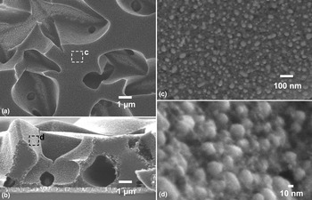
The structural and morphological properties of the obtained C/Fe2O3 composite were characterized by SEM and TEM. SEM image shown in Fig. 1 indicates that the surface of C/Fe2O3 composite is unsmooth with large micro-size pores throughout the film. A possible explanation is that the fast temperature increase rate and decomposition of glucose during the annealing procedure induced these pores. A close look into the surface of the top layer and inner wall of pores indicated that C/Fe2O3 is the binding of ~30 nm Fe2O3 nanoparticles by filamentous carbon.
SEM images of C/Fe2O3 electrode for supercapacitor.

To study the behavior of pore evolution during the heat treatment, we prepared C/Fe2O3 electrode with different heating rates and their surface topography characterized by SEM were shown in Fig. S1, in which we can see that smaller heating rate leads to less pores and a smoother surface. With a smaller heating rate, the decomposition rate of glucose is also smaller due to a slower release of gas product. C/Fe2O3 electrode of the different heating rate is prepared shown in Fig. S2. From the I–V curves, we can see that when the heating time is 10 min, the I–V curve is gentle and has the largest area. The optimum heating rate is 55 °C/min. Besides the heating rate, we also studied the influence of annealing time on its morphological property and the result is shown in Fig. S3. It can be seen that the particle size increases as the heating time for precursor increases, and a longer annealing time leads to octahedral Fe2O3 crystals with size range from 15 to 75 nm. C/Fe2O3 electrodes of the different annealing time at 550 °C were also prepared, whose I–V curves are shown in Fig. S4. From the I–V curve, we can see that when the annealing time is 10 min, the I–V curve is gentle and has the largest area, which means the 10 min annealing time is the optimum condition. The effect of annealing temperature on the morphology and performance of C/Fe2O3 electrodes were also investigated. From Fig. S5, we can see that when the annealing temperature is 550 °C, the I–V curve has the largest area, indicating that the optimum annealing temperature is 550 °C.
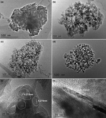
Since the hematite exhibit good pseudocapacitor behavior with a high specific capacitance[ Reference Reddy, Yu, Sow, Shen, Lim, Subba Rao and Chowdari 23 ]; however, its poor electrical conductivity yet limit its performance. The carbon used here facilitates the electron transfer between the active materials (Fe2O3) and the current collector (FTO). The amount ratio between carbon and hematite should have significant influence on the performance. To investigate this influence, the C/Fe2O3 ratio was adjusted by changing the amount of the glucose and ferric nitrate used during the deposition. C/Fe2O3 samples synthesized with weight ratio of C6H12O6 to Fe(NO3)3·9H2O equals 4:1, 2:1, 1:1, and 1:2 are denoted as C/Fe4-1, C/Fe2-1, C/Fe1-1, and C/Fe1-2, respectively. The morphology properties of the as-prepared C/Fe2O3 composites were characterized by TEM as shown in Fig. 2. It was found that Fe2O3 nanoparticles with 5–10 nm in size are well encapsulated in carbon nanosheet matrix. With increase of glucose to ferric nitrate weight ratio, more Fe2O3 nanoparticles and thinner carbon nanosheet were observed. The high-resolution TEM (HRTEM) images of sample with glucose and ferric nitrate weight ratio of 1:1 clearly demonstrate the crystallized Fe2O3 nanoparticles [Fig. 2(e)] and the carbon nanosheet [Fig. 2(f)]. The lattice fringes with a distance of 0.275 nm were clearly observed, which can be indexed as the (104) plane of α-Fe2O3 (JCPDS 00-003-0800). The HR-TEM micrograph in Fig. 2(f) shows a typical carbon nanosheet with clear parallel fringes of 0.332 nm, which can be indexed to the (002) spacing of graphite. This image also indicated that the obtained nanosheets are several graphene layers thick.
TEM images of C/Fe2O3 samples synthesized with different C6H12O6: Fe(NO3)3·9H2O weight ratios: (a) C/Fe4-1, (b) C/Fe2-1, (c) C/Fe1-1, (d) C/Fe1-2. HRTEM of Fe2O3 particles (e) and carbon nanosheets (f) of sample C/Fe1-1.

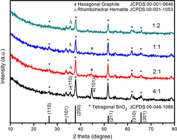
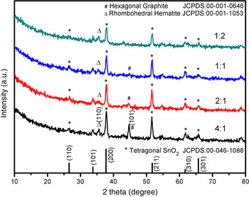
The XRD analysis is shown in Fig. 3. However, most of the observed peaks are attributed to the FTO substrate (marked with *, Tetragonal SnO2 JCPDS:00-046-1088). A low peak at 35.7°, which can be attributed to the (110) plane of Rhombohedral hematite (marked with Δ, JCPDS:00-001-1053), was observed. Another peak observed at 44.6° can be denoted as the (101) plane of Hexagonal Graphite (marked with #, JCPDS:00-001-0646). The diffraction peaks of Fe2O3 were relatively weak, which suggested that the obtained Fe2O3 particles are disordered with a low degree of graphitization which could be due to exist of carbon that hinders the recrystallization of Fe2O3.
XRD pattern of C/Fe2O3 electrode synthesized with different C6H12O6: Fe(NO3)3·9H2O weight ratios (1:2, 1:1, 2:1, and 4:1).
The chemical bonding states in the C/Fe2O3 samples synthesized with different glucose to ferric nitrate weight ratio were further analyzed by XPS measurements, as shown in the Supporting Information (SI), Fig. S6. Three elements (Fe, O, and C) were observed on the surface of the products. The Fe 2p XPS spectra of the sample exhibit two peaks at 724.6 and 711.0 eV, which can be attributed to the Fe 2p1/2 and Fe 2p3/2 peaks, respectively. A weak satellite peak at 722.6 eV was observed for all three samples, confirming the formation of Fe2O3 other than mixed oxide of Fe(II) and Fe(III) (Fe3O4).[ Reference Zhu, Zhu, Murali, Stoller and Ruoff 24 ] Two peaks in the O 1s spectra were observed at 530.4 and 532.0 eV corresponds to the oxygen species in the metal oxide and residual hydroxyl/carbonate species (e.g., C–O–C and –COOH) bonded with C atoms in grapheme.[ Reference Balbuena, Carraro, Cruz, Gasparotto, Maccato, Pastor, Sada, Barreca and Sánchez 25 ]
For the C 1s spectra, there are also two peaks observed. The C 1s peaks at 286.2 and 284.8 eV are attributed to carbon from glucose decomposition and carbon contamination (adventitious carbon), respectively.
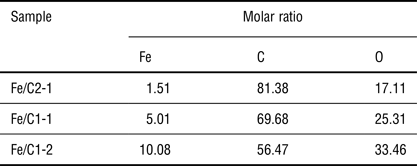
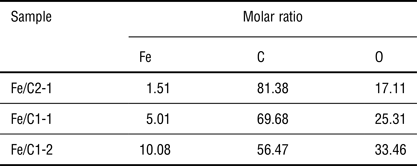
As clearly shown in Fig. S6, the intensities of the Fe 2p peaks increased and the C 1s peaks decreased with decreasing glucose to ferric nitrate weight ratio during the synthesis. The molar ratios of the elements in C/Fe2O3 samples were calculated and shown in Table I. The ratio of Fe2O3 to carbon can be well controlled by adjusting the glucose to ferric nitrate weight ratio during the synthesis.
Molar ratio of elements in C/Fe2O3 determined by XPS.
Electrochemical characterizations
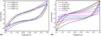
Cyclic voltammetry (CV) and galvanostatic charge–discharge measurements were examined with two electrode mode to evaluate the electrochemical properties of the C/Fe2O3 composites. The CV curves show a quasi-rectangular shape and the area of I–V curve can determine the performance of capacitor. A larger area of the I–V curve stands for a larger capacitance density. Figure 4(a) shows the representative CV curves of the Fe2O3–grapheme composites with different C/Fe2O3 ratios in 8 M KOH electrolyte with a potential window between −1.4 and 0 V (versus counter electrode). From the I–V curve, we can see that the curve for sample C/Fe1-1 possesses the largest area, indicating the best capacitive performance. I–V curves for sample C/Fe1-1 at different scanning rates were also recorded and shown in Fig. 4(b). From the I–V curve, it can see that the peak current increases with increasing scan rate from 0.01 to 0.1 V/s. Moreover, no obvious shape change can be observed among the I–V curves at different scanning rates, indicating a small equivalent series resistance and weak polarization of the electrode.[ Reference Zhu, Murali, Stoller, Ganesh, Cai, Ferreira, Pirkle, Wallace, Cychosz and Thommes 26 ]
(a) I–V curves of different C/Fe2O3 electrodes (0.1 V/s) with different C/Fe ratios: C/Fe4-1, C/Fe2-1, C/Fe1-1, and C/Fe1-2. (b) I–V curves of sample C/Fe1-1 at different scanning rates.

In addition, galvanostatic charge–discharge behaviors for samples with different C/Fe2O3 ratios in 8 M KOH electrolyte were also tested at a current density of 1 mA/cm2. The voltage drop at the beginning of each discharge can be used to evaluate the internal resistances. As shown in Fig. S7, for sample C/Fe1-1, the iR drop is 2.619 V and the resistance is calculated to be 523.8 Ω/cm2. The specific capacitances were calculated from the galvanostatic discharge curves using the equation described in the experimental section. The capacitance density for sample C/Fe1-1 was calculated to be 85.3 F/g.
To develop high-performance electrochemical redox supercapacitors, combination of different redox reactions could induce a synergistic electrochemical interaction and improve the electrochemical performance. For example, synergistic behaviors were found in Cu–Fe oxide system,[ Reference Li, Li, Sun and Li 27 ] V2O5/α-Fe2O3 composite,[ Reference Nie, Lu, Lei, Jiang and Wang 28 ] and NiO/MnO2 core/shell nanocomposites.[ Reference Zhang, Li, Sun, He, Zou, Hu and Chen 29 ]
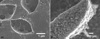
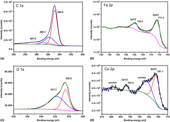
Cobalt is recognized as a promising candidate for electrochemical capacitors due to its highly reversible redox reaction.[ Reference Liu, Pell and Conway 21 ] To further improve the performance of C/Fe2O3 electrode for supercapacitor, cobalt was incorporated into the C/Fe2O3 system by directly adding cobalt source at the spincoating precursor. The C/Fe2O3/Co ratio was adjusted by changing the amount of the glucose, ferric nitrate, and cobalt nitrate used during the deposition. C/Fe2O3/Co samples synthesized with weight ratio of C6H12O6: Fe(NO3)3·9H2O:Co(NO3)2·6H2O equals 8:4:1, 4:2:1, 2:1:1, and 2:1:2 are denoted as C/Fe/Co8-4-1, C/Fe/Co4-2-1, C/Fe/Co2-1-1, and C/Fe/Co2-1-2, respectively. Figure 5 shows the SEM images of sample C/Fe/Co4-2-1. The C/Fe2O3/Co3O4 composite show a similar morphology as the C/Fe2O3 composite that shown in Fig. 1. In addition to the Fe2O3 nanoparticles and filamentous carbon, irregular-shaped particles connecting the sphere Fe2O3 nanoparticles were also found in the composite film. These irregular-shaped particles could be Co3O4 particles. As shown in Fig. 6, XPS measurements were also conducted to check the chemical states and confirm the incorporation of Co3O4. Similar to that of C/Fe2O3 sample (Fig. S6), The O 1s spectrum also can be deconvoluted into two peaks positioned at 530.5 and 531.7 eV, as expected for the oxygen species in the metal oxide and residual hydroxyl/carbonate species.[ Reference Armelao, Barreca, Bottaro, Gasparotto, Maragno and Tondello 30 ] The binding energies of are located at 781.1 and 797.0 eV are attributed to spin–orbit splitting of the Co 2p3/2 and Co 2p1/2,[ Reference Wang, Chen, Gao, Zheng, Zhang and Qian 31 ] respectively, which are characteristics of Co3O4.[ Reference Jimenez, Fernandez, Espinos and González-Elipe 32 ]
(a) Top view and (b) detailed view SEM images for sample C/Fe/Co4-2-1.

XPS spectra of (a) C 1s, (b) Fe 2p, (c) O 1s, and (d) Co 2p for sample C/Fe/Co4-2-1.

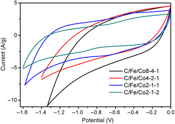
To investigate the electrochemical properties of the composite, the CV and galvanostatic charge/discharge (GCD) tests are carried out. Figure 7 shows the CV curves of C/Fe2O3/Co3O4 samples with different Co contents. As shown in Fig. 7, better quasi-rectangular shape CV curves were observed compared with that of C/Fe2O3 samples (Fig. 4), which indicates the good capacitive behavior of the C/Fe2O3/Co3O4 composite electrode materials. The improvement of capacitance of C/Fe2O3/Co3O4 sample should be attributed to the coupling of pseudocapacitance of Co3O4 and Fe2O3 nanoparticles. Moreover, the sample C/Fe/Co2-1-1 possesses the largest area, indicating an optimal Fe/Co weight ratio. The GCD measurements of C/Fe2O3/Co3O4 composites are shown in Fig. S8. Triangular-shaped curves with iR drops of 0.3–0.4 V were observed. These iR drops are much smaller than C/Fe2O3 samples and much smaller corresponding resistances of electrode. The specific capacitance of the optimal sample C/Fe/Co2-1-1 was calculated to be 144.4 F/g at the current density of 5 A/g.
The CV curve of C/Fe2O3/Co3O4 electrode synthesized with different weight ratios of C6H12O6 : Fe(NO3)3·9H2O: Co(NO3)2·6H2O.

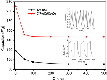
Since the long-term cycling stability is a critical parameter for practical application of supercapacitors. The cycling stability tests for the optimal C/Fe2O3 (C/Fe1-1) and C/Fe2O3/Co3O4 (C/Fe/Co2-1-1) supercapacitors were performed and compared. As shown in Fig. 8, relatively good cycling stabilities were obtained in 500 cycles. Both samples showed a capacity loss within the first 100 recycles and remain stable afterwards. The capacitance density of C/Fe2O3 remained 77% of the initial one and that of C/Fe2O3/Co3O4 remained 68%.
Cycling life tests for C/Fe2O3 and C/Fe2O3/Co3O4 electrode for supercapacitor. Black line is for sample C/Fe1-1, Red line is for sample C/Fe/Co2-1-1.

Conclusions
In summary, we prepared C/Fe2O3 composite electrode as supercapacitor material in a new method-spin coating and annealing. The C/Fe2O3 ratio, heating rate, annealing temperature, and annealing time were optimized to achieve high electrochemical performance. Under the optimum condition (C/Fe1-1 synthesized with glucose to ferric nitrate weight ratio of 1:1, heating rate is 55 °C/min, annealing temperature is 550 °C and annealing time is 10 min), we get the capacitance density of C/Fe2O3 electrode is 85.3 F/g. The addition of cobalt into C/Fe2O3 further improved its capacitance density to 144.4 F/g. XPS confirmed the cobalt composite exists as Co3O4. The optimal cobalt amount is the sample C/Fe/Co2-1-1 synthesized with weight ratios of glucose, ferric nitrate, and cobalt nitrate equals 2:1:1. The C/Fe1-1 and C/Fe/Co2-1-1 samples exhibit good performance, including high capacitance density and good cycling stability for application of low-cost supercapacitor.
Supplementary material
The supplementary material for this article can be found at https://doi.org/10.1557/mrc.2016.60.
Acknowledgments
This work was supported by the National Natural Science Foundation of China (grant numbers 51202186 and 51236007).