I. INTRODUCTION
In the literature many algorithms have been reported on the detection of objects against various types of background [Reference Gregers Hansen1, Reference Rohling2]. In fielded applications, the robustness against deviations of real-life conditions from assumed theoretical models underlying the various available ones, on the one hand, and the cost of implementation, on the other, motivate which algorithm to select. Considering both the sophistication of the algorithms and the computational power of the platforms used in the products, we observe an evolution. Today's radars tend to have a higher bandwidth and higher dynamic range, thereby observing the background with more detail. Lessons learned from fielded systems include that in automated systems the process of detecting objects based on just signal-to-noise ratio does not deliver a balance between detection and false alarm rate that satisfies the operational user. Solutions to restore this balance depend on the parameters of the radar involved, on the clutter background, and on the types of targets [Reference Löhr and Schrodi3, Reference van Genderen4]. Therefore they tend to be non-generic and hence tailoring them to actual requirements is necessary.
The current paper starts from an approach where a multi-staged detection process delivers an initial detection, here referenced as a primitive detection. See also [Reference van Genderen and Kovalenko5]. This primitive detection is supported by a two-dimensional (range–azimuth) region in the coverage of the radar. In the next stage, features are extracted from this support region and finally object detection is based on these features.
The radar as used in the evaluation is a polarimetric radar, measuring the scattering matrix by alternating transmissions in the horizontally and vertically polarized electromagnetic waves in a linear orthogonal polarization basis. The receiver has two orthogonal polarimetric channels operating simultaneously, and therefore all four elements of the scattering matrix are being measured. The radar's range resolution is some 6 m and the beam width is 2°. Since the rotation rate of the antenna is quite high, the time-on-target is very short (approx. 10 ms), leaving insufficient time for Doppler analysis. The scenes evaluated here concern ground-based scenarios.
The paper is organized in the following way. Section II presents some primitive detection methods, based on common constant false alarm rate (CFAR) techniques. Also the proposed multiple stage process of detection and feature extraction is discussed, including the polarimetric detector. Then, Section III presents the evaluation of the process based on both real-life recordings and synthetic objects for non-fluctuating synthetic objects, and Section IV shows the results for a synthetic object with internal fluctuations of the radar cross section (RCS). The paper is concluded with a discussion of the results.
II. MULTI-STAGED OBJECT DETECTOR
Many detectors can be found in the literature. Among the most common is the cell averaging CFAR. This detector assumes a homogeneous background with a known probability density function (pdf); however, this assumption does not apply to the clutter background observed here. In Section III the results of a few of the many different CFAR mechanisms that can be found will be compared. The ones tested here in the first stage of the process are the classical cell averaging CFAR (CA-CFAR), an order statistics CFAR (OS-CFAR), and a CFAR based on a high-resolution cluttermap. All of these detectors are based on signal-to-background ratios only.
Since our radar is polarimetric, one algorithm dealing with the contrast between objects and the clutter background in the polarimetric domain has also been included. The method we have selected is based on the seminal paper by Kelly [Reference Kelly6]. The basic detector proposed in [Reference Kelly6] for radar equipped with N spatially distributed sensors is a generalized likelihood ratio test, leading to the detector

Here z k is the signal as measured in the kth resolution cell,  is the sample covariance matrix of the clutter, and s is a steering vector. H 0,1 is the hypothesis on a signal being absent or present, respectively. The radar in our case does not have an array antenna. In contrast, the four polarimetric channels are regarded as the sensor vector. This implies that the vector s is considered as the polarimetric steering and thus as an exploitation of prior knowledge. In our case this property is used for classification purposes.
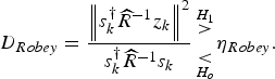
It can be seen that (1) has a linear-quadratic dependency on the measured signal z k. We prefer a linear link between the detector's output and the measured data, for the sake of the robustness of the method. Such a detector was proposed by Robey et al. [Reference Robey, Fuhrmann, Kelly and Nitzberg7]. Its expression is
We have analyzed other detectors as well. Without presenting further details, it is suggested that although some differences exist, the results presented later in this paper are to be generally valid.
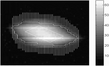
In the second stage of the multi-staged process, features are extracted from those segments of the radar coverage that belong to primitive detections obtained by the various detection mechanisms described above. So, for each of these primitive detections the video that supported this detection was retained, and features were extracted based on this segment. Figure 1 provides a clarification.
Example of an extended object. Shown are the white contour circumscribing the object, the supporting region (vertically hatched), and a diamond representing the size and orientation of the object. The span of the horizontal axis corresponds to 50 m, and the span of the vertical axis corresponds to 180 m.

The following features were extracted from the video:
(a) A contour was extracted circumscribing the object. The video segment was isolated based on the primitive detections, followed by a process from the domain of image processing, i.e. dilation and successively erosion. In the erosion process, a structuring element was selected mimicking the echo of a weak point target, so that basically the segment circumscribed by a contour consists of a number of connected echoes from point objects.
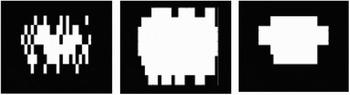
A brief visual explanation of the effect of the dilation/erosion process can be seen from Fig. 2. Figure 2(a) shows the (hypothetical) range–azimuth plane of primitive detections. In the dilation step, each primitive detection is extended in a prescribed way. In our case it is extended to become a 3 × 3 square group of primitive detections. The result is in Fig. 2(b). Then the erosion step includes the fact that the dilated image is convolved with a shape that represents the echo as expected from a weak point source, here resulting in Fig. 2(c).
The length of the contour, expressed in the number of points along the contour, is one of the features to be evaluated.
(b) Given the contour, the shape of the object was evaluated in two different ways:
• By cross-correlating the contour of an object under test with objects observed in previous antenna revolutions, in order to develop a degree of similarity. The contour was treated as a set of complex numbers c(n) = x(n) + jy(n), where x(n) and y(n) are the coordinates in the azimuth and range dimension, respectively, after resampling of the contour. Parameter n is the scan number. This resampling was done so that the number of points of all contours was the same, while for each individual contour the distance between successive points was the same. According to this procedure, the resampled contours were scale-invariant. The degree of similarity was then measured by computing the cyclic cross-correlating the resampled contours of the two objects involved.
Another feature that was retained is the length of the contour, before resampling:
• Higher order moments were computed on the binary image inside the contour. The values of these moments are represented in Fig. 1 by the diamond: the length of its main axis and secondary axis and their orientations. A method that would assess the parameters of an ellipse that best fits the interior of the contour would result in directly related features.
(c) Each resolution cell inside the contour was compared with a set of three basic polarimetric reference objects. These reference objects were a trihedral, a dihedral, and a helix. The output of the Robey test statistic in (2) was developed using the scattering matrices of these detectors as the input for the steering vectors s. The total result then is a vector with three elements, describing the similarity of the object under test with the reference objects. The value of D Robey from (2) should be low for two vectors that are similar. The vector constructed in this way represents the polarimetric features that are used further in this paper.
(d) The total energy inside the contour was measured. For evaluation of the quality of this feature, the normalized standard deviation of the total energy over the sequence of scans was measured.
Example of the result of the dilation/erosion steps. Horizontal: radar sweeps; vertical: range bins. (a) The original range–azimuth plane with primitive detections. (b) The same plane as in (a), but with dilated primitive detections. (c) The same plane as in (b), however after the erosion process.

In the third and final stage, the features of the object under test were compared with the features of objects that were detected previously in order to find whether any similarity could be found. The algorithm used for this comparison was based on the Bayes rule, though with the diagonalized covariance matrix. In this method some prior information must be used to dimension the conditional pdf's of the features, given the class of objects:

Here P(C k|Z k) is the posterior probability on class C k given all measurements Z k until now.
III. EVALUATION OF THE FEATURES
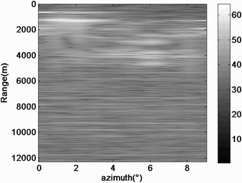
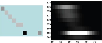
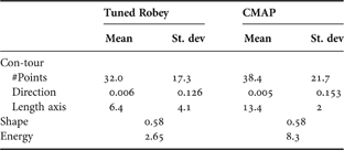
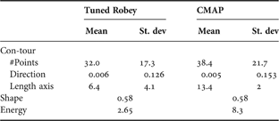
The features described in Section II were evaluated using a clutter background recorded by the polarimetric radar. A diagram showing an image of the total received power in one antenna revolution is given in Fig. 3 on a logarithmic intensity scale. The artificial target was coherently superimposed on the background video. Its geometry is schematically drafted in Fig. 4(a), while Fig. 4(b) shows the video “stamp”. The target moved from the position at [range = 600 m, azimuth = 3°] in a straight line to [range = 3600 m, azimuth = 6°]. Thus its ground truth is exactly known. It has been used for assessing the position accuracy. The average signal-to-clutter ratio in this area is of the order of +7 dB. However, the clutter is very spiky. The signal-to-clutter ratio with respect to the higher discretes in the same area is of the order of −35 dB. The results are summarized in Table 1 for the target as described above. The table provides the measured numbers for five scenarios, i.e. a classical CA-CFAR detector operating in a background of thermal noise and four different detection mechanisms operating in a clutter background. The case for the noise may serve as reference for the best achievable values for the given target. The various candidate methods for primitive detection were implemented and the features as listed in Section II were extracted.
The natural scene used in the evaluation. The intensity is in dB w.r.t. thermal noise.

(a) Schematic layout of the artificial target. The polarimetric scattering matrix is varying. Gray level corresponds to RCS. (b) Radar video of the target. The layout is as in (a). Linear intensity scale.

Overview of the properties of the collected features.

Some observations can be made from this table:
1) The primitive detection based on the tuned Robey detector cluttermap performs best as far as detection alone is concerned. However, the features extracted from the corresponding contours are not very accurate. Also it should be recalled that prior information has been used. If this was not the case, the probability of detection would have been lower.
2) The cluttermap-based detection (CMAP) is second best with a lower detection rate and a better quality of the features.
3) CA-CFAR and OS-CFAR suffer from higher detection loss and less good quality of the features.
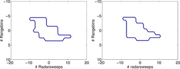
4) Concerning the polarimetric detector it was already commented that it needs a steering vector based on the scattering matrix of the sought object. The lower quality of its features compared to the CMAP detector is probably due to a high degree of distortion of the edges of the contours, because of the coherent mixing of the object echo with echoes from objects in the background. Figure 5 shows the object from Fig. 1, embedded in two different clutter scenarios. The effect on the shape is obvious.
Two examples of how the original contour, as it was shown in Fig. 1, can be affected by clutter. The scatterers composing the object have a constant total RCS.

Two detectors, i.e. the polarimetric Robey detector and the cluttermap-based detector, will now be further compared in order to assess the consistency of the features of individual objects over successive antenna scans. If consistency is strong, the features might be very useful for discriminating false alarms from proper alarms or for object classification purposes.
The procedure is the one described in Section II, using (3). The prior knowledge used in the evaluation is summarized in Table 2 with regard to Section II, using (3). The prior knowledge used in the evaluation is summarized in Table 2 with regard to the properties of the contours originating from clutter echoes. A Gaussian pdf is assumed. The initial probability that a new contour is from a wanted object is set at 0.05, an arbitrary value. The polarimetric features, comparing the primitive detection under test with three reference scatterers, were treated individually, in contrast to the impression from Tables 1 and 2, where their aggregate similarity was summarized.
Values of the features for contours originating from clutter echoes.
In this evaluation not all features were included: the shape feature shows too low a discriminating power between the candidate algorithms; it was discarded. Thus the remaining features were three non-polarimetric features (i.e. length of the contour, direction of the main axis of the diamond, and energetic content) and the polarimetric features.
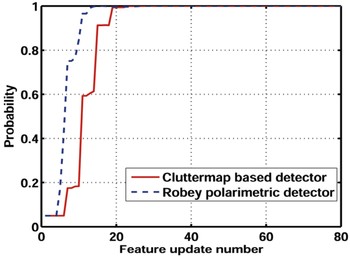
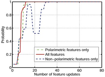
By doing so Fig. 6 shows the probability that an object is the same as in previous scans for both the (tuned) Robey primitive detector and the CMAP primitive detector. It can be seen that the CMAP detector converges somewhat faster than the Robey detector, in this case so much that it might compensate for the difference in primitive detection performance. Another relevant comment that can be derived from the analysis is that the polarimetric features have a noticeable contribution to the probability that an object is the same as in previous scans. Figure 7 shows the result per type of feature.
The probability that a contour is from the same object as the previous scan as a function of the update number. The horizontal axis counts the number of updates in the Bayes algorithm. The total span of the horizontal scale covers 20 antenna scans. No internal fluctuations of the test object.

The probability that a contour is from the same object as the previous scan as a function of the update number using the cluttermap-based detector. For each antenna scan, the feature update counter increments by 4. No internal fluctuation of the test object.

It can be seen that the polarimetric features are very important indeed. (Note: the line “polarimetric features only” seems to give a faster slope than the line “all features”. This is an artifact due to the drawing of the lines: the number of features involved in the lines is different and moreover the order in which they contribute in the Bayes algorithm is different.)
IV. EFFECT OF INTERNAL OBJECT RCS FLUCTUATIONS
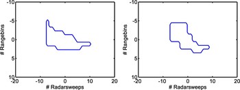
An issue that deserves further comment is whether or not the fluctuation of the scatterers composing the synthetic test object is of relevance. In the above analysis, the test object was composed of elementary scatterers, each with its own polarimetric back scatter matrix. In order to include some effects of intra-object fluctuation, the very same analysis as in Section III was performed while all individual elementary scatterers composing the compound extended object were changing their RCS according to the Swerling 1 fluctuation model (refer e.g. [Reference Skolnik8]), with uniform random phase per scatterer. For illustration, Fig. 8 shows two contours of the synthetic object. The scatterers composing the object have a total RCS with a negative exponential pdf. These contours are to be compared with the ones in Fig. 5, where exactly the same backgrounds were applied and thus the difference between the contours is exclusively due to the internal fluctuation of the RCS.
Two examples of how the original contour, as it was shown in Fig. 1, can be affected by clutter. The scatterers composing the object have a total RCS according to a negative exponential pdf.

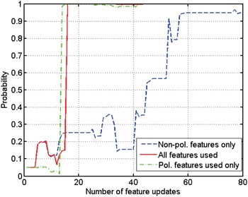
The probability that a contour is from the same object as in the previous scan, as presented in Fig. 7 for the case of no internal fluctuations, but this time for the case of internal fluctuations according to the above-described model, is shown in Fig. 9. It can be noted that the polarimetric features are less dependent on internal fluctuations than the non-polarimetric ones.
The probability that a contour is from the same object as the previous scan as a function of the update number using the cluttermap-based detector. For each antenna scan, the feature update counter increments by 4. Internal fluctuations according to the model as described.

V. EXPERIMENT WITH A NON-POLARIMETRIC VESSEL TRAFFIC MANAGEMENT RADAR
In the experimental campaign also a harbor radar was involved, and data were made available by TNO-DSS in The Hague. This radar provides a range resolution of 6 m and it has a beamwidth of 0.5°. Using the same cluttermap-based algorithms as described before, the eccentricity of the contour was developed as
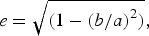
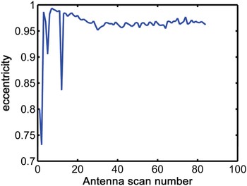
where b and a are the short and the long axis of the ellipse, respectively. The results of a sequence of some 90 antenna revolutions are shown in Fig. 10. This graph shows that the eccentricity is remarkably consistent, except for a few outlying points. These outliers were caused by plot splitting, one of the known problems in extended target extraction. The positional accuracy as measured for this case is estimated to be 0.05° and 2 m. The target involved was a large ship, not far from the radar antenna. In many such cases, the position is affected by glinting effects. The level of consistency suggests using this ellipticity as a discriminating feature and perhaps for support of target tracking as well.
The eccentricity of the ellipse circumscribing the target contour as a function of antenna scan number.

VI. DISCUSSION AND CONCLUSIONS
The multi-stage process of detection and extraction of extended targets is quite promising. The accuracy of the position, shown in Table 1, is very good and the features explored here offer good opportunities to discriminate between consistent objects on the one hand and clutter objects on the other, in particular considering that the scene is a rather difficult one. How to combine it with a primitive detector remains a topic for discussion. On the one hand, the detection performance based on the polarimetric detector has been shown to be competing with the well-known cluttermap solution and to be superior over order statistics and cell averaging CFAR processes. On the other hand, the contour circumscribing the object is distorted and incorrect elements from the background are included in the contour, leading to a lower quality of the features. So the main reason for the cluttermap-based process to be competitive in this extended object detection and extraction problem is due to the quality of the contour circumscribing the object. The polarimetric features measured within the contour are quite stable; hence they are the main reason for the cluttermap-based process to converge faster, as illustrated by Figs 4 and 5. Also some evidence was presented that internal fluctuations in extended objects have a considerable effect on non-polarimetric properties, while polarimetric features are more robust against such fluctuations.
It should be noted that Doppler effects were not included in the analysis.
ACKNOWLEDGMENT
This research was carried out in a project sponsored by the Dutch Ministry of Defence. The content represents the view of the authors.
 Piet van Genderen graduated in 1971 from the University of Twente in Enschede, The Netherlands in information theory. He joined the National Aerospace Laboratory (NLR) in Amsterdam in 1971, working on radar and processing for air traffic control. In 1979 he moved to Hollandse Signaalapparaten, now Thales. From 1994 he also holds a chair on radar system design at the Delft University of Technology in The Netherlands. His current research interests are in the design of wide band, agile radar, in particular in the design of waveforms and algorithms for extracting object features from the received video.
 Vsevolod Kovalenko graduated from Karazin's Kharkov National University in 1995 with a specialist degree in Applied Mathematics. Since 1996 he was with the Institute for Radiophysics and Electronics, Kharkov, Ukraine, where he developed algorithms for ground penetrating radar. In 2002 he joined the International Research Center for Telecommunications and Radar (IRCTR) of TU Delft to work on detection of buried landmines. The results allowed him to pursue a Ph.D. degree, which he obtained in 2006. Until 2008 he worked in the project of the current paper, where he developed algorithms for extended targets detection and feature extraction with polarimetric surveillance radar. Since 2008 he is with Fugro-Inpark B.V., a geo-engineering company. He is responsible for industrial subsurface mapping projects.