Introduction
Wireless communication is omnipresent in our daily lives, from wearables in personal area networks to laptops in wireless local area networks and phones in broadband cellular networks. In order to optimize wireless communication, radio channel models for various environments and frequency bands have been developed, ranging from office environments [Reference Honcharenko, Bertoni, Dailing, Qian and Yee1–Reference Rubio, Torres, Rodrigo Penarrocha, Perez, Fernandez, Molina-Garcia-Pardo and Reig6] to outdoor [Reference Pedersen, Mogensen and Fleury7–Reference Kristem, Bas, Wang and Molisch11] and industrial [Reference Tanghe, Joseph, Verloock, Martens, Capoen, Herwegen and Vantomme12–Reference Ai, Andersen and Cheffena15] environments. As the sub-6 GHz industrial, scientific, and medical (ISM) bands are getting crowded and future applications require higher data rates, development on mmWave channel models and radios is ongoing [Reference Maccartney, Rappaport, Sun and Deng3, Reference Wu, Wang, Sun, Huang, Feng, Yang and Ge4, Reference Hur, Baek, Kim, Chang, Molisch, Rappaport, Haneda and Park16–Reference Virk and Haneda22]. Most existing research investigates communication at mmWave frequencies in office or residential environments. However, wireless communication at mmWave frequencies also has a huge potential for industrial environments, such as low latency communication for valve control of machinery, video monitoring in remote areas, or a virtual reality operator providing assistance to machine operators.
The maritime industry is converging to a smart transportation ecosystem consisting of interconnected devices resulting in partially automated or fully autonomous ships [Reference Aslam, Corre, Belschner, Arockiaraj and Jäger23], with fewer crew members and increased on-board efficiency [Reference Im, Shin and Jeong24]. This paper considers the radio channel in a ship hull, a dangerous area where crew members are disconnected from the officers in the bridge and work in difficult circumstances. Wireless communication enhances the efficiency on board of the vessel by enabling automatic monitoring of equipment and therefore limiting the number of times crew members need to be in the ship hull [Reference Im, Shin and Jeong24]. It also increases safety by enabling video stream monitoring so an injured worker will be noticed faster and it can also replace existing wired communication links. The cables used for telecommunication and data transfer add to the deployment cost, noting that maritime cables should be corrosion resistant, fire and flame retardant, and certified [25]. By enabling wireless communication systems, the number of cables deployed in the vessel can be reduced, which not only decreases the weight of the vessel, but also decreases the cost and simplifies maintenance, as finding and replacing a broken cable is not straightforward.
Most research on maritime wireless communication addresses off-ship communication [Reference Parker26–Reference Xu, Shen and Wang31]. Sub-6 GHz radio channel measurements on board of a vessel were carried out in [Reference Balboni, Ford, Tingley, Toomey and Vytal32–Reference De Beelde, Tanghe, Yusuf, Plets and Joseph34], reporting a path loss exponent value of <2 for propagation within a metal compartment, which is in line with several other industrial environments [Reference Cheffena14]. Higher layer experiments of IEEE 802.15.4 based sensor networks on board of a vessel show a very good network reliability [Reference Brousseau, Kdouh, Zaharia, Grunfeleder and Zein35]. Modeling of 60 GHz indoor radio channels is already presented in [Reference Wu, Wang, Sun, Huang, Feng, Yang and Ge4, Reference Xu, Kukshya and Rappaport36–Reference Zaaimia, Touhami, Talbi, Nedil and Yagoub39].
In previous work, we presented path loss models at sub-6 GHz frequencies 868 MHz, 2.4 GHz, and 5.25 GHz [Reference De Beelde, Tanghe, Yusuf, Plets and Joseph34], and a Line-of-Sight (LOS) path model at 60 GHz [Reference De Beelde, Tanghe, Yusuf, Plets and Joseph34, Reference De Beelde, Tanghe, Yusuf, Plets, De Poorter and Joseph40]. The 60 GHz LOS path loss model from [Reference De Beelde, Tanghe, Yusuf, Plets, De Poorter and Joseph40] is extended with a beamwidth-dependent PL model in [Reference De Beelde, Tanghe, Yusuf, Plets and Joseph34]. The novelty of this paper is the analysis of the non-Line-of-Sight (NLOS) channel model, investigation of delay spreads, and the channel model implementation in a ray launching network planning tool. In our network planning tool, the transmitted signal is represented by a set of planar wavefronts where the attenuation is based on the channel model and the angular information is based on the room geometry and locations of the transmitter and receiver. Ray launching algorithms for determining channel characteristics and predicting network performance at mmWave frequencies are investigated in multiple papers [Reference Charbonnier, Lai, Tenoux, Caudill, Gougeon, Senic, Gentile, Corre, Chuang and Golmie41–Reference Zhou, Huang, Sun, Zhu, Wang and Yang45]. Most ray launching implementations consider transmission, specular reflection, and diffraction. Even though diffuse scattering accounts for up to 26% of the total received power [Reference Gentile, Papazian, Sun, Senic and Wang46], it is not considered in most ray launching implementations [Reference Charbonnier, Lai, Tenoux, Caudill, Gougeon, Senic, Gentile, Corre, Chuang and Golmie41].
In section “Methodology”, we first present the equipment and setups of the measurement campaign. We then provide the channel modeling and link budget methodology, followed by a presentation of the channel model implementation in a network planning tool for predicting network performance and conclude the section with a validation of the network planning tool. Section “Results” starts with a presentation of the LOS and NLOS channel modeling results and a link budget analysis based on the channel modeling results. We then provide the validation of the network planning tool and present network prediction simulation results for the ship hull environment. We conclude this paper in section “Conclusion”.
Methodology
We design a stochastic radio channel model for mmWave propagation in a ship hull, based on measurement campaigns we performed in an ocean-sailing vessel, and implement the channel model in a network planning tool.
Channel sounder
We use the Terragraph channel sounder which consists of two nodes, each containing a grid of 36x8 vertically polarized antennas with phase shifters and a Qualcomm QCA6438 transceiver chipset. The channel sounder is used by other institutions for outdoor 60 GHz channel modeling [Reference Aslam, Corre, Belschner, Arockiaraj and Jäger23, Reference Garcia Sanchez, Mohanti, Jaisinghani and Chowdhury47–Reference Sanchez and Chowdhury49]. The spacing of the antenna elements is 0.55 λ. The antenna grid results in a −3 dB beam width of 2.8 degrees, which we can steer in the azimuth plane from −45 to +45 degrees with respect to the node's boresight, in steps of 1.4 degrees. The channel sounder successively transmits IEEE 802.11ad frames, at channel 2 with center frequency 60.48 GHz and bandwidth 2.16 GHz, for each transmitter (TX) and receiver (RX) azimuthal beam configuration and performs a power measurement of the received signal. This results in a path loss angular profile (PLAP) that shows measured path loss as a function of both TX and RX azimuth angles, referred to as angle of departure (AoD) and angle of arrival (AoA) in the remainder of this paper. Sidelobes are present in the measured PLAP as the inter-element spacing is larger than λ/2 and there is only a phase adjustment for the antenna elements without gain tapering. The channel sounder is calibrated using a National Instruments mmWave transceiver. During the calibration, the chipset's reported received signal strength indicator (RSSI) is mapped to received power as a function of chip temperature, RX gain settings, and antenna configuration. Similarly, TX gain settings are mapped to equivalent isotropically radiated power (EIRP). During the measurements, the RSSI measurement data and transceiver configuration (antennas, TX and RX gains, chip temperature) are stored on a laptop for offline processing, during which the measured signal power is interpolated with calibration data resulting in corrected received power. Validation measurements of the channel sounder in a laboratory setting show an uncertainty of <1 dB in measured PL.
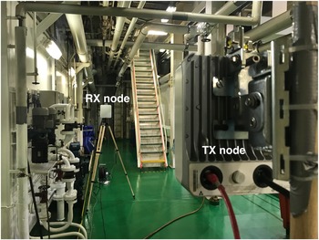
The channel sounder performs a 256-tap complex channel impulse response (CIR) estimation based on the training sequence of the IEEE 802.11ad preamble, using sampling rate of 3.52 GHz. The CIR estimation results in the root-mean-squared (RMS) delay spread with a time resolution of 0.28 ns. Both nodes are synchronized via an unshielded twisted pair (UTP) cable and the transmit power of 5 dBm results in an EIRP of 45 dBm. The dynamic range of the sounder is 50 dB. Figure 1 shows a picture of the channel sounder, with a distance of 3.75 m between the TX and RX nodes.
Terragraph channel sounder consisting of two nodes at distance 3.75 m along measurement track 1 in the engine room, synchronized via UTP and each having an antenna array of 288 antenna elements which allows beam steering in the azimuth plane.

Measurement setup
We performed LOS and NLOS measurements in the engine room and steering gear room of a 205 m long bulk carrier vessel with a gross tonnage of 33005. Measurements are performed along multiple tracks with increasing distance between the two nodes. For every track, the location of the TX node is fixed, while the RX node is moved away from the TX node.
During all measurements, the ship was moored in the harbor and no people were present in the engine and steering gear room. The vessel's main engine was not active, but an auxiliary engine used for electricity production was running. Even though this auxiliary engine was causing slight vibrations, the environment is considered static as there were no objects moving significantly and the vibrations due to the engine were much faster than the sweep time of the channel sounder.
Line-of-Sight
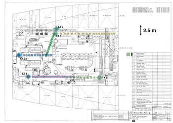
The locations of the LOS measurements in the engine room are shown in Fig. 2, in which the diamond markers indicate TX node locations and rectangular markers indicate RX node locations. The spacing of the nodes is chosen so that we have at least one PLAP measurement for every 0.25 m and at least two PLAP measurements on different tracks every 0.5 m. When combining all measurements, we obtain PL as a function of distance for distances ranging from 1.5 to 14.25 m with a spacing of 0.25 m.
Floorplan of the vessel's engine room with transmitter (TX, diamond symbols) and receiver (RX, rectangular symbols) locations for the Line-of-Sight measurements.

Non-Line-of-Sight
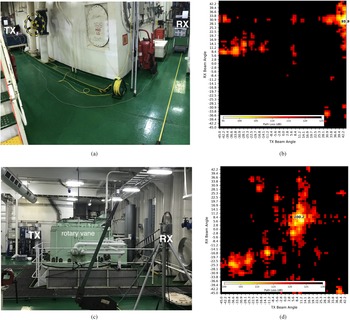
The LOS measurements provide NLOS information as every measurement consists of an azimuth scan, but we also performed NLOS measurements where the LOS path is obstructed and where we rotated the nodes in order to capture the most significant reflected paths. In the engine room, the receiving node was placed behind the corner (shown in Fig. 8a) whereas in the steering gear room the large rotary vane connected to the vessel's rudder blocked the LOS path (shown in Fig. 8c).
Channel modeling
The channel sounder provides received power for every TX-RX beam configuration, from which we obtain the double-directional radio channel. Based on the received power and EIRP we obtain measured path loss for distances ranging from 1.5 to 14.25 m. For the LOS measurements, we fit the minimum measured PL value, corresponding to an AoA and AoD of 0°, for each distance to the one-slope model presented in (1). The regression parameters are PL 0 (in dB), the PL at a reference distance d 0 of 1.5 m (as in [Reference Zaaimia, Touhami, Talbi, Nedil and Yagoub39]), and PL exponent n (-). The shadow fading term χ (in dB) results from a zero-mean normal distribution.

In order to model NLOS path loss in the vessel, we determine first-order reflected components in the PLAP of both LOS and NLOS measurements. For the LOS measurement tracks, the first-order reflections are obtained by selecting the local minimum in the PLAP for which the AoD is close to the additive inverse of the AoA and with a manual verification that the angle corresponds to the room geometry. The additional signal attenuation of this reflected path compared to the LOS path is caused by a longer path distance and by a reflection loss which depends on the incident angle and material properties. We calculate the distance of the reflected path via (2), with d LOS the distance of the LOS path and α the average of the AoA and inverse AoD.

For the NLOS measurements, we obtain the distance and incident angle from the room geometry and the locations of the TX and RX nodes. We obtain the reflection loss by subtracting the PL, calculated via (1) using the reflected path distance, from the measured PL. Even though most surfaces in the vessel are metallic, i.e. machinery, floor, and ceiling, the reflection loss is non-zero.
Link budget
Based on the developed channel models, we can predict throughput of the wireless link using the link budget equation presented in (3). The link budget returns the received power P R (in dBm) as a function of transmit power P T (in dBm), transmit and receiving antenna gains G T and G R (in dBi) and losses L T, L R (in dB), as well as the path loss PL (in dB). The received power should be higher than the receiver sensitivity P RS (in dBm) in order to obtain a certain data rate. Receiver sensitivity of the radio depends on the modulation and coding scheme (MCS) and therefore defines the maximum throughput that can be obtained for a fixed distance and transmit power. Receiver sensitivities for IEEE 802.11ad using a single carrier PHY are listed in Table 1 for different MCS.

Receiver sensitivity (P RS) and data rate (DR) as a function of modulation and coding scheme (MCS) for an IEEE 802.11ad radio [50]

Quality of service prediction tool
The channel model and radio characteristics are implemented in a quality of service (QoS) prediction tool for indoor wireless propagation [Reference Plets, Joseph, Vanhecke, Tanghe and Martens51], which calculates received power at every location based on stochastic channel models and material properties. Throughput is calculated via the link budget equation (3). The tool also includes a heuristic network planning algorithm which proposes access point locations that provide full coverage.
Algorithm
We have extended the prediction tool to include a 3-dimensional ray launching algorithm for directive mmWave communication. Via the QoS prediction tool, we estimate coverage based on the predefined location of access points. The environment is first discretized into a finite number of grid points and an access point is placed on the floorplan. At every grid point, a path information vector is stored with a configurable number of best paths to cover the grid point. A path is described by its interactions with the objects in the environment in order to reach the grid point. The path information vector not only stores the path loss associated to the paths, but also their distance, AoA and AoD. For each grid point, rays are launched in the azimuth and elevation plane from the access point, using a spherical coordinate system and with a configurable angle step size.
A flowchart of the ray launching methodology is presented in Fig. 3. The parameters of the algorithm are listed in Table 2. The azimuth angle θ ranges from 0 to 2π whereas elevation angle ϕ ranges from 0 to π. For each ray we define the interaction with the environment and calculate the associated losses, including PL and reflection loss. As the objects in the environment block communication, no transmission losses are taken into account. Path and reflection loss are calculated based on the channel model from Section “Methodology, channel sounder, measurement setup, channel modeling”. If the reflected ray reaches the accounted grid point, we store the path information vector and sort all path vectors of the grid point according to total loss. A ray is considered to reach a grid point if passes within 0.1 m from the grid point. If the ray does not reach the considered grid point, we define the next object interaction if the total loss is below the adjustable maximum path loss and if the maximum number of interactions has not yet been reached. We take into account reflection on metallic objects, as well as the floor and ceiling.
Flowchart presentation of ray launching algorithm.

Ray launching algorithm parameter configuration

We launch rays from every possible angle and do not consider the directivity of the TX antenna. Due to the narrow beam width of actual high-gain mmWave antennas, we define the path loss at every grid point as the path loss associated to the best path and we do not sum the path loss of the different paths as we would typically do for lower frequencies where omnidirectional antennas are used. The resulting coverage data should be interpreted as the maximum received power if the antennas are steered in the direction of the best path. Even though we associate the received power of the best path for each grid point, we store the best paths in order to compare the power received via the reflected path to the power of the LOS path. By using the best path for the PL calculation, we can speed up the simulation time as for grid points with a LOS path to the access point we do not need to use the ray launching algorithm.
Validation
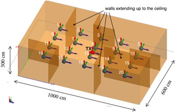
The ray launching algorithm has been validated by comparing simulation results to the commercial analytic electromagnetic wave (EM) solver FEKO based on the Method of Moments integral formulation of Maxwell's equations in combination with the uniform theory of diffraction. We compare the received power at different locations in a metallic room measuring 10 by 6 m, modeled as a perfect electrical conductor. The solver simulation takes into account direct, reflected, and diffracted paths. We perform simulations for 15 frequencies within a single IEEE 802.11ad channel and average the received power. We selected single precision data storage and enabled both normal geometry and mesh element size checks. The room with the receiver locations is shown in Fig. 4. An identical room is modeled in our prediction tool. Our prediction tool uses the channel model from section “Methodology, channel sounder, measurement setup, channel modeling”, i.e. the distance-related path loss is found via the LOS path loss model and the reflection loss uses the NLOS model. In order to validate our ray launching implementation via the FEKO simulation, we use the theoretic path loss according to Friis formula and assume zero reflection losses in the ray launching algorithm. We compare the received power of both simulations at all receiver locations.
Room measuring 10 by 6 m modeled in FEKO, with one transmitter at the center of the room and 20 receiver locations at height 1.5 m.

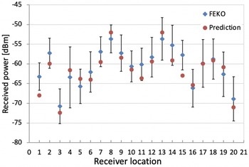
The results from FEKO show a high frequency dependency, which is caused by the omnidirectional antennas and the low coherence bandwidth which results in a pronounced multipath fading effect [Reference Haibing, Smulders and Herben52]. Figure 5 shows the predicted received power for each of the receiver locations from Fig. 4 as well as the simulated received power we obtained from the FEKO simulations, averaged over the full 2.2 GHz band of the IEEE 802.11ad channel and indicating the standard deviation of the 15 simulations.
Predicted received power and simulated received power via the analytical solver for all receiver locations shown in Fig. 4.

The predicted received power is within the standard deviation of the FEKO simulations for all receiver locations except location 1. The average difference between the predicted power and the average of the FEKO simulations is 1.9 dB. The locations for which the predicted received power is significantly below the received power from the simulations seem to correspond to locations where the receiver is in the shadow zone of a (metallic) wall. Our ray launching algorithm does not take into account diffracted rays; as FEKO takes into account diffraction, there is a higher received power.
Results
In this section, we start with presenting the LOS and NLOS channel models. Based on these channel models, we provide a link budget analysis in section “Results, Line-of-Sight channel model, non-Line-of-Sight channel model, link budget analysis”. In section “Results, Line-of-Sight channel model, non-Line-of-Sight channel model, link budget analysis, in-vessel simulations using QoS prediction tool”, we first provide the validation of the ray launching algorithm after which we present the QoS prediction analysis for the vessel.
Line-of-Sight channel model
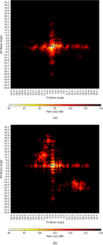
In order to illustrate a typical PLAP for a LOS measurement in the vessel, Fig. 6 shows the PLAP for two distances at measurement track 1. There is a strong LOS component for both AoA and AoD around 0°, and in Fig. 6 two reflected components are present at AoA and AoD around ± 10° and around ± 20°.
Path loss angular profile (PLAP). Measured path loss as a function of angle of arrival (AoA) and angle of departure (AoD) for Line-of-Sight measurement track 1. (a) Distance 2.75 m. (b) Distance 8.75 m.

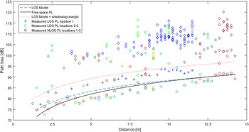
Figure 7 presents the minimum measured PL values as a function of distance for the different LOS measurement tracks shown in Fig. 2, together with the one-slope LOS model of the combined data set (dashed blue line) as well as free space PL (solid line). The circle colors represent the different measurement tracks. Also shown in the figure are the NLOS PL samples that we obtained from the LOS measurements’ PLAPs.
Measured Line-of-Sight (LOS) and non-Line-of-Sight (NLOS) path loss (PL) from the LOS measurement tracks, with LOS PL model for the engine room of a vessel as well as the free space PL. The different tracks are visualized with different colors; the LOS measurement data are visualized with a circle marker, and the NLOS data with a diamond symbol. The LOS data of track 1 are visualized by the plus symbol.

The fitted path loss PL 0 at reference distance d 0 = 1.5 m is 74.6 dB, which is higher than the free space PL of 71.6 dB at the same reference distance. However, the fitted PL exponent n of 1.68 is lower than the free space PL exponent of 2. The root mean squared error (RMSE) between the model and measurement data is 3.48 dB, which results in an added 95% shadow margin of 5.8 dB. The shadow margin added to the PL is shown in Fig. 7 as the red dotted line. For measurement track 1, which is parallel to the wall furthest away from the main engine, the measured PL is around 5 dB higher than free space PL, whereas the measured PL for locations 2–5 is close to or lower than free space PL.
Based on the CIR estimation, we obtain the RMS delay for every beam configuration. The average RMS delay for the significant taps of the CIR of the LOS beams is 2.96 ns and the standard deviation is 3.5 ns.
Non-Line-of-Sight channel model
From the PLAP of the LOS measurements shown in Fig. 6, we conclude that next to the strong LOS component, reflections are received. As the TX and RX angles are similar with opposite signs, and due to the geometry of the room, we suppose that these are first-order reflections. We also notice local minima in the PLAP for beam configurations with equal TX and RX angles, which are assumed to be second-order reflections. In order to assess the feasibility of NLOS communication from the LOS measurements, we select the main reflected paths with the lowest measured PL for which the absolute values of the TX and RX angles are approximately the same. The measured PL of the selected reflected path is visualized in Fig. 7 by diamond symbols.
We calculate the distance of these reflected paths via (2); but as the angles of arrival and departure are relatively small, the reflected path distances are close to the LOS path distance and we conclude that the additional path loss of the reflected path is mainly caused by reflection loss, rather than the loss caused by an increased distance. Figure 8 shows the PLAP for two NLOS measurements. For all the NLOS measurements, we determine the distance and incident angle of the reflected paths based on the vessel's floorplan, and calculate reflection loss as a function of incident angle by subtracting the LOS path loss using the reflected path distance from the measured PL. The reflection losses for all measurements as a function of incident angle are shown in Fig. 9, and for each reflection we indicate whether it is more likely to be a first-order or second-order reflection. The added loss of the first-order reflected paths is 16.0 dB, which increases up to 19.7 dB for the paths that are assumed to correspond to a second-order reflection. We do not see the angle-dependence that we would expect from the Fresnel reflection coefficient, and the reflection loss is larger than what we expect in a metallic environment. We can therefore assume that multiple close reflections occur due to the irregular shapes of the engine room's objects causing intra-cluster components. From a deployment perspective, it is clear that losses up to 30 dB need to be accounted for when using NLOS paths for communication.
Path loss angular profile (PLAP) with measured path loss as a function of angle of arrival (AoA) and angle of departure (AoD) for two non-Line-of-Sight (NLOS) measurement locations. (a) Receiver is behind the corner in engine room. (b) PLAP for corner crossing in engine room. (c) Vane obstructing the Line-of-Sight path in steering gear room. (d) PLAP with wall reflection to bypass vane obstruction.

Reflection loss as a function of incident angle.

The average RMS delay spread of the NLOS paths slightly increases to 4.32 ns, whereas the standard deviation remains 3.4 ns. The low RMS delay spread was expected as the channel sounder uses a narrow beam width. Figure 10 shows the histogram of all RMS delay spread data for both LOS and NLOS data. The histogram shows that even for NLOS measurement, the main share of paths has an RMS spread below 2.5 ns, even though a higher number of NLOS paths has a higher RMS delay spread compared to the number of LOS paths. On the one hand, this is caused by the specular reflection of a NLOS path, which does not cause a pulse to spread in time. On the other hand, the higher reflection losses that we measured (cf. Fig. 9), and the irregular nature of the engine room's objects cause NLOS paths with intra-cluster multipath, i.e. multiple reflections with reflection points close to each other. However, the path length of these intra-cluster components is similar, resulting in the same delay and therefore not significantly increasing the delay spread.
Histogram showing percentage of measured RMS delay spread values for both Line-of-Sight and non-Line-of-Sight paths.

Link budget analysis
Figure 11 presents throughput (in Mbps) as a function of distance using the link budget equation (3) for both LOS and NLOS scenarios and based on the PL model presented in the first part of this section. For the NLOS scenario, one reflection is considered with an average reflection loss of 16 dB added to the LOS PL model. We assume a transmit power P T of 13 dBm, an RX antenna gain G R of 8 dBi, a feeding loss L T of 2.5 dB, and a receiver loss L R of 0 dB. A 5.8 dB shadow margin is added and the receiver sensitivities that are listed in Table 1 are used. We compare a single-element patch antenna with a peak gain of 8 dBi as TX antenna to an 8x8 antenna array with a combined peak gain of 25 dBi.
Throughput and path loss as a function of distance for a Line-of-Sight and non-Line-of-Sight scenario.

From this link budget, we conclude that using a high-gain TX antenna is of utmost importance in order to achieve high data rates. When using a single-element patch antenna with a gain of 8 dBi as TX and RX antenna, the throughput rapidly decreases with distance, and communication via the reflected path is not possible. We see a leap in throughput at distance 5 m for the LOS scenario with a single patch antenna and at distance 3 m for the NLOS scenario with the antenna array as TX. This is caused by a constellation change, going from ${\pi \over 2}$ quadrature phase shift keying (QPSK) to a ${\pi \over 2}$
 binary phase shift keying (BPSK), resulting in a higher throughput for the QPSK used at MCS 6 compared to the BPSK from MCS 5, even though the receiver sensitivity using MCS 6 is lower.
In-vessel simulations using QoS prediction tool
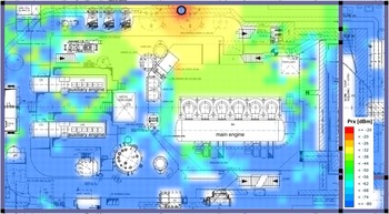
We used a free space PL model and assumed perfectly conducting surfaces with zero reflection loss for the validation of the ray launching algorithm. For predicting throughput and coverage via a simulation of received power in the ship hull based on the vessel's floor plan, we use the path loss model from Section “Results, Line-of-Sight channel model/non-Line-of-Sight channel model”. As we use the stochastic channel models, we can model the complex environment by simple geometric objects without the need for millimeter-level accuracy and the materials’ conductivity in order to predict received power. The ray launching algorithm is validated for the ship hull environment by comparing specific simulations to measurements from tracks 3 and 4. We select an access point location identical to the respective transmit location, and inspect the AoD and PL of the simulated best paths for grid points corresponding to receiver node measurement locations. For the validation simulations, the access point and receiver are positioned at the same height of 1.3 m. The LOS component follows the LOS PL model, the simulated AoD of the best reflected path is within 10 degrees of the measured AoD and the PL of the reflected path is within 3 dB of the measured PL. As the ray launching algorithm launches rays in the 360 degrees azimuth and 180 degrees elevation planes, floor and ceiling reflections also appear in the best path, but for tracks 3 and 4 these have a higher associated PL compared to the reflection on the nearby metallic machinery. Figure 12 shows the received power for every grid point at a height of 1.2 m when one access point is centrally placed at a height of 3 m. The simulation time on a laptop equipped with an Intel Core i5 processor is 325 min.
Expected received power based on ray launching algorithm and channel model. Using one access point with 13 dBm output power, antenna gain 25 dBi, and feeding loss 2.5 dB. The receiver antenna gain is 8 dBi. Skipping LOS paths from ray launching algorithm and using settings from Table 2.

When deploying an actual 60 GHz communication link, only one path will be used for communication from the TX to the RX node as the directive antennas have a narrow beam width. It therefore makes sense to only consider the LOS path when calculating path loss for grid points that have a LOS path to the access point. Furthermore, the simulation time decreases by 65% when skipping LOS grid points from the ray launching algorithm, compared to applying the ray launching algorithm to all grid points. As most of the objects in the engine room extend almost up to the ceiling, the probability of using a communication link that uses a ceiling reflection is low. We can therefore increase the elevation increment angle Δϕ without any significant influence on the prediction outcome. The computation time decreases by 52% when the elevation step angle is π/48 instead of π/100. Also increasing the azimuth increment angle Δθ to π/48 lowers the computation time by 77%. However, the resolution is lowered and some second-order reflected paths are lost. We use a maximum number of five reflections, but due to the large reflection loss, the received power is lower than the receiver sensitivity when there are more than two reflections. According to the link budget example of section “Link budget analysis”, we could have taken a lower maximum PL of 120 dB instead of 200 dB, which speeds up the simulation by 60%. It should be noted that the ceiling height of the engine room has no influence on the computation time as simulations with lower ceiling height have similar computation time.
If we calculate path loss of all best paths for the grid points with a LOS component and analyze the share of the power of the best reflected component to the total power of the LOS and reflected components, we see that for 57% of the grid points, no significant power is received via the reflected path. For the remaining 43% LOS grid points, the received power from the best reflected path accounts, on average, for 4.5% of the total received power, with a standard deviation of 1.5%.
Conclusion
The maritime industry is transitioning into a smart transportation ecosystem where interconnected devices are automatically monitored and remotely controlled. Wireless communication is a crucial element of this smart transportation ecosystem. In this paper, we have designed the directive channel model for Line-of-Sight and non-Line-of-Sight communication for communication at mmWave frequency 60 GHz in the hull of the ship. Even though the path loss of communication links with a Line-of-Sight path is close to free space path loss, the existence of multiple metallic objects creates severe blockage. On the other hand, there is a considerable reflection loss up to 20 dB, but communication via the first-order reflected path is possible if the total distance is limited. High-gain antennas are necessary and the corresponding narrow beam width results in a low RMS delay spread for both LOS and NLOS links, with an average of respectively 3.0 and 4.3 ns. The channel model is used for throughput and range calculations. A link budget is presented for Line-of-Sight and non-Line-of-Sight scenarios. With high-gain antennas, we obtain data rates over 3 GHz for Line-of-Sight communication, and data rates over 1 GHz for distances up to 8 m via a reflected path. We have implemented the channel model in a network prediction tool which can be used to predict received power based on predefined access point locations for environments similar to the engine and steering gear room of the vessel. For the received power prediction, we use a ray launching algorithm which is validated by comparison to an analytic EM solver. The ray launching algorithm takes into account propagation and reflection loss using the stochastic channel models presented in this paper. By using the stochastic channel models, we can predict received power without a detailed 3-D floorplan with millimeter-level machinery dimensions. No transmission through machinery is considered, due to the blocking nature.
For future work, we intend to generalize the ray launching algorithm so it can be used for other environments. Apart from reflection loss and path loss, we will implement partition loss for transmission through an object, as well as diffraction loss around an object. Based on the path information vector, containing object interaction information, we can characterize not only path loss for a certain grid point, but also channel parameters such as delay and angular spread.
Acknowledgment
This work was executed within the Internet-of-Shipping (IoS) research project and EOS project MULti-Service WIreless NETwork MUSE-WINET. IoS is co-financed by imec with support from Flanders Innovation & Entrepreneurship. The channel sounder has been granted as part of the Channel Sounder Program of the Telecom Infra Project (TIP). The authors would like to thank Ivan Renette and Franck Ntibashirakandi from Exmar Shipmanagement to facilitate the measurement campaign.
 Brecht De Beelde received the M.Sc. degree in Electrical Engineering from Ghent University (Belgium) in 2013. He started his career as an embedded SW engineer at the Low-Power Wireless Division of Qorvo, Inc where he worked on BLE and ZigBee communication controllers. He joined the WAVES research group of the Department of Information Technology (INTEC) of Ghent University in 2018, where he is currently working toward a Ph.D. degree. His research interests are channel modeling and wireless network planning in industrial environments and at mmWave and sub-Terahertz frequencies.
 Andrés Almarcha Lopéz received his degree in Telecommunication Engineering from the Technical University of Cartagena (Spain) in 2015. He started his career as validation engineer at NXP Smart Antennas Solutions. Prior to joining Barcelona Supercomputing Center in 2021 as a digital verification engineer, he was responsible for the verification of Bluetooth LE SoCs at Dialog Semiconductor. He currently works on the MareNostrum Exascale Experimental Platform.
 David Plets received the M.Sc. degree in Electrical Engineering from Ghent University (Belgium) in 2006 and joined the WAVES research group that same year. He obtained his Ph.D. degree in 2011 and has been an Assistant Professor since 2016. His current research interests include localization techniques and IoT for both industry- and health-related applications. He is also involved in the optimization of wireless communication and broadcast networks, with a focus on coverage, exposure, and interference.
 Marwan Yusuf received the M.Sc. degree in Electrical Engineering from Istanbul Medipol University (Turkey) in 2016 where he was a Research Assistant in the Communications, Signal Processing, and Networking Center (CoSiNC). He joined the WAVES research group 2018 and is currently working toward a Ph.D. degree. His research interests are measurement-based modeling of indoor and outdoor wireless propagation with emphasis on vehicular communication channels.
 Emmeric Tanghe received the M.Sc. degree in Electrical Engineering from Ghent University (Belgium) in July 2005 and joined the WAVES research group that same year. He obtained his Ph.D. degree in 2011 with a dissertation on the modeling of indoor and outdoor propagation through field measurements. He became a part-time professor in medical applications of electromagnetic fields in and around the human body in 2015. He continues his work on propagation modeling, covering indoor and outdoor propagation as well as propagation for wireless body area networks and medical implants.
 Wout Joseph received the M.Sc. degree in Electrical Engineering from Ghent University (Belgium) in 2000 and joined the WAVES research group that same year. He obtained his Ph.D. degree in 2005 with a dissertation on measuring and modeling of electromagnetic fields around base stations in order to assess the health effects of the exposure to electromagnetic radiation. Since October 2009, he is a professor in the domain of Experimental Characterization of wireless communication systems. His professional interests are electromagnetic field exposure assessment, in-body electromagnetic field modeling, electromagnetic medical applications, propagation for wireless communication systems, IoT, antennas and calibration. Furthermore, he specializes in wireless performance analysis and quality of experience.