Introduction
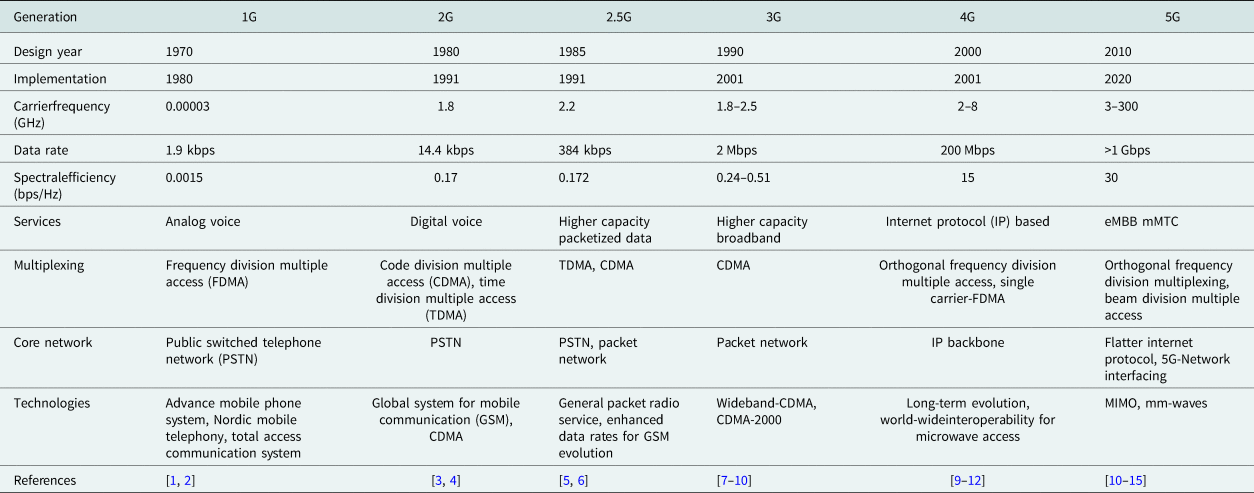
The rapid and dynamic increase of mobile data growth and the use of smart phones, tablets, and Wi-Fi hotspot devices are generating remarkable challenges for wireless service providers to win a battle against a global bandwidth scarcity. Today's cellular providers are committed to providing best quality, high-resolution, low latency, ultra-reliable videos and multimedia applications for wireless devices [Reference Jun, Kang, Kim and Kim1–Reference Rappaport, Sun, Mayzus, Zhao, Azar, Wang, Wong, Schulz, Samimi and Gutierrez3]. Fifth generation (5G) of cellular communication systems have been deployed in the world with each new mobile generation emerging in every decade since 1980. The first generation (1G) of analog FM cellular systems came in 1980, second-generation (2G) of digital technology in 1992, third generation (3G) in 2001, fourth-generation (4G), long-term evolution (LTE) in 2011, and 5G in 2020 [Reference Ghosh and Ratasuk4]. The evolution from 1G to 5G based on design, implementation, carrier frequency, data rate, spectral efficiency, latency, services, multiplexing techniques, core network, and name of the corresponding technologies are summarized in Table 1.
Comparison of different generations of wireless technologies

The 5G played an important role to provide seamless connectivity for the present wireless communication systems and overcomes the limitations of the previous wireless systems. Third generation partnership project (3GPP) defines three main 5G scenarios: enhanced mobile broadband (eMBB) at 10 Gbps, ultra-reliable and low latency communications (uRLLC) at 1 ms, and massive machine type communications (mMTC) at 1 million per km [Reference del Peral-Rosado, Raulefs, Lopez-Salcedo and Seco-Granados5, Reference Hong, Jiang, Yu, Zhou, Chen, Yu, Zhang, Yang, Pang, Jiang, Cheng, Al-Nuaimi, Zhang, Chen and He6]. In addition to ultra-low latency, highly reliable systems and to boost digital connectivity, 5G is in great demand. As correlated with the present 4G, 5G wireless communications are significantly different in various performance parameters such as gigabit per second (Gbps) data rate, end-to-end latency of <1 ms, exceptionally less energy consumption, and ultra-dense traffic volume. The band lies from 0.45 to 6.0 GHz specified as FR1 (frequency range 1) band, and from 24.25 to 52.6 GHz referred to as FR2 (frequency range 2) band. Due to the drastic increase in the mobile data demand, the spectrum available in the sub-6 GHz band is insufficient to fulfill the user's demands, so researchers and telecommunication companies are looking forward to a higher frequency spectrum from 6 to 300 GHz which will be employed for future wireless generations [Reference Osseiran, Monserrat and Marsch7, Reference Patnaik and Kartikeyan8].
ITU has declared the following spectrum for the deployment of 5G communications which consists of 3.4–3.6, 5–6, 24.25–27.5, 37–43.5, 45.5–50.2, 50.4–52.6, 66–76, and 81–86 GHz. Also, the Federal Communications Commission (FCC) has taken a major initiative to provide 5G additional spectrum in the following categories: high band: 24 GHz, 28 GHz, 37 GHz, 39 GHz, and 47 GHz, mid-band: 2.5 GHz, 3.5 GHz, and 3.7–4.2 GHz, low band: 600 MHz, 800 MHz, and 900 MHz, unlicensed: 6 GHz and above 95 GHz band. The mid-5G new radio (NR) bands such as n78 (3.3–3.8 GHz), n77 (3.3–4.2 GHz), n79 (4.4–5.0 GHz), n40 (2.3–2.4 GHz), n41 (2.496–2.690 GHz), n38 (2.57–2.62 GHz) are the active 5G NR networks in the 2–8 GHz frequency band. These bands have employed time-division duplexing, which is considered as a spectrum-efficient scheme and has the capability to enclose a wide geographical area for 5G communication systems for better coverage. TDD bands n78, n40, and n41 have become the industry concern to achieve higher data rates [Reference Marcus9–Reference Gomez-Barquero, Li, Fuentes, Xiong, Araniti, Akamine and Wang11].
The FR1 bands are envisaged to carry much of the traditional cellular mobile communication traffic. At the millimeter-wave (mm-wave) or FR2 band which lies in 24.25–52.6 GHz band, the signal-to-noise ratio (SNR) and signal-to-interference ratio (SIR) deteriorate because the electromagnetic waves suffer from the free space path loss and blockage. In the sub-6 GHz spectrum, the main attraction is on the 3.5 GHz band which has 400 MHz bandwidth (3.4–3.8 GHz), and is commercially available in many parts of the world, and can be used with the existing communication system hardware with minor changes [Reference Andrews, Buzzi, Choi, Hanly, Lozano, Soong and Zhang12–Reference Rodriguez-Cano, Zhang, Zhao and Pedersen15].
5G antenna designs in sub-6 GHz (2–8 GHz)
In this section, various designs of 5G antennas, antenna arrays, multiple-input multiple-output (MIMO) antennas and MIMO antenna arrays, beamforming antennas in the frequency range 2–8 GHz are discussed along with their designs and results.
2–8 GHz: single-element antennas
An important component of any wireless communication system is the antenna. A microstrip patch antenna is a pioneer in wireless communication devices. The development of microstrip patch antennas has offered many prospects in the present and future antenna designs, fabrication, and implementation [Reference Kushwaha, Karuppanan and Malviya16, Reference Malviya, Panigrahi and Kartikeyan17]. The main advantages of microstrip patch antennas are its low cost, light weight, low profile, and easy fabrication [Reference Pant, Malviya and Choudhary18]. Microstrip patch antennas come with different shapes such as rectangular, triangular, square, hexagonal, circular, annular ring, and elliptical [Reference Chen19–Reference Giauffret, Laheurte and Papiernik22]. In mm-wave frequency, size of the antenna, substrate property, and thickness are the important considerations. The microstrip antennas are designed and fabricated on dielectric substrates such as FR-4, Rogers RT/duroid 5880/5870, Taconic TLY-5, Taconic TLY-5, Megtron 6, Astra MT77, and Rogers RO4003C [Reference Gupta, Malviya and Charhate23, Reference Ndip, Le, Schwanitz and Lang24].
The conventional microstrip antennas have some limitations such as single-operating frequency, low impedance bandwidth, low gain, larger size, and polarization problems. There are a number of techniques that have been reported for enhancing the parameters of conventional microstrip antennas such as stacking, different feeding techniques, frequency selective surfaces (FSS), electromagnetic band gap (EBG), photonic band gap (PBG), and metamaterials [Reference Samineni, Khan and De25, Reference Bait-Suwailam, Siddiqui and Ramahi26]. Microstrip patch antennas are widely used in 5G sub-6 GHz and mm-wave systems. They are a strong choice for 5G base station antenna designs. However, its narrow bandwidth has confined its application to 5G base station antennas. Many techniques and solutions have been proposed by researchers to improve the bandwidth of patch antennas [Reference Coulombe, Koodiani and Caloz27–Reference Guha and Antar29]. A sub-6 GHz band will be able to cover the larger geographical areas for 5G coverage, but will not be able to provide high downlink speed [Reference Hussain30], while an mm-wave 5G technology will be able to provide high downlink speeds, but at the cost of less geographical area coverage. The frequency band 4.8–5.0 GHz of sub-6 GHz is allocated as an official band for 5G wireless systems [Reference Malik, Muzaffar, Mir and Moon31]. In the sub-6 GHz spectrum, the focus will be on the 3.5 GHz band having a 400 MHz bandwidth (3.4–3.8 GHz), as is commercially available globally.
The concept of metamaterials in the antennas at sub-6 GHz and mm-wave frequency has provided the improvement in antenna parameters such as gain and bandwidth. A metamaterial can be defined as an artificial homogeneous electromagnetic structure, designed for interaction and control of electromagnetic waves, and it contains unique properties which are not readily found in nature. For metamaterials, the structure size should be less than a quarter wavelength. Metamaterials can be classified based on their electromagnetic properties such as double negative (DNG) materials, left-handed (LH) materials, right-handed (RH) materials, negative refractive index (NRI) materials, magneto materials, and artificial magnetic conductors (AMCs). Metamaterials can also be termed as EBG, PBG, and defected ground structure (DGS) [Reference Han, Song and Sheng32–Reference Nguyen and Vu35].
A compact sub-6 GHz antenna was designed by employing an FR-4 substrate ($\epsilon _r = 4.4$ , thickness ${( h) } = 1$
 mm, loss tangent $( \tan \delta ) = 0.025$
 ) with a size of $20\times 12\, {\rm mm}^2$
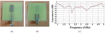
 . The desired frequency and wide bandwidth of 1.4–4.2 GHz were obtained which covered the 3.1–4.2 GHz 5G operating frequency band by employing three vertical slots, two horizontal slots in the patch, and the U-shaped ground structure in the ground plane. The antenna achieved a gain of 2.3 dBi. The fabricated views (front and back) and $S$
 -parameters are shown in Figs 1(a), 1(b), and 1(c) [Reference Gonzalez and Marquez36].
Slotted 5G antenna: fabricated (a) front view, (b) back view, and (c) $S$ -parameters. [Reference Gonzalez and Marquez36].

A multiband stack antenna which covered LTE and sub-6 GHz bands was designed by employing multilayers of FR-4 substrates each having ($\epsilon _r = 4.4$ , ${h} = 1.6$
 mm, $\tan \delta = 0.025$
 ) a size of $180\times 60\, {\rm mm}^2$
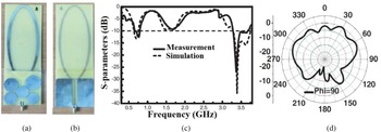
 in the dual operating band 0.66–0.79 and 3.28–3.78 GHz. In the design, the lower substrate consists of an elliptical patch which supports generation of 700 MHz band (LTE-R), and the upper substrate consists of five different circular patches which were made for resonating the antenna at 3.5 GHz (5G lower band) frequency and also contributed to enhance the bandwidth. The gain in the bands were 2.4 dBi at 0.7 GHz and 6.1 dBi at 3.5 GHz, respectively. The fabricated views (front and back) are shown in Figs 2(a) and 2(b). The $S$
 -parameters and radiation pattern are illustrated in Figs 2(c) and 2(d) [Reference Arya, Kim and Kim37].
Dual band 5G antenna: fabricated (a) front view, (b) back view, (c) $S$ -parameters, and (d) radiation pattern. [Reference Arya, Kim and Kim37].

To get a wide operating band and to cover n77/n78/n79 sub-6 GHz 5G bands, an antenna was designed on an FR-4 substrate ($\epsilon _r = 4.4$ , ${h} = 1.5$
 mm, $\tan \delta = 0.025$
 ) with a size of $30\times 20\, {\rm mm}^2$
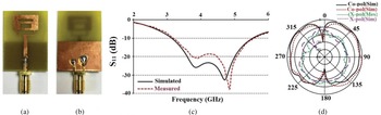
 and operated in the 3.15–5.55 GHz frequency band. The slotted patch and the partial ground were employed. The antenna achieved a gain of 1.87–2.69 dBi and radiation efficiency of 68.7–79.6% in the whole band. The fabricated views (front and back) are shown in Figs 3(a) and 3(b), $S$
 -parameters and radiation patterns are shown in Figs 3(c) and 3(d) [Reference Azim, Meaze, Affandi, Alam, Aktar, Mia and Islam38].
Dual band 5G antenna: fabricated (a) front view, (b) back view, (c) $S$ -parameters, and (d) radiation patterns. [Reference Azim, Meaze, Affandi, Alam, Aktar, Mia and Islam38].

To achieve a stable radiation pattern, a low cost and low profile antenna was designed on two layers of an FR-4 substrate ($\epsilon _r = 4.4$ , ${h}_1 = 1.5$
 mm, ${h}_2 = 0.4$
 mm, $\tan \delta = 0.025$
 ) with a size of $63\times 51.2\, {\rm mm}^2$
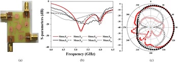
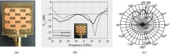
 which operated in the 2.8–5.2 GHz frequency band for 5G mobile communication systems. The top layer had three vertical dielectric pieces with two folded walls which were also designed in the upper layer of the substrate to support the patch. The three elliptical slots were employed for proper impedance matching. The antenna achieved a gain of 6.2 dBi and average radiation efficiency of 64% in the whole band. The fabricated front view is shown in Fig. 4 (a), $S$
 -parameters and radiation patterns are shown in Figs 4 (b) and 4(c) [Reference An, Li, Fu, Ma, Chen and Feng39].
Wide band 5G antenna: fabricated (a) front view, (b) $S$ -parameters, and (c) radiation patterns. [Reference An, Li, Fu, Ma, Chen and Feng39].

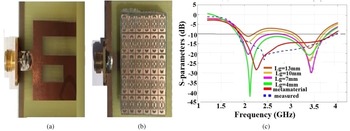
A patch antenna with DNG metamaterial was designed by employing a complementary split ring resonator (CSRR) on FR-4 dielectric substrate ($\epsilon _r = 4.4$ , ${h} = 1.62$
 mm, $\tan \delta = 0.025$
 ) with a size of $48\times 35\, {\rm mm}^2$
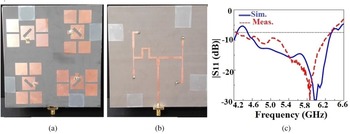
 for the n78 operating band in 3.3–3.8 GHz. The $6\times 6$
 CSRR was able to increase the gain and control the radiation pattern to minimize the specific absorption rate (SAR). The antenna achieved a gain of 5.5 dBi and radiation efficiency of 87% in the complete operating frequency band. The fabricated views (front and back) are shown in Figs 5(a) and 5(b). The $S$
 -parameters are shown in Fig. 5(c) [Reference Singh, Sohi and Gupta40].
Metamaterial-based antenna: fabricated (a) front view, (b) back view, and (c) $S$ -parameters. [Reference Singh, Sohi and Gupta40].

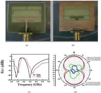
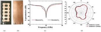
A low profile rectangular slot dual-band antenna was designed and fabricated on an FR-4 substrate ($\epsilon _r = 4.4$ , ${h} = 0.8$
 mm, $\tan \delta = 0.025$
 ) with a size of $36\times 31\, {\rm mm}^2$
 for operating in the lower 5G frequency bands such as n77 (3.3–4.2 GHz), n78 (3.3–3.8 GHz), and n79 (4.4–5 GHz). For creating a dual-band, the antenna was loaded with an inverted U-shaped stub in terms of ground arm and folded T-shaped feedline at the ground plane. The peak gain was 7.17 dBi with 80% radiation efficiency in the whole band. The fabricated views (front and back) are shown in Figs 6(a) and 6(b), and $S$
 -parameters and radiation patterns are shown in Figs 6 (c) and 6(d) [Reference Ishteyaq, Shah Masoodi and Muzaffar41].
Dual band rectangular slot antenna: fabricated (a) front view, (b) back view, (c) $S$ -parameters, and (d) radiation patterns. [Reference Ishteyaq, Shah Masoodi and Muzaffar41].

2–8 GHz: antenna arrays
There are many antennas having low gain, low directivity, and omnidirectional radiation patterns. Therefore, array antennas are required to provide high gain to single port antennas. In this case, multiple patches/elements are connected to the single port.
A $2\times 2$ graphene antenna array was designed on an FR-4 substrate ($\epsilon _r = 4.4$
 , ${h} = 1.6$
 mm, $\tan \delta = 0.025$
 ) with a size of $60\times 70\, {\rm mm}^2$
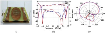
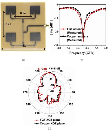
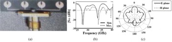
 for the 3.4–3.6 GHz frequency band, which covered sub-6 GHz 5G frequency band. A low loss T-type power divider was employed to excite the antenna array. The antenna array achieved a gain of 6.77 dBi with 99.99% radiation efficiency at 3.51 GHz resonant frequency. The fabricated front view is shown in Fig. 7(a), $S$
 -parameters and radiation patterns are shown in Figs 7(b) and 7(c). From the results, it was found that with the reflection coefficient, gain, and radiation pattern, the graphene antenna exhibited an equivalent performance as compared to a copper antenna [Reference Song, Huang, Liu, Zhang, Zhang, Liu, Wu and He42].
Graphene-based 5G antenna array: fabricated (a) front view, (b) $S$ -parameters, and (c) radiation patterns. [Reference Song, Huang, Liu, Zhang, Zhang, Liu, Wu and He42].

A $1\times 8$ circular fractal antenna array was designed on an FR-4 substrate ($\epsilon _r = 4.4$
 , ${ h} = 1.6$
 mm, and $\tan \delta = 0.025$
 ) with a size of $100\times 300\, {\rm mm}^2$
 which resonated at multiple frequencies. For obtaining fractal geometry, first, a circular slot of radius 3.3 mm was cut down from the center of each circular patch, then four more slots were cut again from each circular slot having a radius of 1.1 mm. The maximum gain achieved was 9.22 dBi with a radiation efficiency of 80.56% at 3.80 GHz resonant frequency. The fabricated front view and $S$
 -parameters are shown in Figs 8(a) and 8(b) [Reference Bhatia and Sivia43].
$1\times 8$ circular fractal antenna array: fabricated (a) front view and (b) $S$
 -parameters. [Reference Bhatia and Sivia43].

To convert linear polarization into right-hand circular polarization, a diagonal rectangular slot was etched at the middle of the antenna elements on a Taconic RF-35 substrate ($\epsilon _r = 3.5$ , ${h} = 3.04$
 mm, and $\tan \delta = 0.0018$
 ). The sequential-phase feeding network consists of three T-power dividers which circulate the input power to the outputs with equal magnitude and orthogonal in phase. The four parasitic elements were used to enhance bandwidth and gain. The $2\times 2$
 antenna array of dimensions 110 $\times$
 110 mm$^2$
 achieved a gain of 11.4–15.8 dBi in the operating band of 4.6–6.1 GHz. The fabricated (front and back) views are shown in Figs 9(a) and 9(b). The $S$
 -parameters are shown in Fig. 9(c) [Reference Tran and Park44].
Circularly polarized antenna array: fabricated (a) front view, (b) back view, and (c) $S$ -parameters. [Reference Tran and Park44].

2–8 GHz: MIMO antennas and MIMO antenna arrays
Wireless systems that employed antenna elements/arrays at both the transmitter and receiver are known as MIMO. It is one of the prime technologies that is used in both 4G and 5G wireless communication systems to overcome the disadvantages of single input single output (SISO). It works efficiently in non-line of sight (NLOS) wireless communication. The main advantages of MIMO antennas are to boost the spectral efficiency, enhanced channel capacity, premium services within limited power in dense scattering environments. The capacity of SISO and MIMO can be obtained using equations (1) and (2), respectively [Reference Malviya, Panigrahi and Kartikeyan45–Reference Malviya, Panigrahi and Kartikeyan47]:


where $N_t$ and $N_r$
 are the transmit and receiver antenna elements, $I_{ N_{r}}$
 is the $N_r\times N_r$
 identity matrix, $\rho$
 is the mean SNR per receiver branch, and superscript $\ast$
 denotes the Hermitian transpose, $H$
 is the channel matrix, and $H^{ \ast }$
 is the transpose of channel matrix.
In spite of many advantages, the design and fabrication of MIMO antenna in confined space is a big challenge in the 5G antennas. The crucial requirement of MIMO antenna is that the radiating elements should be as small as possible, well-matched, and should have low mutual coupling with nearby elements. Mutual coupling is induced among the radiating elements of the antennas because of the compactness and portability compulsion of the 5G wireless devices [Reference Malik, Patnaik and Kartikeyan48, Reference Molisch, Win, Choi and Winters49]. Mutual coupling can be defined as the energy absorbed by a closeby antenna when one antenna is radiating. The mutual coupling leads to change the input impedance, reflection coefficients, and radiation characteristics of the MIMO antennas. Mutual coupling can be defined by equations (3) and (4), respectively [Reference Arnold and Jensen50, Reference Malviya, Panigrahi and Kartikeyan51]:


where ${MC_{ij}}$ and ${d_{ij}}$
 are the mutual coupling and distance between the $i{\rm th}$
 and $j{\rm th}$
 antenna elements, respectively, $N$
 is the number of array elements, and $\alpha$
 is the parameter that dominates the coupling level [Reference Malviya, Malik, Panigrahi and Kartikeyan52].
The close proximity of radiating elements results in mutual coupling or correlation, which reduces the isolation and achievable performance [Reference Malviya, Parmar, Solanki, Gupta and Malviya53]. The performance of the MIMO system can be characterized by the parameters such as efficiency, radiation patterns, operating bandwidths, envelope correlation coefficient (ECC), mean effective gain (MEG), total active reflection coefficient (TARC), diversity gain (DG), and channel capacity [Reference Malviya, Panigrahi and Kartikeyan54]. The scattering parameters $S_{12}$ or $S_{21}$
 between the ports are not sufficient to include the effect of all $S$
 -parameters, therefore correlation coefficient is necessary to be calculated in MIMO antennas. It is a measure to describe how the two antennas are isolated from each other.
ECC is the square of the correlation coefficient. There are two ways to calculate the correlation coefficient, one is by employing $S$ -parameters as given in equation (5) and second one is determined by using far-field radiation patterns of the MIMO antennas as given in equation (6) [Reference Malviya, Panigrahi and Kartikeyan55]:


where $\rho _e$ is the correlation coefficient, ${F_1}{( \theta ,\; \, \phi ) }$
 and ${F_2}{( \theta ,\; \, \phi ) }$
 are the field radiation patterns of the antennas when any port is excited and other port is properly terminated to match the load and vice versa, and $\Omega$
 is the solid angle.
The ECC may be described by equation (7) [Reference Hassan and Sharawi56]:

where $\eta _{i}$ and $\eta _{j}$
 are the total efficiencies of the antennas $i$
 and $j$
 , and $\eta _{max}$
 is the multiplexing efficiency.
Similarly, the antenna DG is used to check the effectiveness of the diversity. For satisfactory operation of MIMO antennas, DG should be closed to 10 dB. It can be determined by calculating ECC, using equation (8) [Reference Chouhan, Panda, Gupta and Singhal57]:

MEG is one of the significant specifications for defining the performance of the antenna in real propagation or fading environments. It is the unique parameter that determines the effect of the antenna on the link budget. In general, MEG can be defined as the sum of gains of the NLOS and LOS components. It can be used to determine the average signal strength of each antenna and is given by equation (9) [Reference Malviya, Panigrahi and Kartikeyan58–Reference Kildal and Rosengren60]:

where i and j represent the antenna under testing and number of antennas, respectively.
The MEG can be expressed by equations (10) and (11), respectively [Reference Glazunov, Molisch and Tufvesson61, Reference Ando, Taga, Kondo, Kagoshima and Kubota62]:


where XPR is the cross-polarization ratio and $P_{\theta }$ , $P_{ \phi }$
 denote the weighted angular spectrum or weighted probability function of the angle of arrival of the stochastic components in the $\theta$
 and $\phi$
 polarizations, respectively.
Here, $\theta$ and $\phi$
 are the elevation and azimuth angles in a spherical coordinate system. Similarly, a scattering matrix is not sufficient for the proper definition of the efficiency and bandwidth of the MIMO antenna system, therefore TARC is more appropriate for characterization of the MIMO antenna system. For an $N$
 -port lossless antenna having [$S$
 ] as scattering matrix, TARC is defined as the square root of the ratio of the sum of the power available at all the ports subtracted by the radiated power to the total available power and is given by equation (12):

For $N$ -elements, TARC is defined by equation (13):

where $a_{i}$ and $b_{i}$
 are the incident and reflected signals, respectively, in a multiport network. $\Gamma ^ {t}_{a}$
 is a real-valued variable that lies between 0 and 1.
TARC is very useful and is an MIMO performance metric, as it considers the impact of random phases of incoming signals at each antenna element. For the $N$ -port set of MIMO antennas, if $\theta$
 is an independent and identically distributed Gaussian phase of a random process and reference phase $\theta _0$
 is neglected, then TARC can be defined by equation (14) [Reference Chae, Oh and Park63, Reference Fritz-Andrade, Jardon-Aguilar and Tirado-Mendez64]:

For ${N} = 2$ , above expression can be written as equation (15):

Many techniques have been explored by researchers to minimize the mutual coupling and enhance the isolation among the radiating elements. For example, DGS, EBG, FSS, neutralization lines, parasitic elements, metamaterial based structures, isolators such as T-shaped, circular, SRR, and CSRR, etc. are used to lower the effect of mutual coupling [Reference Arya, Kartikeyan and Patnaik65–Reference Kandwal, Sharma and Khah70].
The three double “F”-shaped defect was employed in DGS to enhance the isolation bandwidth of microstrip-slotted patch antenna designed on two layers of FR-4 substrate ($\epsilon _r = 4.4$ , ${ h} = 1.6$
 mm, $\tan \delta = 0.025$
 ) of dimensions $57.5\times 110\, {\rm mm}^2$
 having 0.09 mm distance between them. A $2\times 5$
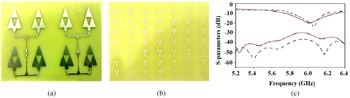
 asymmetrical arrays of EBG patches were also used to further minimize the isolation from 10 to 50 dB over the entire frequency band lies from 4.4 to 6.4 GHz. The antenna achieved a gain of 5.6 dBi with a radiation efficiency of 62% in the operating frequency band. The fabricated (front and back) views are shown in Figs 10(a) and 10(b), $S$
 -parameters and radiation patterns are shown in Figs 10(c) and 10(d) [Reference Sokunbi O71].
5G MIMO antenna array with DGS: fabricated (a) front view, (b) back view, (c) $S$ -parameters, and (d) radiation patterns. [Reference Sokunbi O71].

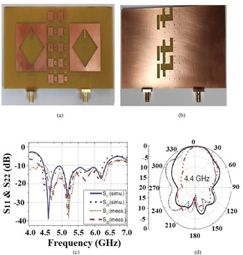
Similarly, for improving isolation and better impedance matching, an MIMO antenna array was designed on FR-4 epoxy substrate ($\epsilon _r = 4.4$ , ${ h} = 0.8$
 mm, $\tan \delta = 0.025$
 ) with a size of $20\times 35\, {\rm mm}^2$
 for 5G n78 band (3.3–3.8 GHz) with an altered T-shaped stub was placed between the two tapered rhombus-shaped radiators excited through tapered feeding with DGS. The antenna achieved a gain of 2.34 dBi with a radiation efficiency of 93% in the 3.34–3.87 GHz operating frequency band. An additional stub was also connected through the center of the radiator to obtain the required resonant frequency of 3.6 GHz. The isolation reported was >20 dB and 530 MHz bandwidth with ${\rm ECC}< 0.02$
 and $TARC< 0.5$
 . The antenna achieved gain of 2.34 dBi at 3.6 GHz resonant frequency. The fabricated (front and back) views are shown in Figs 11(a) and 11(b). The $S$
 -parameters are exemplified in Fig. 11(c) [72].
5G MIMO antenna array with grounded stub: fabricated (a) front view, (b) back view with T-shaped stub, and (c) $S$ -parameters. [72].

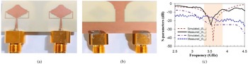
A $4\times 4$ MIMO antenna array with pattern diversity was designed on an FR-4 substrate ($\epsilon _r = 4.4$
 , ${ h} = 0.8$
 mm, and $\tan \delta = 0.025$
 ) with a size of $30\times 30\, {\rm mm}^2$
 for 5G n78 (3.3–3.6 GHz) and n79 (4.8–5 GHz) frequency bands. A parasitic patch acts as a decoupling structure consisting of a circular patch and four L-shaped arms employed on the top of the substrate were placed orthogonally. The design showed isolation >15 dB and the gain was 4.02 dBi at 5.95 GHz. The radiation efficiency was varied from 67 to 82% in the entire 4.58–6.12 GHz frequency band. The fabricated front view is illustrated in Fig. 12(a), the $S$
 -parameters and radiation patterns are delineated in Figs 12(b) and 12(c) [73].
Pattern diversity MIMO antenna: fabricated (a) front view, (b) $S$ -parameters, (c) and radiation patterns. [73].

A $4\times 2$ MIMO antenna array placed on the top of $7\times 7$
 metamaterial superstrate with a spacing of 5 mm between them was designed on an FR-4 substrate ($\epsilon _r = 4.4$
 , ${ h} = 1.6$
 mm, $\tan \delta = 0.025$
 ) with a size of $107\times 58\, {\rm mm}^2$
 . The advantages of DNG unit cell superstrate has as compared to MIMO antenna array without DNG superstrate are the bandwidth increased from 210 MHz (5.65–6.4 GHz) to 750 MHz (5.91–6.12 GHz), boost the gain from 11.1 to 14.05 dBi, and enhanced the isolation from 30 to 38 dB. The radiating efficiency was 96.2% at 5.6 GHz resonant frequency. The fabricated (front and back) views are shown in Figs 13(a) and 13(b). The $S$
 -parameters are shown in Fig. 13 (c) [Reference Ojo, Jamlos, Soh, Jamlos, Bahari, Lee, Al-Bawri, Abdul Karim and Khairi74].
$4\times 2$ MIMO antenna array: fabricated (a) front view, (b) back view, and (c) $S$
 -parameters. [Reference Ojo, Jamlos, Soh, Jamlos, Bahari, Lee, Al-Bawri, Abdul Karim and Khairi74].

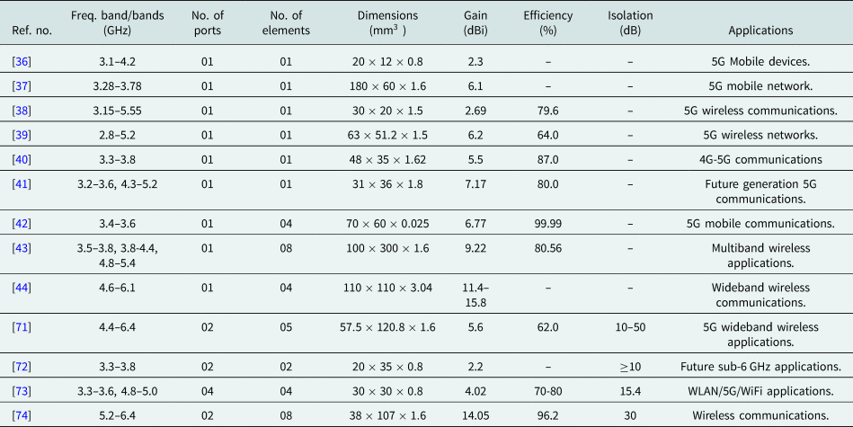
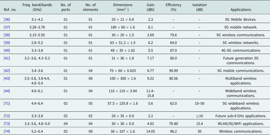
The comparison of the sub-6 GHz antenna, antenna arrays, and MIMO antennas are given in Table 2.
Comparison of single-element antennas, antenna arrays, MIMO antennas, and MIMO antenna arrays for 2–8 GHz frequency band
5G antenna designs in 24–40 GHz frequency bands
In this section, various designs of 5G antennas, antennas arrays, MIMO antennas, MIMO antenna arrays, and beamforming antennas from frequency range 24 to 40 GHz are discussed along with their designs and results.
24–40 GHz: single-element antenna and antenna arrays
In this section, the 5G antenna designs with 24–40 GHz frequency range are covered with all the details. As the spectrum lying in the sub-6 GHz is becoming congested due to the increasing demand for high data rates, the necessity of mm-wave bands such as 28, 38, 60, and 73 GHz for 5G communication systems is vital. In China 24.25–27.5 and 37–42.5 GHz and in the USA 27.5–28.5 and 37–39 GHz bands have been determinant as prominent frequency bands for 5G wireless communication systems. The high-frequency bands are able to give a fast speed and high capacity, depending on the distance between the users and the cell site [Reference Ancans, Bobrovs, Ancans and Kalibatiene75–Reference Yost77].
The telecommunication companies such as NTT DOCOMO, CMCC, KT, Verizon, T-mobiles, and AT&T are planning to utilize the 24.25–29.5 and 37–40 GHz 5G frequency spectrum and companies such as Orange, Telecom Italia, and British Telecom are going to support 31.8–33.4 GHz frequency band. Millimeter spectrum provides higher bandwidth and capacity. However, as the frequency increases the mm-wave suffers from propagation loss, blockage, and interference. In addition, mm-wave frequency bands suffer from atmospheric losses for example as the size of raindrops is comparable to mm-wave wavelength so scattering loss has occurred. The total attenuation caused by atmospheric gases and rain is given by equation (16) [Reference Wang, Li, Ding, Miao, Li and Wang78, 79]:

where $\gamma _{G}$ is the sum of the attenuations due to oxygen and water vapor, respectively, $\gamma _{R}$
 is attenuation (dB/km) due to rainfall, $R$
 is the rain rate (mm/h), $k$
 and ${\alpha }$
 are coefficients which depend on frequency $f$
 (GHz).
At 28 GHz the path loss in dense urban NLOS environment is given by equation (17), for ${ d}< 100$ and equation (18) for ${ d}> 100$
 , respectively:


where $d$ is the distance in m.
At 28 GHz the path loss is significantly higher as compared to the sub-6 GHz band, according to the free space path loss given by equation (19) an additional 22.9 dB of losses can take place from 2 to 28 GHz frequency range. To mitigate such losses antenna array size of higher gains, MIMO antenna, massive MIMO antennas, and beamforming techniques are highly needed and desirable:

The sum of electric fields from two-element arrays separated by distance d is given by equation (20):

where $E_1$ and $E_2$
 are the electric fields by first and second elements and $\psi$
 is the phase difference which is define by equation (21) [80, Reference Seker, Guneser and Arslan81]:

where $k = {2 \pi }/{ \lambda }$ .
The radiation pattern of an antenna array can be obtained by the product of the radiation pattern of a single element multiplied by an array factor (AF) which is given by equation (22):

Consider $\alpha$ be the progressive shift between the $N$
 radiating elements then the AF is obtained by equation (23):

For the circular array the AF can be calculated by equation 24 [Reference Ioannides and Balanis82, Reference Karmakar83]:

where $r_1 = \cos ( 2\pi {n}/{N}) \sin \theta \cos \phi$ and $r_2 = \sin ( 2\pi {n}/{N})$
 $\sin \theta \sin\phi$
 .
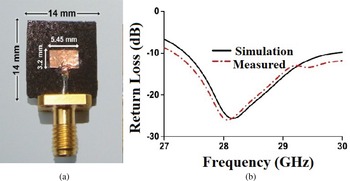
There are many antennas and antenna arrays designed for 5G applications for 28–40 GHz operating frequency band using different feeding techniques such as inset feed, series feed, corporate feed, and corporate-series feed [Reference Yadav, Parmar, Malviya and Nitnaware84–Reference Pant, Malviya and Choudhary86]. A 28 GHz patch antenna was designed on a manganese zinc ferrite substrate ($\epsilon _r$ = 7, $h = 1.00$
 mm, $\tan \delta$
 = 0.003) with a size of 14 $\times$
 14 mm$^2$
 . The $-10$
 dB impedance bandwidth was 27.23–29.89 GHz and the gain achieved was 5.44 dBi with a radiation efficiency of 93% at 28 GHz resonant frequency. The fabricated front view is shown in Fig. 14(a) and $S$
 -parameters are shown in Fig. 14(b) [Reference Rahman, Ng M, Ahmed, Alam, Singh and Islam87].
5G single patch antenna: fabricated (a) front view and (b) $S$ -parameters. [Reference Rahman, Ng M, Ahmed, Alam, Singh and Islam87].

To enhance the gain, a $1\times 4$ elliptical patch antenna array was designed on Rogers RT/duroid 5880 substrate ($\epsilon _r = 2.2$
 , ${ h} = 0.508$
 mm, $\tan \delta = 0.0013$
 ) with a size of $6\times 6\, {\rm mm}^2$
 and operated at 28 and 45 GHz resonating frequencies. The antenna array achieved a gain of 7.6 dBi and radiation efficiency of 85.6% in the operating frequency band at 28 GHz. SAR for 28 GHz reported was 1.25 W/kg. The fabricated view, $S$
 -parameters, and radiation patterns are shown in Figs 15(a), 15(b), and 15(c) [Reference Khattak, Sohail, Khan, Barki and Witjaksono88].
$1\times 4$ 5G elliptical antenna array: fabricated (a) front view, (b) $S$
 -parameters, and (c) radiation patterns. [Reference Khattak, Sohail, Khan, Barki and Witjaksono88].

For obtaining low side lobe level and bandwidth enhancement, tapering is employed in array antennas. Amplitude tapering can be done by varying the width of the radiating elements. Amplitude tapering function is defined by equations (25) and (26), respectively [Reference Yuan, Yuan and Li89, Reference Singh, Sarwade and Ray90]:


where $\alpha$ is the pedestal height and $w[ 1]$
 is the new coefficient which is obtained by previous weight $w[ k]$
 .
Amplitude tapering in binomial array is done by varying the effective width of the radiating elements according to equations (27) and (28), respectively [Reference Chopra and Kumar91, Reference Jian, Chen, Chen and Li92]:


where ${k} = 0,\; 1,\; 2,\; \ldots ,\; N-1$ .
A broadband hexagonal antenna array having dimensions of $45\times 20\, {\rm mm}^2$ was designed on Rogers RT/duroid 5880 substrate ($\epsilon _r = 2.2$
 , ${ h} = 0.254$
 mm, $\tan \delta = 0.0009$
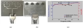
 ) in 25.05–34.92 GHz operating band. The geometry of the antenna array utilized two hexagonal wire loops which are concentric and separated by a small gap. The combination of loop and gap gives the flexibility to control the resonant frequency. The single element is backed by a ground loop of the same dimension as that of top wire loops to improve the broadside radiations. A series of vias were used in an inverted U-shape manner. The gain and radiating efficiency achieved were found to be 10.12 dBi and 85% at 28 GHz. The fabricated (front and back) views are shown in Figs 16(a) and 16(b). The gain–efficiency plot is shown in Fig. 16(c) [Reference Ullah and Tahir93].
$1\times 4$ broadband 5G antenna array: fabricated (a) front view, (b) back view, and (c) gain–efficiency plot. [Reference Ullah and Tahir93].

To increase the gain and efficiency, a single port compact 12 element patch antenna array was designed on Rogers RT/duroid 5880 substrate ($\epsilon _r = 2.2$ , ${ h} = 0.79$
 mm, $\tan \delta = 0.0009$
 ) with a size of $51.44\times 18.34\, {\rm mm}^2$
 in 27.06–28.35 GHz operating band. The four corners of the patches were chopped at an angle of $45^\circ$
 to get minimum return loss. The gain reported was 16.0 dBi with 93.5% radiation efficiency at 28 GHz. The fabricated (front and back) views are shown in Figs 17(a) and 17(b). The $S$
 -parameters and $E$
 -field radiation patterns are shown in Figs 17(c) and 17(d) [Reference Malviya and Gupta94].
High gain antenna array: fabricated (a) front view, (b) back view, (c) $S$ -parameters, and (d) radiation patterns. [Reference Malviya and Gupta94].

A 13-circular radiating element grid antenna was designed having dimensions $21.5\times 23\, {\rm mm}^2$ on Rogers RT/duroid 5880 substrate ($\epsilon _r = 2.2$
 , ${ h} = 0.79$
 mm, $\tan \delta = 0.0009$
 ) at 30 GHz resonant frequency. The antenna array achieved a gain of 9 dBi and radiation efficiency of 80% in the operating frequency band 27.5–33.3 GHz. The fabricated view, $S$
 -parameters, and radiation patterns are shown in Figs 18(a), 18(b), and 18(c) [Reference Jilani, Abassi and Alomainy95].
5G grid antenna array: fabricated (a) front view, (b) $S$ -parameters, and (c) radiation patterns. [Reference Jilani, Abassi and Alomainy95].

For 5G, high gain and compact antennas are highly desirable. A tapered high gain and compact antenna array with series and parallel feeds was designed on Rogers RT/duroid 5880 substrate ($\epsilon _r = 2.2$ , ${ h} = 0.79$
 mm, $\tan \delta = 0.0009$
 ) with a size of $30\times 26\, {\rm mm}^2$
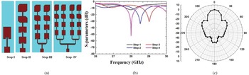
 in 27.70–28.78 GHz operating band. The gain was 17.7 dBi with 93.36% radiating efficiency at 28 GHz resonant frequency. The design steps are shown in Fig. 19 (a). The return loss of all the design steps and $E$
 -field radiation patterns are shown in Figs 19(b) and 19(c) [Reference Pant, Malviya and Choudhary96].
16 elements antenna array: (a) design steps, (b) $S$ -parameters, and (c) radiation patterns. [Reference Pant, Malviya and Choudhary96].

In 5G antennas, the bandwidth enhancement could be made by employing feeding techniques such as proximity and aperture coupled because they provide wider bandwidths and prevent undesired radiation as compared to the direct feed structures. A compact size, high gain broadband $6\times 5$ proximity coupled antenna array was designed on two stacked Taconic TLY-5 ($\epsilon _r = 2.2$
 , ${ h} = 0.51$
 mm, $\tan ( \delta ) = 2.20$
 ). Amplitude tapering was applied by using Dolph–Chebyshev polynomials to the individual patch elements to obtain low sidelobe levels up to $-18$
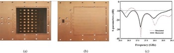
 dB. However, it produced reflection which was overcome by located slits in the appropriate position. The antenna achieved a gain of around 21 dBi over an operating bandwidth of 27.5–28.5 GHz. The fabricated front and back views are shown in Figs 20(a) and 20(b). The $S$
 -parameters are shown in Fig. 20 (c) [Reference Diawuo and Jung97].
6 $\times$ 5 proximity coupled antenna: fabricated (a) front view, (a) back view, and (c) $S$
 -parameters. [Reference Diawuo and Jung97].

A Franklin antenna is important for the 5G applications due to its small size, simple structure, high gain, and capability to minimize spurious radiation and surface wave excitation. A multi resonance, compact, and high gain $3\times 3$ Franklin antenna array was designed on a Rogers 5880 substrate ($\epsilon _r = 2.2$
 , ${ h} = 0.79$
 mm, $\tan \delta = 0.0009$
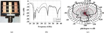
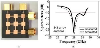
 ) in the operating band of 28 GHz and 37–39 GHz. A Franklin antenna consists of two radiating elements, the first one is the patch and the folded stub. The gains achieved for multiple bands were 13.5 dBi at 29 GHz, 8.33 dBi at 33 GHz, and 9.58 dBi at 38 GHz respectively. The fabricated front view is shown in Fig. 21(a), $S$
 -parameters and the radiation patterns are shown in Fig. 21(b) and 21(c) [Reference Jilani and Alomainy98].
$3\times 3$ Franklin antenna array: fabricated (a) front view, (b) $S$
 -parameters, and (c) radiation patterns. [Reference Jilani and Alomainy98].

24–40 GHz: MIMO antennas and MIMO antenna arrays
MIMO systems, using an array of antennas at the transmitter and receiver link, provide drastically enhanced data capacity. The ability to achieve this high capacity is greatly determined by the shape, size, and distance between the antennas. There are several studies available in the literature which focus on MIMO antennas and MIMO antenna arrays operating in the mm-wave band for 5G wireless applications. MIMO antennas minimize the effect of multipath propagation by providing a high data rate, increased capacity, and link reliability, which are the main characteristics of 5G. However, the difficulties related to MIMO antenna designing is to design compact antenna elements with reduced mutual coupling and high isolation [Reference Yadav and Malviya99, Reference Malviya, Gupta, Parmar, Solanki and Malviya100].
A two-element MIMO antenna was designed on a Rogers RT/Duroid 5880 substrate ($\epsilon _r = 2.2$ , ${ h} = 0.38$
 mm, $\tan \delta = 0.0009$
 ) with a size of $12\times 24\, {\rm mm}^2$
 in the operating band of 28.2–30.7 GHz. The ECC value reported was <0.001. The fabricated front view and $S$
 -parameters are shown in Figs 22(a) and 22(b) [Reference Hasan and Seo101].
Two-element MIMO-antenna: fabricated (a) front view and (b) $S$ -parameters. [Reference Hasan and Seo101].

A four-element high gain MIMO antenna was designed and fabricated on a Rogers-5880 substrate ($\epsilon _r = 2.2$ , ${ h} = 1.57$
 mm, $\tan \delta$
 = 0.0009) with dimensions of $80\times 80\, {\rm mm}^2$
 . The antenna gain was 12 dBi with 70% radiating efficiency in the frequency band of 23–40 GHz. The isolation reported was >20 dB and ${\rm ECC}< 0.0014$
 . The fabricated front view and $S$
 -parameters are shown in Figs 23(a) and 23(b) [Reference Sehrai, Abdullah, Altaf, Kiani, Muhammad, Tufail and Rahman102].
Four-elements MIMO antenna: fabricated (a) front view and (b) $S$ -parameters. [Reference Sehrai, Abdullah, Altaf, Kiani, Muhammad, Tufail and Rahman102].

DGS is one of the techniques to suppress the surface wave and improve the performance of an antenna or antenna array. It also helps to reduce the mutual coupling of MIMO elements. An MIMO antenna was designed on a Rogers RT/duroid 5880 substrate ($\epsilon _r = 2.2$ , ${h} = 0.8$
 mm, $\tan \delta = 0.0009$
 ) of dimensions $12\times 25.4\, {\rm mm}^2$
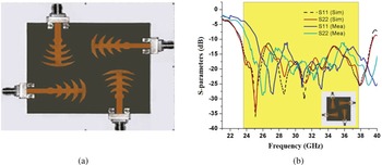
 in the operating bands of 26.83–33.13 and 34.17–38.13 GHz, respectively. To improve the bandwidth and gain, T-shaped patch was employed in the upper layer of the substrate and the bottom layer utilized the DGS and CSRR. The peak gain measured was 7.2 dBi in the complete operating band. The ECC and DG values were <0.005 and close to 10, respectively. The fabricated (front and back) views are shown in Figs 24(a) and 24(b). The $S$
 -parameters are shown in Fig. 24(c) [Reference Venkateswara Rao, Madhav, Krishna, Usha Devi, Anilkumar and Prudhvi Nadh103].
5G MIMO antenna with T-stub fabricated: (a) front view, (b) back view, and (c) $S$ -parameters. [Reference Venkateswara Rao, Madhav, Krishna, Usha Devi, Anilkumar and Prudhvi Nadh103].

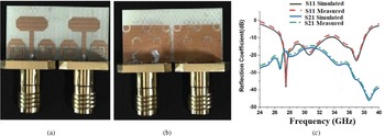
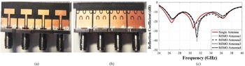
A wide bandwidth four-element MIMO antenna was designed on a Rogers RT/duroid 5880 ($\epsilon _r = 2.9$ , ${ h} = 0.254$
 mm, $\tan ( \delta ) = 0.0009$
 ) of dimensions $12\times 50.8\, {\rm mm}^2$
 in the operating band 25.1–37.5 GHz. The four T-shaped radiators were designed on top of the substrate and a partial ground loaded with multiple split-ring slots was employed at the bottom. The gain was above 5.0 dBi with 80% radiating efficiency in the complete operating band. The fabricated front view, back view, and $S$
 -parameters are shown in Figs 25(a), 25(b), and 25(c) [Reference Jilani and Alomainy104].
DGS-based four-element MIMO antenna array: fabricated (a) front view, (b) back view, and (c) $S$ -parameters. [Reference Jilani and Alomainy104].

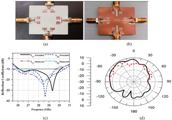
A four-port MIMO antenna array for 5G MIMO applications was designed and fabricated on a Rogers R04350B substrate ($\epsilon _r = 3.66$ , ${ h} = 0.79$
 mm, $\tan \delta = 0.0037$
 ) having dimensions of $30\times 35\, {\rm mm}^2$
 . To improve the radiation characteristics and reduce the mutual coupling in the 25.5–29.6 GHz operating band the ground plane defected with the three different slots such as rectangular, circular, and zigzag. The isolation reported between the antennas was 17 dB. The gain and radiating efficiency were 8.3 dBi and 82% respectively with $-10$
 dB impedance bandwidth lies in 25.5–29.6 GHz and ECC < 0.01, and DG > 9.96 were calculated respectively. The fabricated front view, back view, $S$
 -parameters, and radiation patterns are shown in Figs 26(a), 26(b), 26(c), and 26(d) [Reference Khalid, Iffat Naqvi, Hussain, Rahman, Mirjavadi, Khan and Amin105].
Four-element MIMO antenna array with multiple DGS: fabricated (a) front view, (b) back view, (c) $S$ -parameters, and (d) radiation patterns. [Reference Khalid, Iffat Naqvi, Hussain, Rahman, Mirjavadi, Khan and Amin105].

EBG structure-based antennas are very popular in mm-wave applications because of their specific band gap characteristics at particular or desired frequency bands. EBG structures can resonate at lower frequencies depending upon the shape and dimension of unit cells, therefore are capable of antenna miniaturization. An EBG consists of periodic or non-periodic arrangement of unit cells which can create high impedance to block the unwanted surface waves for all angles and for all polarization states and field coupling. As a result the gain, efficiency and other parameters of the antennas can be improved. Equations (29)–(32) are generally employed to extract the permittivity and permeability [Reference Peddakrishna, Khan and De106–Reference Yang and Rahmat-Samii109]:


where $z$ is the normalized impedance, $k_0$
 is the wave number, and $d$
 is the thickness of the substrate.
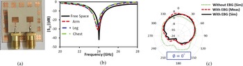
In view of mm-wave 5G wearable applications, a two-element MIMO antenna was designed on a flexible Rogers RT/duroid 6002 substrate of dimensions $19.04\times 15.06\, {\rm mm}^2$ ($\epsilon _r = 2.94$
 , ${ h} = 0.254$
 mm, $\tan \delta = 0.0012$
 ). A $5\times 5$
 EBG was employed on the back which enhanced the gain by 1.9 dBi and decreased the impact of harmful radiations on the human body. The gain and radiation efficiency achieved were 6.0 dBi and 80.5% at 24 GHz resonant frequency respectively. The fabricated front view, $S$
 -parameters, and radiation patterns are shown in Figs 27(a), 27(b), and 27(c) [Reference Iqbal, Basir, Smida, Mallat, Elfergani, Rodriguez and Kim110].
MIMO antenna with EBG structure: fabricated (a) front view, (b) $S$ -parameters, and (c) radiation patterns. [Reference Iqbal, Basir, Smida, Mallat, Elfergani, Rodriguez and Kim110].

Phased array antenna
A phased array antenna is a combination of antenna elements collected together such that the combined radiation pattern intensifies in the desired direction and diminishes in the undesired direction. Phase antennas reinforced the radiated energy in the desired direction. The gain of the phased array can be calculated by using equation (33), if the correct location of the array element's phase center is unknown:

The gain of the phased array, when the accurate location of the array element's phase center is given by equation (34):

where $G_1$ , $G_2$
 ,…, $G_N$
 are gains of each antenna elements, $k$
 is the wave number, $\theta$
 is the angle between the array scanning direction and boresight direction, and $\beta _{1}$
 ,…, $\beta _{N}$
 are the phase shifts in each element's feed [Reference Syrytsin, Zhang, Pedersen and Morris111, Reference Yu and Kamarudin112].
A $3\times 3$ phased antenna array with four feed ports and controlled by four-phase shifters was designed on an RT/duroid 5880 substrate ($\epsilon _r = 2.2$
 , ${ h} = 0.254$
 mm, $\tan \delta = 0.0009$
 ) of dimensions $21\times 2\, {\rm mm}^2$
 in the operating band of 27.61–28.43 GHz. The design has the capacity to reduce the number of feed ports and also the phase shifter. The beam steering was obtained by tuning the phase of only one port. The isolation was >29 dB. The gain reported was 14.9 dBi with 73% radiating efficiency for $-110^\circ$
 phase at 28 GHz resonant frequency. The fabricated front view and $S$
 -parameters are shown in Figs 28(a) and 28(b) [Reference Khalily, Tafazolli, Rahman and Kamarudin113].
3 $\times$ 3 phased antenna array: fabricated (a) front view and (b) $S$
 -parameters. [Reference Khalily, Tafazolli, Rahman and Kamarudin113].

To minimize the scan loss and to minimize the sidelobe level, a low cost eight elements rectangular phased array excited by amplitude tapering networks was designed on a Rogers RT/duroid 5880 substrates ($\epsilon _r = 2.2$ , ${ h} = 0.254$
 mm, $\tan \delta = 0.0009$
 ) with a size of $40\times 50\, {\rm mm}^2$
 in the operating band of 27.5–28.65 GHz. The SLL reported was $-\!15.2$
 dB. The beam steering from $0$
 to $48^\circ$
 was obtained by varying the dimensions of the meander lines. The gain achieved was 13.6 dBi with a radiation efficiency of 66%. The fabricated front view, $S$
 -parameters and radiation patterns are shown in Figs 29(a), 29(b), and 29(c) [Reference Hill and Kelly114].
$1\times 8$ phased antenna array: fabricated (a) front view, (b) $S$
 -parameters, and (c) radiation patterns. [Reference Hill and Kelly114].

Beamforming
In the present scenario, every user wants higher data speed and reliable service which can be expected from 5G mobile services. However, as the users and their requirements of the faster data rise rapidly, the base stations will face problems handling such bulk of traffic. For handling such demands beamforming technologies have been adopted. The World Radio-communication Conference (WRC)-15 decided to assign frequency bands for future mobile communications in the mm-wave range such as 24.25–27.5, 27.5–29.5, 37–43.5, 45.5–47, 47.2–48.2, and 66–71 GHz frequency bands. In the USA, the frequency band, n261 28 GHz (27.50–28.350 GHz), n258 24 GHz (25.25–24.45 GHz, and 27.75–25.25 GHz) were announced in 2019 [Reference Rao, Pant, Malviya, Parmar and Charhate115, Reference Uchendu and Kelly116].
5G provides enhanced bandwidth in mm-waves frequency up to 500 MHz but as we increase the frequency, the propagation losses and attenuation are very severe. The propagation losses faced by the mm-waves are atmospheric attenuation 0.06–0.2 dB/km in 28–50 GHz frequency range, rain attenuation 6–10 dB/km in 28–60 GHz, diffraction loss 40 dB due to building corner, hail losses of 25 dB at 38 GHz, building penetration losses due to external brick wall and external tinted glass are 28.3 dB and 40.1 dB respectively at 28 GHz, and human body loss is 40 dB at 20 GHz. Therefore, beamforming techniques are seriously required to overcome the propagation loss and boost the signal strength and coverage area [Reference Roh, Seol, Park, Lee, Lee, Kim and Aryanfar117, Reference Wang, Zhang, Li and Iskander118].
Beamforming is a technique in which BS concentrates energy to the target mobile user and reduces interference to nearby mobile users, thereby improving signal coverage and strength. It is an enabling technique for wireless communications over higher frequency bands, e.g. mm-wave frequency band. The most known beamforming techniques are analog beamforming (ABF), digital beamforming (DBF), and hybrid beamforming (HBF).
It is a well-known fact that beamforming is a crucial element of 5G systems. The distance between the radiating elements ($d$ ) and the length of the transmission lines ($L_t$
 ) are the two factors those decide the final position of the main beam while scanning. The scanning angle can be calculated by using equations (35) and (36), respectively [Reference Gholam, Vía and Santamaria119, Reference Babale, Rahim, Barro, Himdi and Khalily120]:


where $\theta$ is the beam steering direction, $f_{c}$
 indicates the center frequency at which the main beam is located, and $\Delta \phi$
 is the phase shift between two connected antenna elements.
The beam direction can also be defined by equation (37):

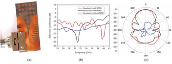
A wideband, high gain Vivaldi antenna was designed on a Rogers RT/duroid 5870 substrate ($\epsilon _r = 2.33$ , ${ h} = 0.254$
 mm, $\tan \delta = 0.0012$
 ) at 28 and 38 GHz resonant frequencies of size $15.5\times 32\, {\rm mm}^2$
 . The H-shaped metamaterial unit cell was employed in the radiating aperture of the antenna to enhance the aperture efficiency by correcting the phase in the complete operating frequency band. The gain achieved was 12.5 dBi with 78% aperture efficiency at 28 GHz resonant frequency. In addition, a stacked pattern diversity antenna module was also implemented which achieved wide-angle coverage of $-60$
 to $+ 60^\circ$
 with the beam directed at $0,\; + \!45$
 , and $-45^\circ$
 . The fabricated front view, $S$
 -parameters, and radiation patterns are shown in Figs 30(a), 30(b), and 30(c) [Reference Muzaffar, Magray, Karthikeya and Koul121].
Metamaterial-based Vivaldi 5G antenna: fabricated (a) front view, (b) $S$ -parameters, and (c) radiation patterns. [Reference Muzaffar, Magray, Karthikeya and Koul121].

Switched beam antenna as a smart antenna has been used in 5G antenna system as the implementation of it is simple and requires less cost as compared to phased antenna arrays. It consists of an antenna array and beamforming network such as Butler matrix, and hybrid line coupler. The $n \times n$ Butler matrix is used as a beamforming system and it generates the $n$
 -beams, which are linearly spaced phase difference at its output ports. The Butler matrix design is widely used due to its simple design and its ability to form orthogonal narrower beams which are highly directive and therefore the antenna has a low side lobe level [Reference Li, Chu, Lin and Chang122, Reference Rao123].
A $2\times 10$ antenna array excited by branch-line hybrid coupler was designed on a Rogers RT/duroid 6002 substrate ($\epsilon _r = 2.9$
 , ${ h} = 0.254$
 mm, $\tan \delta = 0.0037$
 ) of dimensions $79.42 \times 11.53\, {\rm mm}^2$
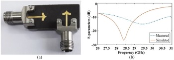
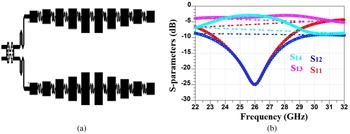
 in the operating band of 23.34–28.25 GHz. The gain reported was 14 dBi with a radiating efficiency of 83.82% at 26 GHz resonant frequency. The schematic view of the 2 $\times$
 10 antenna array, and $S$
 -parameters are shown in Figs 31(a) and 31(b) [Reference Moubadir, Mchbal, Touhami and Aghoutane124].
$2\times 10$ antenna array: schematic (a) front view and (b) $S$
 -parameters. [Reference Moubadir, Mchbal, Touhami and Aghoutane124].

The normalized array factors for a $4\times 4$ with a uniform excitation and a $4\times 8$
 Butler matrix are given by equations (38) and (39), respectively, [Reference Zhang and Hong125, Reference Prasad, Meenakshi, Adhithiya, Rao, Krishna Ganti and Bhaumik126]:


where $\psi$ =kdcos $\theta$
 + $\beta$
 .
Multibeam antenna arrays play an important role in 5G mm-wave communications. An array with a Butler matrix feeding network can generate multiple beams by feeding all the input ports active synchronously. There are many techniques that can generate fixed and multiple beams such as Blass matrix, Rotman lens, and dielectric lens. The field radiation pattern of the main beam can be modeled as equation (40):

where $N_{1}$ is the total number of elements in the array, $C_{n1}$
 are called the complex beam excitations, $( p,\; q)$
 represent points in space coordinate given by equation (41) [Reference Guenad, Meriah and Bendimerad127–Reference Ershadi, Keshtkar, Bayat, Abdelrahman and Xin129]:

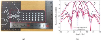
To obtain four multiple beams with high gains and reduced sidelobe levels a $4\times 7$ microstrip comb-line array excited and integrated with $4\times 4$
 Butler matrix (BM) was designed on a Taconic TLY-5 substrate ($\epsilon _r = 2.2$
 , ${ h} = 0.254$
 mm, $\tan \delta = 2.20$
 ) of dimensions $95\times 32\times 0.254\, {\rm mm}^3$
 , in the frequency band of 27.525–28.325 GHz. The two attenuators were added to reduce the sidelobe level and also to decrease the coupling between the input ports due to the standing waves from the antenna arrays; the three identical H-slots were employed on the ground plane as decoupling structures. The gain lies in 14.21–17.87 dBi and the four beams were generated by each of the excitation ports pointing toward the directions of $\pm 16.2$
 , $\pm 40.8$
 , $\pm 39.4$
 , and $\pm 12.6^\circ$
 . The fabricated front view of the butler matrix with antenna array and radiation patterns are shown in Figs 32(a) and 32(b) [Reference Trinh-Van, Lee, Yang, Lee and Hwang130].
5G $4\times 4$ antenna array with Butler matrix: fabricated (a) front view and (b) radiation patterns. [Reference Trinh-Van, Lee, Yang, Lee and Hwang130].

5G antenna designs in 60 GHz frequency bands
In this section, various designs of 5G antennas arrays, MIMO antennas, and MIMO antenna arrays, and beamforming antennas in frequency range 57–64 and 64–71 GHz frequency bands are discussed along with their designs and results.
The mm-wave band that lies in the 24–100 GHz frequency band which opens up the new dimensions and challenges for the 5G wireless communication systems. The unlicensed frequency band which lies in 57–61 GHz initiates a large bandwidth possibility for 5G mobile communication that will enhance 5G network capacity which can significantly boost the data rate. To cover the wide bandwidth and to overcome the atmospheric absorption that peaks at 60 GHz at 16 dB/km which requires a high gain antenna, can be accomplished by large antenna arrays. The dimensions of the antenna are given by equations (42) and (43), respectively [Reference Zhang, Ge, Li, Guizani and Zhang131, Reference Issa, Fathallah, Ashraf, Vettikalladi and Alshebeili132]:


where $M$ and $N$
 are non-negative integers, and $\lambda _{0}$
 and $\lambda$
 are free space and operating wavelengths, respectively.
The $\Delta L$ is the patch extension due to the fringing field effect. The dimensions of the microstrip feed lines can be measured by employing impedance transformation and the generalized equations are summarized in equations (44) and (45), respectively:


The $x$ is dependent on the substrate thickness ($h$
 ) and copper cladding ($t$
 ) can be defined by equation (46):

The spacing between the patch elements is defined by equation (47):

The inter-separation distance between the parallel arms are computed by equation (48):

where $A$ and $B$
 are the non-negative integers [Reference Jose, Radha, Sreeja, Alsath and Kumar133, Reference Rabbani and Ghafouri-Shiraz134].
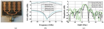
A high gain $4\times 6$ antenna array fed with series–parallel transmission lines was designed on a Rogers RT/duroid 5880 substrate ($\epsilon _r = 2.2$
 , ${ h} = 0.127$
 mm, $\tan \delta = 0.0009$
 ) with a size of $27.05\times 31.62\, {\rm mm}^2$
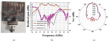
 for 60 GHz frequency band. In this design patches were excited by the two-stage power dividers and low impedance transmission lines were employed by reverse impedance matching method to achieve low power loss. The gain achieved was 19.26 dBi at 61.56 GHz resonant frequency. The fabricated front view, $S$
 -parameters, and radiation patterns are depicted in Figs 33(a), 33(b), and 33(c) [Reference Rabbani and Ghafouri-Shiraz135].
$4\times 6$ antenna array: fabricated (a) front view, (b) $S$
 -parameters, and (c) radiation patterns. [Reference Rabbani and Ghafouri-Shiraz135].

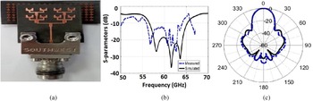
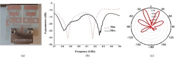
A compact and high-gain antenna array of eight-element was designed on a Rogers 5880 substrate ($\epsilon _r$ = 2.2, $\tan \delta = 0.0009$
 , ${ h} = 0.381$
 mm) with a size of $17.5\times 22\, {\rm mm}^2$
 in the operating frequency band of 56.5–65.2 GHz for mm-wave band applications. The patches were partially circularly slotted and the ground was defected with a circular-shaped slot, respectively to get the proper impedance matching. An EBG reflector consisting of $7 \times 17\, {\rm mm}^2$
 unit cells below the array structure was employed to decrease backward radiation and to improve the front-to-back (F/B) lobe radiation ratio. The gain achieved was 17 dBi with radiating efficiency of 97% at 60 GHz. The fabricated front view, $S$
 -parameters and radiation patterns are shown in Figs 34(a), 34(b), and 34(c) [Reference Ghattas, Saad and Khaled136].
Eight element antenna array: fabricated (a) front view, (b) $S$ -parameters, and (c) radiation patterns. [Reference Ghattas, Saad and Khaled136].

A high gain, mm-wave antenna array was designed on Rogers RT/duroid substrate ($\epsilon _r = 2.2$ , ${ h} = 0.254$
 mm, $\tan ( \delta ) = 0.0009$
 ) of dimensions $5.7\times 4.1\, {\rm mm}^2$
 operating at 60 GHz resonant frequency for mm-wave application. The concept of microstrip line discontinuities was utilized to enhance the performance parameters of the antenna such as gain and radiating efficiency. The left stubs and the right stubs along with square loops were tuned mutually to get proper impedance matching. The antenna gain and radiating efficiency reported were 17.5 dBi and 98% at 60 GHz resonant frequency. The fabricated front view, $S$
 -parameters, and radiation patterns are shown in Figs 35(a), 35(b), and 35(c) [Reference Al-Alem and Kishk137].
High gain antenna array: fabricated (a) front view, (b) $S$ -parameters, and (c) radiation patterns. [Reference Al-Alem and Kishk137].

A monopole antenna array was designed on a Rogers RO4003 substrate ($\epsilon _r = 3.55$ , ${ h} = 0.203$
 mm, $\tan ( \delta ) = 0.00027$
 ) with a size of $20.64\times 20\, {\rm mm}^2$
 for operating in 57.2–63.8 GHz frequency band. To improve the radiation characteristics, T-shaped slots and stubs were employed in the design. Also to enhance the bandwidth DGS was utilized. The gain of the antenna was 11.6 dBi with 85% radiating efficiency at 60.5 GHz resonant frequency. The antenna covered bandwidth from 57.2 to 63.8 GHz. The fabricated front view, $S$
 -parameters, and radiation patterns are shown in Figs 36(a), 36(b), and 36(c) [Reference Mneesy, Hamad, Zaki and Ali138].
Monopole T-shaped antenna array: fabricated (a) front view, (b) $S$ -parameters, and (c) radiation patterns. [Reference Mneesy, Hamad, Zaki and Ali138].

An MIMO antenna with different EBG structures was designed on a Rogers ULTRALAM substrate ($\epsilon _r = 2.9$ , ${ h} = 0.1$
 mm, $\tan \delta = 0.0025$
 ) of dimensions $13\times 14\, {\rm mm}^2$
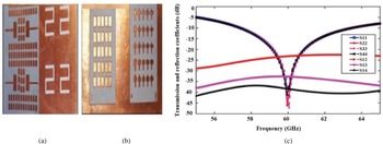
 for operating in 57–63 GHz frequency band. To decrease the mutual coupling between the antenna elements and to improve the radiation characteristics different EBG structures were employed. The gain and isolation reported were 14.8 dBi and 52.0 dB at 60 GHz resonant frequency, respectively. The fabricated front view, EBG view, $S$
 -parameters, and gain plot are shown in Figs 37(a), 37(b), and 37(c) [Reference Ullah, Yeo, Kim and Yoo139].
MIMO antenna with EBG: fabricated (a) front view, (b) EBG view, and (c) $S$ -parameters. [Reference Ullah, Yeo, Kim and Yoo139].

The small carrier wavelengths at mm-wave frequencies enable the synthesis of compact antenna arrays, providing beamforming gains that compensate for the increased propagation losses. mm-wave communication is a key technology for future wireless networks. To combat significant path loss and exploit the abundant mm-wave spectrum, effective beamforming is crucial. To overcome the severe link loss, a mm-wave array beamforming technology has been essentially adopted to the 60 GHz Wi-Fi system. The mm-wave beamforming technology enables the directional high gain in an array antenna, where the array antenna pattern can be electronically controlled to the desired direction. The high gain of the array antenna may compensate for the high signal attenuation. Moreover, the electric beam-location control can be utilized to search and find the best antenna pattern even upon the channel variation (e.g. human blockage). Therefore, beamforming technology plays a key role in maintaining the multi-gigabit data transfer link to enable the aforementioned 60 GHz Wi-Fi applications [Reference Horwath and Abhari140, Reference Aziz, Dahlback, Ojefors, Sjogren, Rydberg and Dancila141].
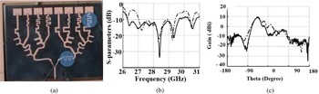
Switched-beam antenna array plays an important role in hybrid beamforming. A four-layer PCB stack structure was used to design a $2\times 10$ antenna array having the capability of generating three beams for a 60 GHz communication system. The $2\times 10$
 tapered antenna array was designed by employing a 1:0.91:0.74:0.54:0.38 Chebyshev tapering ratio on a Rogers RO4003 substrate ($\epsilon _r = 3.38$
 , ${ h} = 0.2$
 mm, $\tan ( \delta ) = 0.0027$
 ) for operating in 59.5–61.3 GHz frequency band. All the beams were switched and maximum gain was observed at $\theta$
 equals $0$
 , $-20$
 , and $20^\circ$
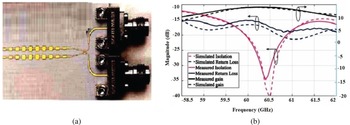
 . The gain was 12.93 dBi and the mutual coupling reported was >15 dB at 60 GHz resonant frequency. The fabricated front view and $S$
 -parameters are shown in Figs 38(a) and 38(b) [Reference Liu, Bshara, Tekin, Israel, Hoorfar, Taskin and Dandekar142].
$1\times 10$ antenna array: fabricated (a) front view and (b) $S$
 -parameters and gain plot. [Reference Liu, Bshara, Tekin, Israel, Hoorfar, Taskin and Dandekar142].

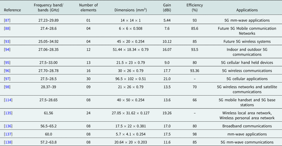
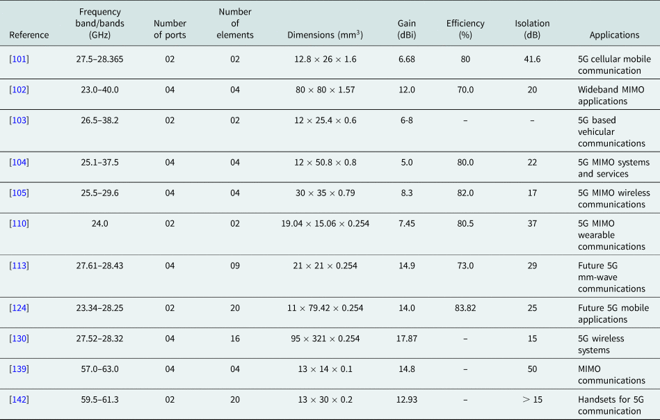
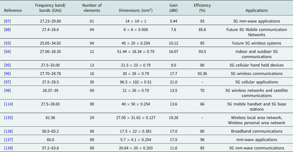
The comparison of 5G single port antennas and MIMO antennas for mm-wave frequency band lies in 28–40 and 54–71 GHz on the basis of different frequency bands, number of elements, gain, efficiency, dimensions along with their applications is presented in Tables 3 and 4.
Comparison of 5G one port 28–40 and 54–71 GHz antennas
Comparative analysis of 5G 28–40 and 54–71 GHz MIMO antennas

Conclusion
The 5G wireless communication is the demanding technology due to the tremendous growth of mobile data and extensive need for higher data rates, up to 1 Gbps. The use of recent technologies and techniques such as high gain antenna arrays, MIMO, massive MIMO, mm-wave communication, beamforming, etc., have been extensively used in 5G to enhance the data rates and lower the attenuation loss caused by the mm-wave frequency bands. In this paper, different 5G antennas such as single input ports, multiple input ports, single output ports, multiple output ports have been discussed. The different structures of mutual coupling reduction techniques between the antenna elements such as EBG, PBG, and DGS, were studied in paper. The main focus was to review, analyze, and compare different sub-6 GHz (2–8 GHz) antennas and mm-wave antennas (24–40, 57–64, and 64–71 GHz). The mentioned antenna designs in the paper have achieved >6 dBi gain with radiation efficiency around 80%, and isolation achieved was >20 dB. In addition with these designs, mathematical equations, and radiation characteristics have been discussed in detailin the paper.
 Mohit Pant received his M.E. degree in Digital Communication from the Institute of Engineering & Technology, DAVV, Indore, India in 2012 and his B.E. degree in Electronics and Communication from the Laxmi Narayan College of Technology, Bhopal (M.P.), India in 2004. Currently, he is working as an Associate Professor in the Mahakal Institute of Technology, Ujjain (M.P.), India and pursuing his Ph.D. degree from Shri G. S. Institute of Technology and Science, Indore, India. His current research interest includes millimeter-wave antennas, 5G antenna arrays for wireless applications, and multiple-input–multiple-output (MIMO) antennas for high data rate communications for 5G. He is a member of the IEEE. He holds a patent on ultra-wide-band (UWB) antenna design.
 Dr. Leeladhar Malviya received his Ph.D. from IIT Roorkee, India in 2017. He received his M.E. in Electronics and Telecommunication from Shri G. S. Institute of Technology and Science, Indore (M.P.), India, in 2008, and his B.E. in Electronics and Communication from the Government Engineering College, Ujjain (M.P.), India, in 1998. Since 2001, he has been with Shri G. S. Institute of Technology and Science, Indore (M.P.), India, and serving as an Associate Professor. His current research interests include compact multiple-input-multiple-output (MIMO) antennas for high data rate communications for 4G, 5G, and THz planar microstrip antennas, fractal antennas, and metamaterial antennas for communication. He is a Senior Member of IEEE, Fellow Institution of Electronics and Telecommunications Engineers (F-IETE, India), Institution of Engineers (IE, India), and Indian Society for Technical Education (ISTE). He is the reviewer of Elsevier, IEEE, IET, IETE-JR, IJCS, Engineering reports, and PIER journals. He has published a number of book chapters in Springer Singapore publication. He holds a patent on ultra-wide-band (UWB) antenna design. He is also the author of a book, “MIMO Antennas for Wireless Communication: Theory and Design” (CRC Press, 2020, Taylor and Francis).