I. INTRODUCTION
Nanofibers produced by electrospinning have attracted extensive attention because of their enormous potential in the diverse application areas.Reference Li and Xia1–Reference Fang, Niu, Lin and Wang3 They are often used in the forms of randomly oriented nonwoven fiber webs because of the easy production. However, nanofiber nonwovens are deficient in mechanical strength, which limits their application in areas such as bioscaffolds.
Yarns are typically interlocked fibrous bundles forming a basic building block to construct complicated fibrous architectures. The interlocked fibrous structure also assists in improving mechanical property. Indeed, efforts to produce nanofiber yarns directly from electrospinning process have been made over the years. By directly electrospinning nanofibers onto a water reservoir and subsequently withdrawing the freshly formed nanofiber web from the water surface, continuous nanofiber bundles have been prepared.Reference Smit, Buttner and Sanderson4 Without using liquid reservoir, continuous nanofiber bundles were prepared by combining nanofibers spun out of two electrospinning nozzles with opposite chargesReference Pan, Li, Hu and Cui5 or based on a self-bundling principle induced by a grounded needle.Reference Wang, Zhang, Zhu, Yu, Zhou, Chen and Hsiao6 Short and twisted nanofiber yarns were also prepared by collecting aligned nanofibers between two grounded parallel disks while rotating one of the disks to add twistReference Dalton, Klee and Moller7 or using a rotating metal hemisphere and a stationary metal rod as the collector.Reference Lotus, Bender, Evans, Ramsier, Reneker and Chase8 Recently, a novel electrospinning setup has been developed to directly produce highly twisted continuous nanofiber yarns from a rotating funnel where oppositely charged nanofibers were deposited.Reference Ali, Zhou, Wang and Lin9 Most of the works, however, focused on the preparation, morphology, and structure of nanofiber yarns. The mechanical properties and the influence of various parameters have been less investigated, despite the fact that mechanical property is essential for practical applications.
As with conventional yarns, fiber diameter, fiber uniformity, and yarn twist level have been known as important factors determining the mechanical properties. It is not yet clear how these factors affect the yarn mechanical properties when fiber diameter goes down to nanoscale. In this study, nanofiber yarns were fabricated by twisting a narrow fibrous strip cut from poly(vinylidene fluoride-co-hexafluoropropylene) (PVDF-HFP) electrospun nanofiber mat. The effects of fiber morphology, yarn twist level, and fiber alignment on the tensile properties of the nanofiber yarns were studied systematically. The reason for using this strip twisting method to make nanofiber yarns is because of the easy control toward twist level, fibrous orientation, and fiber uniformity.
II. EXPERIMENTAL
A. Materials and characterization
PVDF-HFP, N,N′-Dimethylformamide (DMF) and acetone were purchased from Sigma-Aldrich (Sydney, Australia) and used as received. PVDF-HFP solutions were prepared by dissolving the polymer pellets in a mixture solvent of DMF and acetone (1:1, v/v) and stirred overnight at room temperature.
Fiber and yarn morphologies were observed under a scanning electron microscopy (SEM; Zeiss Supra 55VP, Oberkochen, Germany). The average fiber diameter and fiber alignment degree were calculated based on SEM images using image processing software (Image Pro Plus 4.5). The acute angle between the surface nanofibers and the alignment direction was measured using image processing software (Image J 1.40) and used for calculating the angle deviation and alignment degree. At least 100 nanofibers were measured for above calculations. The yarn diameter was determined by a single fiber analyzer (SIFAN 2) with a CCD camera scanning at the resolution of 4 μm before tensile test. The mechanical property of the twisted nanofiber yarns was measured under standard conditions (20 ± 2 °C, 65 ± 2% RH) on a universal tensile tester (Lloyd LR30K, West Sussex, UK) with a 100 N load cell and a 10 mm/min crosshead speed. At least five samples were tested for each processing condition. The Fourier transform infrared (FTIR) spectra were recorded with a FTIR spectrophotometer (Bruker Optics, Ettlingen, Germany) in Attenuated Total Reflectance (ATR) mode.
B. Electrospinning
A purpose-made electrospinning setup was used for electrospinning.Reference Lin, Wang, Wang and Wang10 A homogeneous PVDF-HTP solution was transferred to a plastic syringe for electrospinning. A syringe needle (21G) was used as the spinning nozzle which was charged with a 16 kV voltage using a high voltage power supply (Gamma High Voltage, Ormond Beach, FL). The flow rate and the spinning distance were kept as 1 mL/h and 15 cm, respectively. The nanofiber mats with randomly oriented fibers were collected onto a stationary metal plate and aligned fiber mats were deposited onto a rotating metallic drum collector with the fiber taking-up speed ranging from 0.4 to 44.2 m/s.
C. Preparation of nanofiber yarns
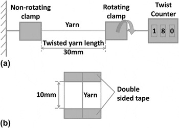
The nanofiber mats were cut into narrow strips and twisted into short nanofiber yarns. The apparatus for making nanofiber yarn is consisted of a nonrotating clamp, a rotating clamp, and a twist counter, as illustrated in Fig. 1(a). Narrow fiber strips (40 mm in length, 1mm in width) were sliced from nanofiber mats and twisted on the apparatus. Six different twist levels, 1000, 2000, 4000, 5000, 6000, and 8000 turns per meter (tpm), were used in this study. The yarns after twisting were fixed on plastic sheets using double-sided adhesive tape with a gauge length of 10 mm for mechanical testing [Fig. 1(b)].
Illustrations of (a) the laboratory-scale yarn twister and (b) twisted yarn sample fixed on a plastic sheet.

III. RESULTS AND DISCUSSION
A. Randomly oriented nanofiber mats
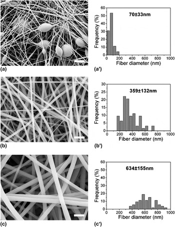
It has been previously reported that fiber morphology is a very important factor determining the mechanical properties of electrospun nanofibers.Reference Inai, Kotaki and Ramakrishna11 To understand the influence of fiber morphology on the mechanical properties of nanofiber yarn, PVDF-HFP nanofibers with different morphologies were prepared from the solutions of different PVDF-HFP concentrations (10, 16, and 20 wt%). The SEM images of the as-spun fibers are shown in Fig. 1. All these fibers were randomly oriented and the fiber morphology was highly dependent on the polymer concentration. Beaded fibers with an average diameter only 70 nm in the filament parts were obtained from the 10 wt% solution [Figs. 2(a) and 2(a′)]. The beads were in an oval or round shape with width between 1.7 and 3.3 μm. By increasing the polymer concentration to 16 wt%, nonbead uniform nanofibers were produced. Further increasing the polymer concentration led to increased fiber diameter with uniform fiber morphology maintained. When the polymer concentration was increased from 16 to 20 wt%, the average fiber diameter changed from 359 [Figs. 2(b) and 2(b′)] to 634 nm [Figs. 2(c) and 2(c′)].
Scanning electron microscopy (SEM) images and diameter distribution histograms of the poly(vinylidene fluoride-co-hexafluoropropylene) (PVDF-HFP) nanofibers electrospun from (a, a′) 10 wt%, (b, b′) 16 wt%, and (c, c′) 20 wt% solutions to a stationary metal collector, scale bar 2 μm.

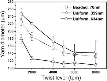
Nanofiber yarns were fabricated by twisting narrow strips cut from the randomly orientated nanofiber mats. Figure 3 shows the relationship between yarn diameter and twist level. The yarn diameter decreased with an increase in the twist level. When the twist level changed from 1000 to 4000 tpm, the yarn diameter decreased by 31, 34, and 30% for the yarns made of the beaded nanofibers, the uniform nanofibers of 359 nm diameter, and the uniform nanofibers of 634 nm diameter, respectively.
The relationship between yarn diameter and twist level.

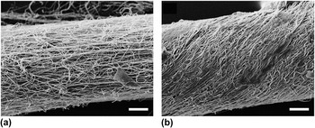
Figure 4 shows two SEM images representing the typical morphologies of the yarns twisted from the same nanofiber mat under different twist levels. The yarn with lower twist level [Fig. 4(a)] had a less compacted fibrous structure and a smaller surface twist angle compared to the one with higher twist [Fig. 4(b)]. This is because that the twist causes a lateral force on the fibers within the yarn. The fibers are therefore forced to form a closely packed structure. Once the yarn became closely packed, however, further increasing the fiber density became more difficult. As a result, the yarn diameter showed little changes when the twist level was high.
SEM images of (a) low-twist [1000 turns per meter (tpm)] and (b) high-twist (6000 tpm) nanofiber yarn. (Fiber diameter 356 ± 76 nm, scale bar 20 μm).

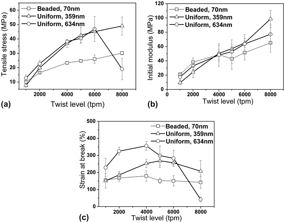
Figure 5 shows the effect of twist level on the tensile properties of nanofiber yarns. For the yarns made of the uniform fibers with an average diameter of 634 nm, the tensile strength increased initially with increasing the twist level until 6000 tpm and then decreased [Fig. 5(a)]. Such a trend is similar to the effect seen on conventional staple yarns, which can be explained by the two competitive effects: fiber–fiber cohesion and obliquity.Reference Hearle, Grosberg and Backer12, Reference Lord13 The tensile strength is originated from the overall fiber tension resisting the breakage along the yarn length direction. This is influenced by the fiber–fiber slippage and the orientation of fibers within yarns. Twisting adds transverse pressure to the yarn and meanwhile increases the fiber twist angle. At a low twist level, the steady increase in the yarn strength with the twist level was mainly attributed to the increased transverse pressure, which increases interfiber friction and reduces slippage. This makes it easier for loads to be transferred from one fiber to another, resulting in increased ability to withstand higher load and hence the increased maximum strength. However, the increased twist angle also decreased the component of fiber tension in the yarn length direction, resulting in reduced tensile strength. This effect became overwhelming when the twist level was higher than the optimum level, leading to the eventual decease in the tensile strength.
The influence of twist level on the tensile properties of nanofiber yarns.
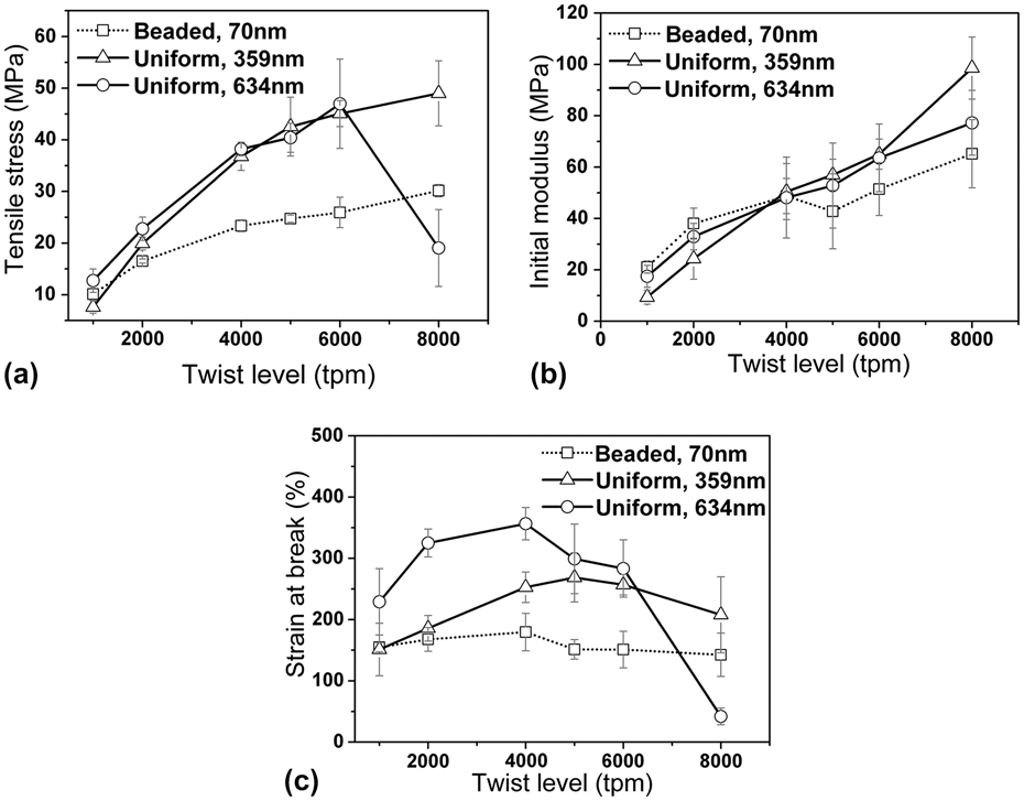
For the yarn made of finer uniform nanofibers (diameter 359 nm), the tensile increased by over 500% when the twist level was increased from 1000 to 8000 tpm [Fig. 5(a)], which was in a similar level to that of yarns made from coarser nanofibers (diameter 634 nm) except that the tensile strength did not drop over the whole twist level range studied. This suggests that reducing the fiber diameter could move the “obliquity effect” to a higher twist level. For the yarns made of beaded nanofibers, the tensile strength also showed no “obliquity effect” in the studied twist level range, however, the increase in the tensile strength was much lower than that of the yarn from 359 nm uniform nanofibers, indicating the considerable effect of fiber uniformity on the yarn tensile strength.
Higher twist level led to higher tensile modulus. All yarns showed almost the same trend except that a small deflection was found on the beaded nanofiber yarns at 5000 tpm twist level. When the twist level was lower than 4000 tpm, the modulus for the yarns made of uniform fibers was lower than that of the beaded nanofibers yarns. However, an opposite trend was observed when the twist level was higher than 4000 tpm. At 8000 tpm twist level, the yarns made of the uniform nanofibers (diameter 359 nm) showed the highest modulus (99 ± 12 MPa), which is followed by the yarns of uniform nanofibers with diameter 634 nm (77 ± 13 MPa). This is probably because finer nanofibers have strengthened interfiber contact thus generating higher frictional force.
The changes in the elongation at break looked more complicated. In most cases, the yarns twisted from the uniform nanofibers had higher elongation at break values than those from beaded fibers. With the increase in twist level, the elongation at break increased initially, but the value started decreasing after reaching a maximum level. The yarns made from the uniform nanofibers of diameter 634 nm had the maximum elongation at break of 367% at 4000 tpm, and the value then dropped sharply to 42% at 8000 tpm. Similar results were also obtained from yarns made of the 359 nm uniform nanofibers with a peak elongation at break of 268% at 5000 tpm. For the yarns made of the beaded nanofibers, the elongation at break changed little with the twist level. Since the twist introduced transverse pressure between the fibers, the initial increase in the elongation at break was attributed to the increased frictional force between the fibers, which delayed the occurrence of yarn rupture. When the yarn became highly compacted at a high twist level, the slippage of the fibers was considerably restricted. In this case, the yarn elongation was determined by the extension of the fibers mainly.
B. Aligned nanofiber mats
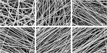
The effect of fiber alignment on the mechanical properties of twisted nanofiber yarns was also investigated. The aligned nanofiber mats were prepared using a high-speed metal drum as the collector. The degree of fiber alignment was controlled by the fiber take-up speed which can be adjusted through the rotating speed of the drum. As shown in Fig. 6, the collected fibers were still randomly orientated when the take-up speed was 0.4 m/s. The fiber alignment increased with increase in the take-up speed.
SEM images of the PVDF-HFP nanofibers collected at different take-up speeds (a) 0.4, (b) 5.6, (c) 11.2, (d) 22.4, (e) 33.2, and (f) 44.2 m/s, scale bar 2 μm.

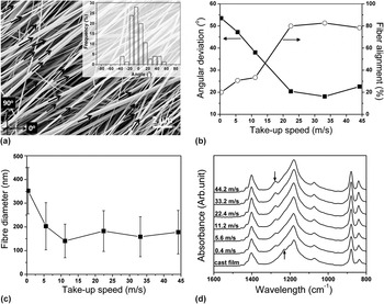
By measuring the acute angle formed between the nanofiber and a reference line in the SEM image, the degree of fiber alignment can be quantified. Figure 7(a) shows the measurement of a nanofiber alignment. The line 0° is the reference direction, based on which the acute angle between the fibers within the image and the reference line can be calculated. The average angle is the actual alignment direction diverging from the reference line, while the standard angular deviation (AD) can be used to measure the extent of the fibers deviating from the alignment direction. Assuming ±15° deviation from the average acute angle as the critical alignment range, the proportion of fibers fallen within this range can be used to describe the fiber alignment degree. Therefore, a highly aligned nanofiber mat should have a low AD and a large fiber alignment degree. Figure 7(b) shows the effect of collector take-up speed on the fiber alignment. With the increase in the take-up speed, the AD decreased while the alignment degree increased, suggesting the fiber alignment increased accordingly. However, the improvement in fiber alignment occurred only when the take-up speed was in the range between 0.4 and 22.4 m/s. The fiber alignment reached a plateau, around 80%, but the fiber alignment degree did not reach 100% even if higher take-up speed was used. This is probably because of air movement caused by the high-speed drum interfering with the fiber deposition.
(a) A typical SEM image for fiber angle measurement and the measured result, (b) the effect of collector take-up speed on the alignment degree and angular deviation, (c) fiber diameter as a function of take-up speed, and (d) Fourier transform infrared spectra of PVDF-HFP cast film and electrospun nanofibers collected at different take-up speeds.

The take-up speed was also found to influence the fiber diameter [Fig. 7(c)]. When the take-up speed was increased from 0.4 to 11.2 m/s, the average fiber diameter decreased from 359 to 141 nm. This is explained as that the jets at a higher take-up speed were subjected to a higher stretching force during collection. Further increase in the take-up speed did not result in any significant change in the average fiber diameter.
It has been reported previously that a high-speed rotating collector could change the orientation of polymer macromolecules and the crystalline phase within the electrospun fibers.Reference Bellan and Craighead14, Reference Catalani, Collins and Jaffe15 To verify the crystalline phase changes, the FTIR spectra of the nanofibers collected at different take-up speeds were measured. As shown in Fig. 7(d), β crystal phase was formed with the characteristic vibration peak at 1275 cm−1 in the nanofibers. However, very subtle difference was observed between the spectra of nanofiber samples collected at different take-up speeds, indicating the fiber crystalline morphology was not significantly affected by the take-up speed. It was interesting to note that β crystal phase was normally formed from α crystal phase through high ratio mechanical stretching. For the electrospun nanofibers, they contained β crystal phase even when the fiber collecting speed was very low. For comparison, the FTIR spectrum of the cast PVDF-HFP film was also included in Fig. 7(d). The cast film had a vibration peak at 1234 cm−1, which is the γ crystal phase, and the same peak was not found from the nanofiber samples.
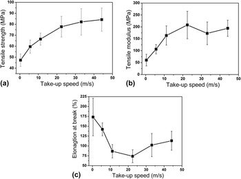
Figure 8 shows the tensile properties of the nanofiber yarns twisted from nanofiber mats collected at different take-up speeds. All strips were cut along the main fiber alignment direction. The yarn tensile strength gradually increased from 47 to 84 MPa. The tensile modulus had a similar increase with the increase in the take-up speed initially but exhibited fluctuation when the speed was higher than 22.4 m/s. Higher take-up speed enabled more fibers within the yarn to distribute the tensile loading during the test, thus, making a stronger yarn. As a result of the higher fiber alignment, the fiber slippage was less likely to happen and the elongation at break therefore decreased.
The effect of fiber take-up speed on the mechanical properties of nanofiber yarns. (Twist level 8000 turns per meter).

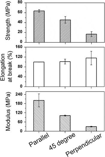
Fiber orientation within the twisted yarn was also an important parameter affecting the tensile property. Figure 9 shows the tensile property of nanofiber yarns twisted from strips cut in three directions (parallel, at 45° and perpendicular to the fiber alignment). The nanofiber mat was collected at 22.4 m/s take-up speed. Because the fiber alignment was along with the testing direction, the yarn twisted from parallel strips had higher tensile strength and tensile modulus than those of the yarns twisted from the strips cut in other directions. The difference in yarn elongation at break was relatively small.
The tensile properties of nanofiber yarns twisted from the strips cut at different directions (parallel, at 45° and perpendicular to the strip length direction).

IV. CONCLUSIONS
A strip twisting technique was used to prepare nanofiber yarns and the influences of fiber diameter, uniformity, alignment, and processing parameters on the yarn tensile properties were examined. For the yarns made from randomly oriented fine uniform nanofibers (e.g., diameter 359 nm) or beaded nanofibers, the tensile strength increased with an increase in the yarn twist level within the studied twist level range (1000–8000 tpm). Higher fiber diameter (e.g., 634 nm) led to the tensile strength having an initial increase and then decrease trend. The modulus increased with increasing the twist level for all the yarns studied. However, the elongation at break increased initially and subsequently decreased within twist levels examined. The fiber uniformity had a significant impact on the yarn mechanical property. At the same twist level, yarns made from beaded fibers had a lower tensile strength than those from uniform fibers. Fiber alignment was an important parameter affecting the yarn tensile properties. When the fiber alignment was in the length direction of nanofiber strip, both tensile strength and modulus increased with increasing the fiber alignment level, while the elongation at break changed very little. Although this study focused on short nanofiber yarns twisted from nanofiber mats, the conclusion drawn should apply for those prepared from other nanofiber yarn system, which will be verified in further work.
ACKNOWLEDGMENTS
Funding support from Australian Research Council under its Discovery grant scheme and from Deakin University under the Central Research Grant scheme is acknowledged.