Introduction
As a new type of artificial electromagnetic structure, metamaterial can effectively control electromagnetic waves by suitable periodic arrangement of microstructural metallic or dielectric inclusions. Its unique electromagnetic properties make it widely used in designing new-type antennas and improving the performance of conventional antennas [Reference Su and Chen1–Reference Lin and Chen5]. As one of its applications, the metamaterial lenses have been widely used to realize high-performance antenna, such as high-gain [Reference Lin and Wong6, Reference Li, Wang, Liang, Gao, Hou and Jia7], beam scanning [Reference Su and Chen8, Reference Jiang, Chen, Zhang, Hong and Xuan9], and beam splitting [Reference Katare, Chandravanshi, Biswas and Akhtar10]. As alternative to conventional dielectric lens, the metamaterial lens can control the refractive index of the unit cell to change arbitrarily in the aperture. Thus, metamaterial lens has shown its utility in designing a variety of microwave applications. However, the assembly and measurement process of this type of lens antenna are relatively complicated due to its three-dimensional structure.
In order to further reduce the overall size of the high-performance antenna and make the assembly process more convenient, some relevant researches have been emerged [Reference Li, Lu, Sang, Zhang and Lv11–Reference Yesilyurt and Turhan-Sayan21]. Antipodal tapered slot antenna (ATSA) has become a hot pot in the research of high-performance and low-profile antenna due to its planar structure, which makes it easy to integrate with lens. Adding metamaterial or dielectric covers on both sides of conventional ATSA is an effective method to design small-sized antennas with high directivity and gain [Reference Li, Lu, Sang, Zhang and Lv11, Reference Li, Zhou, Gao, Wang and Lv12]. This method can increase the realized gain and narrow the E-planes’ half-power beamwidth significantly. At the same time, planar lens can realize the excellent characteristics in two-dimensional plane, which reduces the space size of lens antenna [Reference Guo, Yang, Zhang and Deng13–Reference Yesilyurt and Turhan-Sayan21]. Generally speaking, the research studies about planar lens are mainly divided into two methods. On the one hand, electromagnetic waves focusing is realized by loading metamaterial unit cells with same size in the endfire direction of the ATSA, to improve the gain and reduce the beamwidth of E-plane [Reference Guo, Yang, Zhang and Deng13–Reference Sun, Chen and Qing15]. In [Reference Guo, Yang, Zhang and Deng13], Guo et al. realized a gain increment of about 2 dB in ultra-wideband by adding an artificial metamaterial lens with a planar structure in front of the feed antenna. On the other, the two-dimensional planar metamaterial lens which composed of unit cells with different refractive indexes have been widely investigated [Reference Pfeiffer and Grbic16–Reference Yesilyurt and Turhan-Sayan21]. This type of planar lens is more conducive to the integration with the feed antenna. In [Reference Pfeiffer and Grbic16], R. Singha et al. proposed a broadband gradient refractive index metamaterial lens to improve the gain and reduce to side lobe level of the ATSA, the gradient refractive index metamaterial is integrated in front of the ATSA to realize peak gain increment by 2.1 dB at 9.5 GHz. Omer Yesilyurt et al. designed an ultra-wideband metasurface lens which is integrated into an ATSA to improve its radiation directivity in [Reference Chen, Yang, Yang, Khin and Kehn17], this method realized a peak gain enhancement of about 4.5 dB over the frequency region of 1–6 GHz. Those research studies all have positive effect on radiation capability. However, some radiation parameters of the antenna still have room for further improvement.
In this paper, a planar metamaterial lens antenna which is fed by an ATSA with ultra-wideband and end-fire performance is designed. The planar lens which is constructed by using non-resonant unit cells with different refractive index to be placed in front of an ultra-wideband ATSA. With the planar lens loaded, the peak gain of the antenna reaches 15.4 dBi at 5.5 GHz, which increases 7.8 dB than the original ATSA. The simulated and measured results of the planar lens antenna show improvement in gain at the entire operating band.
This paper is organized as follows: the section ‘The design of planar lens’ introduces the specific structure of the unit cells and their distribution in planar lens. The section ‘ATSA with planar lens’ presents the structure and dimensions of ATSA. Then the performance of ATSA and the planar lens antenna is discussed. Finally, this paper is concluded in the last section.
Design of planar lens
Unit cell design
The spherical waves radiated by the feed antenna have different transmission paths when reaching different positions in space, the velocity of electromagnetic waves with shorter transmission paths in free space is slowed down by designing the unit cells to have higher refractive indexes. After the electromagnetic waves pass through the lens, the wavefront is flattened, thus improving the gain of the feed antenna. The metamaterial unit cell structure proposed in this paper is shown in Fig. 1. Two parallel metal lines are etched on both sides of the dielectric substrate FR4, respectively, whose relative permittivity and tangent loss are ɛ r = 4.3 and tan σ = 0.045, and the thickness is 1.52 mm. Additionally, the material of that four parallel metal lines are copper with a thickness of 0.0175 mm and conductivity of $\sigma {\rm} = 5.96 \times 10^7\,{\rm S/m}$ . The parallel metal lines whose width is 0.5 mm are connected at both ends of the metal lines through vias with diameter d = 0.5 mm. The dimensions of each unit cell are a = b = 15 mm, the distance between two adjacent parallel metal lines is p = 1 mm, and the length of each parallel metal lines is m. Meanwhile, the resonant metamaterial structure is accompanied by highly dispersive with considerable loss near the resonant frequencies, which is not suitable for applications where broad bandwidth and low loss are required. Therefore, the paper uses its electromagnetic characteristics in the non-resonant band to realize a smaller loss in the ultra-wideband.
Structures of the unit cell. (a) Top view, (b) front view, (c) simulation model.

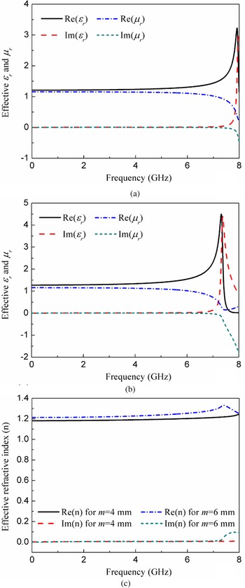
The effective parameters of the metamaterial unit cell include effective permittivity, effective permeability, effective refractive index and impedance, these parameters are extracted using the simulated S-parameters by the inversion method described in [Reference Szabo, Park, Hedge and Li22]. The effective permittivity and permeability of the unit cell always changes with the length of the parallel metal lines m, so that the refractive index of the unit cell changes correspondingly. The unit cells are retrieved to obtain their effective parameters, with m = 6 mm and m = 4 mm, respectively, and the results are shown in Fig. 2.
Effective parameters comparison diagram of the unit cells with different dimensions. (a) Effective permittivity and permeability of unit cell for m = 4 mm, (b) effective permittivity and permeability of unit cell unit cell for m = 6 mm, (c) effective refractive indexes of unit cells for m = 4 mm and m = 6 mm.

As can be seen from Fig. 2, with the different length of the parallel metal lines, the current path on the metal lines is also different, so the designed unit cell resonant frequency is also changing with the value of m (7.9 and 7.3 GHz respectively), thus affecting the stability of electromagnetic parameters in the non-resonant region. It can be clearly observed from Figs 2(a) and 2(b) that when the frequencies lower than resonant region, the real part of effective permittivity monotonically increases as frequency increases while the effective permeability are relatively uniform. Moreover, the imaginary parts of these two parameters are also near zero, which indicating that the designed unit cell have negligible electromagnetic loss and relatively weak dispersion. Similar results can also be seen from Fig. 2(c), the refractive index of each unit cell changes little with m in the whole operating band. Hence, the paper uses the designed unit cells working in their non-resonant region to achieve an effective control of the constitutive parameters in wider frequency band.
Design of planar lens
The optimized unit cells are formed into a cylindrical symmetrical lens as shown in Fig. 3. From the above analysis, it can be seen that the extracted effective refractive indexes are changes with the lengths of parallel metal lines in the unit cells, so differential refractive index can be realized by changing the lengths of parallel metal lines in the unit cell. The traditional gradient refractive index lens can greatly improve the radiation ability of the antenna, but the lens is placed vertically with the antenna, the three-dimensional size of the antenna is too large. Therefore, coplanar lens antenna is a better choice on some occasions with strict size requirements. In this paper, the coplanar lens is designed by using the design method of three-dimensional graded index lens. Generally, the refractive index distribution of unit cell in the lens is calculated according to the following modified formula:

where n 0 is the maximum refractive index of the unit working 5 GHz located at the center of the lens, y is the position of the unit in the lens, F is the distance from the feed source to the lens and T is the thickness. In addition, the working principle of planar lens in this paper can be explained by Snell's law. Figure 4 shows the path of the electromagnetic wave transmitting from equivalent medium i to medium i + 1. According to Snell's law, we have:

ni and ni +1 is respectively the refractive index of the different equivalent mediums. The refractive index of medium i is higher than medium i + 1, so αi +1 is larger than αi. It represents the electromagnetic wave propagating in the direction close to the center of the symmetry axis of the lens. Therefore, spherical waves can be transformed into plane waves by changing the values of ni and αi. In this paper, the planar lens is discretized into nine regions, where each region composed of unit cells corresponding to a specific refractive index, and the dimension of the planar lens is 270 mm × 255 mm. According to the above formulas, the refractive index of the unit decreases from the middle to the edge. Meanwhile, the dimensions and refractive index values of unit cells in planar lens are shown in Table 1 to explain the distribution.
Unit cells distribution in the planar lens.

Electromagnetic wave transmission path.

Dimensions of the unit cells and their effective refractive indexes in the different zones and incident angles of the planar lens

ATSA with planar lens
Feed antenna design
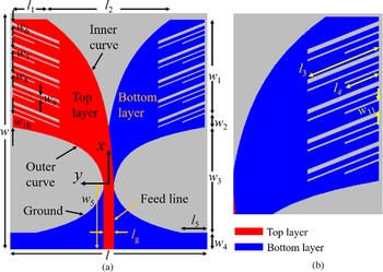
This paper chooses a broadband and high gain ATSA as the feed antenna, the geometry is shown in Fig. 5. In order to facilitate the integration of the feed antenna and planar lens, the FR4 which is the same as the substrate of the unit cell, is utilized for the design of the original ATSA. To obtain a symmetric radiation pattern, the metal radiation patches etched on both sides of the dielectric substrate are designed to have the same symmetrical structure. The ground and feedline are symmetrical in the xOy plane, respectively. To achieve good impedance matching with a 50 Ω SMA connector, the feed line width is designed to be 3 mm. In order to make the transition between the ground and the radiation patches smoother and avoid electromagnetic loss, the connection part is designed as an exponential curve structure. The two sides of the top and bottom radiation patches are designed into a sawtooth shape as shown in Fig. 5, this increases the flow path of the current on the patches, thereby extending the starting frequency to a lower one. Both sides of the radiation patches and the transition curve of the ground are comprised of an exponential function y = Ae αx + B, and the origin of coordinate is located 30 mm from the left side and 20 mm away from the lower side of the dielectric substrate. In this paper, the top metal is shown in red and the bottom metal is in blue. The parameters of the curves of patches and ground are listed in Table 2, and the other parameters are listed in Table 3.
Configuration of ATSA. (a) Schematic diagram of the original ATSA, (b) an enlarged view of the bottom radiation patch.

Equation and curvature parameters in Fig. 5

Design parameters of the ATSA (unit: mm)

Planar lens antenna design
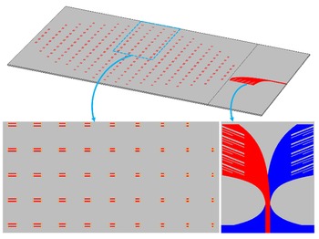
As shown in Fig. 6, the planar lens is placed in front of the ATSA to realize maximum electromagnetic wave focusing. The planar lens and ATSA are on the same horizontal plane, which can improve the performance and reduce the volume of the lens antenna as much as possible. At the same time, in order to simplify the processing and measurement process, the dielectric substrate on both sides of ATSA are extended laterally to make the lateral size the same as that of the planar lens. Simulation and measurement results show that the effect of this change can be ignored. Finally, the designed planar lens antenna is shown in Fig. 5.
Schematic of the planar lens antenna.

Simulation and experimental results
This section mainly introduces and analyses the performance of the proposed lens antenna. It mainly includes S-parameter, realized gain, radiation patterns and E-field distribution. The proposed ATSA and planar lens are manufactured by a high-solution printed circuit board technology to verify their performance. The S-parameters, radiation patterns and gain of the ATSA with or without planar lens are measured by a vector network analyzer ROHDE & SCHWARZ ZVH8 and standard gain horn antennas.
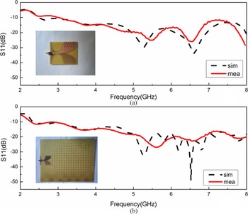
The simulated and measured reflection coefficients of the ATSA and assembled lens antenna are shown in Fig. 7. The results of ATSA are shown in Fig. 7(a), while that of the planar lens antenna are shown in Fig. 7(b), the experimental results of the two antennas are in good agreement with the simulation ones. It can be seen that the simulated −10 dB impedance bandwidth of the ATSA and planar lens antenna are from 2.41 to 8.00 GHz.
S-parameters (a) ATSA, (b) planar lens antenna.

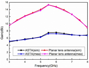
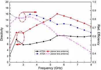
To further assess the performance of the proposed planar lens antenna, the realized gain of both ATSA and planar lens antenna are measured and compared with the simulated ones in Fig. 8. It can be observed that the gain of the ATSA can be significantly improved in the whole operating band by loading the planar lens. The gain of the planar lens antenna varies from 8.57 to 15.4 dBi. Compared with the ATSA which the gain varies from 4.93 to 7.58 dBi, the gain increases by an average of 6 dB in the entire working band. Due to the planar lens, the peak gain of the improved ATSA reaches 15.4 dBi at 5.5 GHz which increases about 7.8 dB. The simulated and measured −3 dB gain bandwidth of the planar lens antenna are 54.5% (4–7 GHz). Meanwhile, Fig. 9 shows the simulated radiation effectivity and directivity of ATSA and planar lens antenna. Due to FR4 is chosen for design in this paper, its efficiency is not high. But the directivity of planar lens antenna is higher than ATSA. In practical applications, low loss substrate (rogers, etc.) can be used, so that the directivity and radiation efficiency of the antenna can be considered.
Realized gain of the ATSA and planar lens antenna.

Simulated efficiency of ATSA and planar lens antenna.

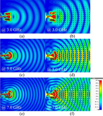
For another point of view, the gain enhancement mechanism can also be explained by the electric field distribution. The simulated electric field distribution on the E-plane (xOy plane) and the H-plane (xOz plane) at 3, 5, 7 GHz of the ATSA and planar lens antenna are depicted in Figs 10 and 11, respectively. It can be observed clearly from Fig. 10 that the wavefront of the planar lens antenna expanding more as compared to that of the ATSA in the E-plane. Since the middle part of the wavefront interacts most with the metallic inclusion and the refractive index of the unit cells in the center of the lens is higher than others which leads to a lowest phase velocity. Thus, the electromagnetic waves transmitted through difference positions in the lens have different propagation velocity, which can compensate for the path length difference between them. In Fig. 11, the wavefront flattening mechanism of the H-plane is the same as that of the E-plane. This extraordinary behavior of electromagnetic wave passing through the lens is mainly due to the interaction between the planar lens and the electromagnetic field. When the electromagnetic waves are incident upon the unit cells, the electromagnetic field excites the surface currents and then generates a strong local electric field between the unit cells. In fact, a large number of unit cells in the planar lens confine amount of power of the incident electromagnetic field between the metallic inclusions, so that the electromagnetic waves cannot radiate as spherically as it did in free space. This is the underlying reason for improving the performance of the ATSA through planar lens.
Two-dimensional E-field distribution plot for ATSA and planar lens antenna on the xOy plane (E-plane) at 3, 5, 7 GHz, respectively (a), (c), (e) ATSA, (b), (d), (f) planar lens antenna.

Two-dimensional E-field distribution plot for ATSA and planar lens antenna on the xOz plane (H-plane) at 3, 5, 7 GHz, respectively (a), (c), (e) ATSA, (b), (d), (f) planar lens antenna.

Besides, to analyze the radiation performance of the ATSA and planar lens antenna, the simulated and measured E- and H-plane are exhibited in Figs 12 and 13, respectively. As the designed ATSA and planar lens antenna have stable radiation patterns in the whole operating band, only 3, 5 and 7 GHz in the working band are selected for explanation, and the others are similar (not shown in this paper).
Simulated radiation patterns of ATSA and planar lens antenna considering antenna gain. E-plane at (a) 3, (b) 5, (c) 7. H-plane at (d) 3 GHz, (e) 5 GHz, (f) 7 GHz.

Measured radiation patterns of ATSA and planar lens antenna considering antenna gain. E-plane at (a) 3 GHz, (b) 5 GHz, (c) 7 GHz. H-plane at (d) 3 GHz, (e) 5 GHz, (f) 7 GHz.

To better compare the influence of planar lens on the ATSA, E- and H-planes of both antennas at same frequency are placed together. Figure 12 demonstrates the simulated radiation patterns with the consideration of antenna gain. It can be seen from the figure that the planar lens antenna has higher gain and directivity compared with the ATSA. At the same time, the half power beam width (HPBW) of the E- and H-plane is reduced effectively by loading the planar lens, which indicates that loading the designed planar lens can make the energy more concentrate. In addition, as can be seen that the ATSA and planar lens antenna have same cross polarization level, which indicates the planar lens has few effects on cross-polarization performance of ATSA.
Since the planar lens lies at the end of the flares of the ATSA as seen in Fig. 6, there are smaller portion of the wave is restricted and slowed down, to reduce the influence of metallic inclusions on the edges of the wavefront, which means the phase velocity of the field at the edge of the planar lens does not reduced by the same amount as the middle regions. In this case, the radiation patterns in the H-plane splits toward the end of the planar lens antenna. Fortunately, this spilt has a negligible effect on the HPBW of the antenna.
Table 4 illustrates the HPBW of ATSA and planar lens antenna on the E-plane and H-plane. As can be seen from the table and figure that the HPBW of E-plane and H-plane reduced significantly after loading the planar lens, which means that the radiation energy of planar lens antenna is more concentrated in the endfire direction compared with the ATSA. Thus, the planar lens antenna can achieve higher directivity and gain in the whole working band, which indicating that the planar lens has a positive influence on the performance of ATSA.
E/H-planes’ HPBW of ATSA and planar lens antenna

In order to have a better comparison between our results and other similar works, the size, operating band, peak gain increment and other performance are shown in Table 5. In this table, some parameters are estimated from the results in these references. It shows that the proposed planar lens antenna has a wider 3 dB impedance bandwidth which is equivalent to [Reference Li, Zhou, Gao, Wang and Lv12, Reference Singha and Vakula20, Reference Yesilyurt and Turhan-Sayan21]. Moreover, the proposed planar lens antenna has a higher peak gain and can achieve a larger gain increment. These performances ensure that the planar lens antenna can be suitable for ground penetrating radar and other applications which requiring high gain and ultra-wideband.
Performance comparison of the proposed planar lens antenna and similar works

Conclusion
An ultra-wideband, high gain, and low-profile planar lens antenna which is fed by a conventional ATSA is proposed in this paper. We adopt non-resonant metamaterial unit cells with different dimensions and refractive indexes to form the planar lens. The radiation gain and directivity of the ATSA are significantly improved by loading the single-layer planar lens in front of the ATSA. At the same time, the ultra-wideband characteristics of the original ATSA is maintained. Furthermore, the ATSA and the planar lens antenna are manufactured and measured. The measured results of the fabricated antenna show that the gain of the ATSA is increased in the entire operating band. Hence, the proposed antenna can be suitable for high gain and ultra-wideband applications such as short-pulse ground penetrating radar or microwave imaging systems.
Acknowledgements
This work was supported by the National Key Research and Development Program of China under Grant 2016YFC0600201 and 2018YFC0604104, the National Natural Science Foundation of China under Grant 41704176 and 41974092 and the Fundamental Research Funds for the Central Universities from China under Grant 2652019036.
 Ziye Wang was born in KaiFeng City, Henan Province, China in 1997. He received the B.E. degree in measurement and control technology and instrumentation from China University of Geosciences. Beijing, China in 2019. Currently he is a master student of University of Geosciences, Beijing. His main research interest includes phase array antenna, multibeam lens antenna, and reconfigurable metasurface.
 Zhengwei Yang was born in Tongren City, Guizhou Province, China in 1995. He received the B.E. degree in measurement and control technology and instrumentation from China University of Geosciences. Beijing, China in 2018. Currently he is a master student of University of Geosciences, Beijing. His main research interest includes the gain enhancement of broadband antenna, metasurface, and metamaterial lens.
 Xiao Zhao was born in Shandong Province, China in 1985. He received the B.S. degree in electronics and communication engineering from the Qingdao University in 2006, the M.S. degrees in electronics science from the Beihang University, Beijing, in 2009, and the Ph.D. degree in electronics science from the Tsinghua University, Beijing, in 2013. Since 2013, he has been an assistant professor with the Instrumentation Science and Technology Department, China University of Geosciences, Beijing, China. From 2017 to 2018, he was a visiting scholar with the College of Electrical Engineering & Computer Science, Oregon State University, OR, USA, and his advisor is professor Gabor C. Temes. He is currently an associate professor. He is the author of more than 15 articles and holds 9 patents. His research interests include low-power amplifier, low-noise instrumentation amplifier, high-precision sigma delta data converter, and high-efficiency low-dropout regulator.
 Linyan Guo was born in Yangcheng City, Shanxi Province, China in 1989. She received the B.E. degree in electronic information science and technology, in 2011. She also received the M.E. degree in electromagnetic field and microwave technology in 2013 and the Ph.D. degree in radio physics from Central China Normal University, Wuhan, China in 2016, respectively. Currently she is an associate professor of China University of Geosciences, Beijing. Her main research interest includes the theory and application of metamaterials, analysis and synthesis of antennas, and ground penetrating radar.
 Minjie Guo was born in Yangcheng City, Shanxi Province, China in 1995. He received the B.E. degree in mechatronic engineering, in 2018. Currently he is a master student of University of Geosciences, Beijing. His main research interest includes the enhanced gain of broadband antenna.