Introduction
Recently, the rapid advancement of network technology has caused an increasing demand for filtering antennas in wireless communication systems. These antennas are required to have wide bandwidth, compact designs, and stable gain performance. However, current filtering antennas still have limitations in these key performance aspects. Traditional filtering antennas typically include resonator, bandpass, bandstop, and waveguide filtering antennas, with filtering performance primarily relying on the integration of bandpass or bandstop filters within the feeding network as mentioned in Refs. [Reference Tu and He1–Reference Deng, Hou, Zhao and Guo4]. However, these additional components often increase the antenna design cost, and a narrower bandwidth in most cases, affecting their effectiveness in practical applications. There is an urgent need for a new filtering antenna design, which is crucial to meet modern wireless communication demands.
To overcome the narrowband limitation, antenna bandwidth is typically broadened by introducing parasitic structures and reflectors. As mentioned in Ref. [Reference Fan, Chen, Xu, Zhao, Feng and Yan5], a broadband compact dipole antenna is designed for the 5G frequency band, and a 50% impedance bandwidth is achieved by covering two dipole patches on different layers, however, the antenna design is intricate. A small-size, single-layer, broad-spectrum microstrip antenna with filtering capability is proposed in Ref. [Reference Yang, Zhai, Guo and Li6] , and parasitic patches are incorporated into the antenna design to expand bandwidth, and increase out-of-band suppression of high frequencies. In Ref. [Reference Liu, Hu, Su and Pan7], a circularly polarized wideband filtering antenna based on slot patches is proposed, the bandwidth of the antenna is enhanced by adding a patch as a reflector. In Ref. [Reference Chang, Chen, Zhang and Chen8], a parasitic element and two L-type arms are inserted to optimize impedance matching, so a wider bandwidth is achieved. However, the antennas mentioned in Refs. [Reference Yang, Zhai, Guo and Li6–Reference Chang, Chen, Zhang and Chen8] are relatively large in size. Magneto-electric dipole antennas, as mentioned in Refs. [Reference Yin, Wu, Yu, Wang and Hong9–Reference Hou, Ren, Liu, Cai, Wang and Yin11] , have a wide impedance bandwidth but a complex structure, accompanied by challenges such as electromagnetic interference and mutual coupling, special attention needs to be given to the optimization of the antenna structure, which increases the complexity of the design.
This paper presents a broadband, miniaturized, single-layer filtering antenna. A sawtooth Y-type filtering branch is introduced to create adjustable radiation nulls. Two rectangular metal cavities are introduced to balance the high-frequency current, and the cross-polarization level is reduced. To expand the bandwidth and improve out-of-band suppression, an arc-shaped slot isincorporated into the rectangular patch. The final design achieves an impedance bandwidth of 55%, out-of-band suppression greater than 25 dB at low frequency and 21 dB at high frequency. The cross-polarization level obtained in the xoz plane is lower than –35 dB. Additionally, the antenna demonstrates a high level of gain flatness.
Antenna design and optimization
Antenna configuration
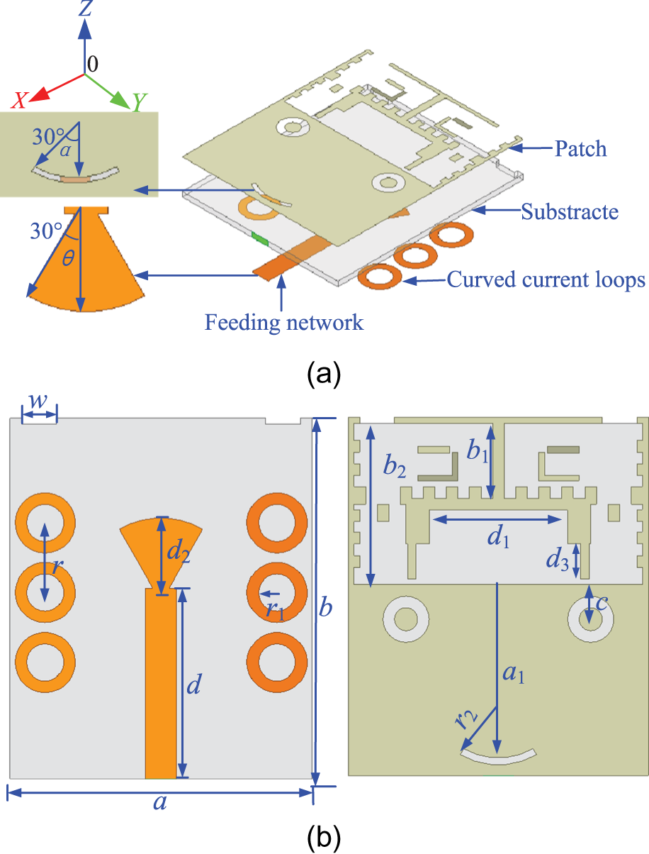
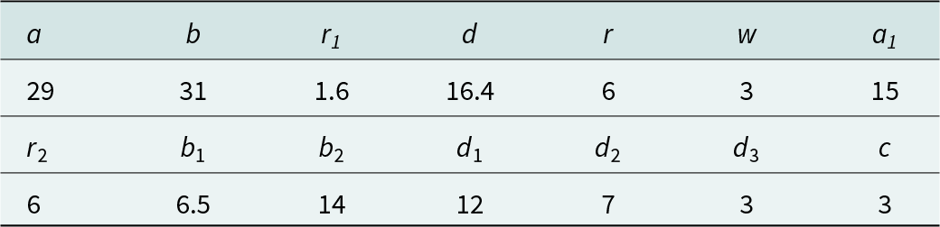
As shown in Fig. 1, the antenna uses an FR4 substrate with a thickness of 0.8 mm, a dielectric constant of 4.4, and a loss tangent of 0.02. A Y-shaped filtering branch is added to the radiation patch to create two radiation nulls. To expand the bandwidth and strengthen the out-of-band suppression of the antenna, the slot technique has been employed on the metal patch. Due to the introduction of the arc-shaped slot, a mid-resonant frequency is generated, which allows the antenna to attain broadband and high out-of-band suppression capability. At the same time, the impedance matching is improved by adjusting the dimension and central angle position of the arc-shaped slot. Two metal cavities are added above the rectangular slot, where the current is weak, which helps balance the current distribution. It led to a reduction in cross-polarization. These adjustments are crucial for achieving the desired filtering antenna. The antenna features a sector-shaped feeding network that exhibits wideband characteristics. Four sets of curved current loops are utilized to fine-tune the radiation nulls of the antenna. By integrating these design methods, the bandwidth of the antenna is expanded, an enhancement in frequency selectivity is realized, and a significant improvement in out-of-band suppression capability is attained. Table 1 displays the dimensions of the antenna.
The configuration of the proposed antenna. (a) 3D perspective, (b) top perspective, and (c) bottom perspective.

Dimensions of the proposed antenna (unit: mm)

Antenna design procedure
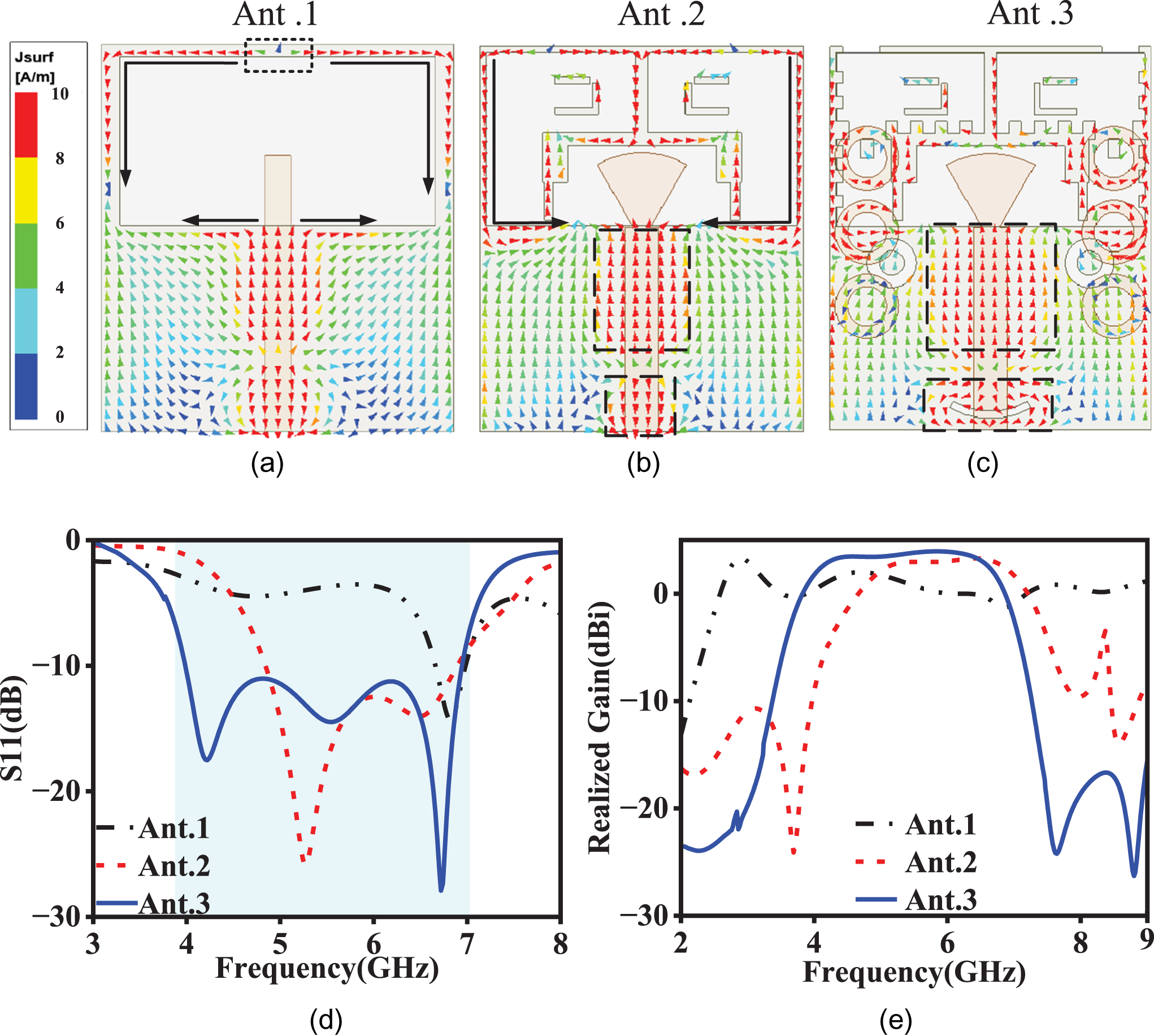
Figure 2 shows the variation of the current vector distribution, S11, and realized gain during the antenna design process. From Fig. 2(d), it can be observed that the peak of the S11 for Ant. 1 appears at 6 GHz, so Fig. 2(a–c) illustrates the changes in the current density vectors on the radiation patch at 6 GHz. From Fig. 2(d), it is evident that Ant. 1 lacks filtering capability. Therefore, a Y-shaped filtering branch is added above the rectangular slot, where there is a reverse current node, the reverse current path is increased to introduce additional radiation nulls, and part of the feeding network is modified into a sector shape to achieve wideband characteristics. From Fig. 2(b), the current on the Y-shaped filtering branch flows in opposite directions, and on both sides of the rectangular slot is significantly enhanced, resulting in improved radiation characteristics of the antenna. However, as observed from Fig. 2(e), the out-of-band suppression of Ant. 2 is poor at both ends of the passband, the filtering performance is suboptimal, and the passband gain is unstable. To enhance the filtering capability of the antenna, Ant. 3 incorporates curved current loops on both sides of the feeding network and beneath the rectangular slot, along with a sawtooth structure within the rectangular slot, extending and dispersing the strong current paths. An arc-shaped slot is introduced beneath the current node of the upper patch, the current distribution is strengthened, impedance matching is improved, and frequency selectivity is enhanced. It can be seen from Fig. 2(d) that the resonance frequencies are observed at 4.2, 5.5, and 6.7 GHz, with out-of-band suppression surpassing 25 and 21 dB at lower and higher frequencies.
(a) Current vector distribution of Ant. 1, (b) Ant. 2, (c) Ant. 3 at 6 GHz, (d) S11, and (e) realized gain.

Analysis of antenna performance
 \begin{equation}
f = \frac{1}{2\pi\sqrt{LC}} \tag{(1)}
\end{equation}
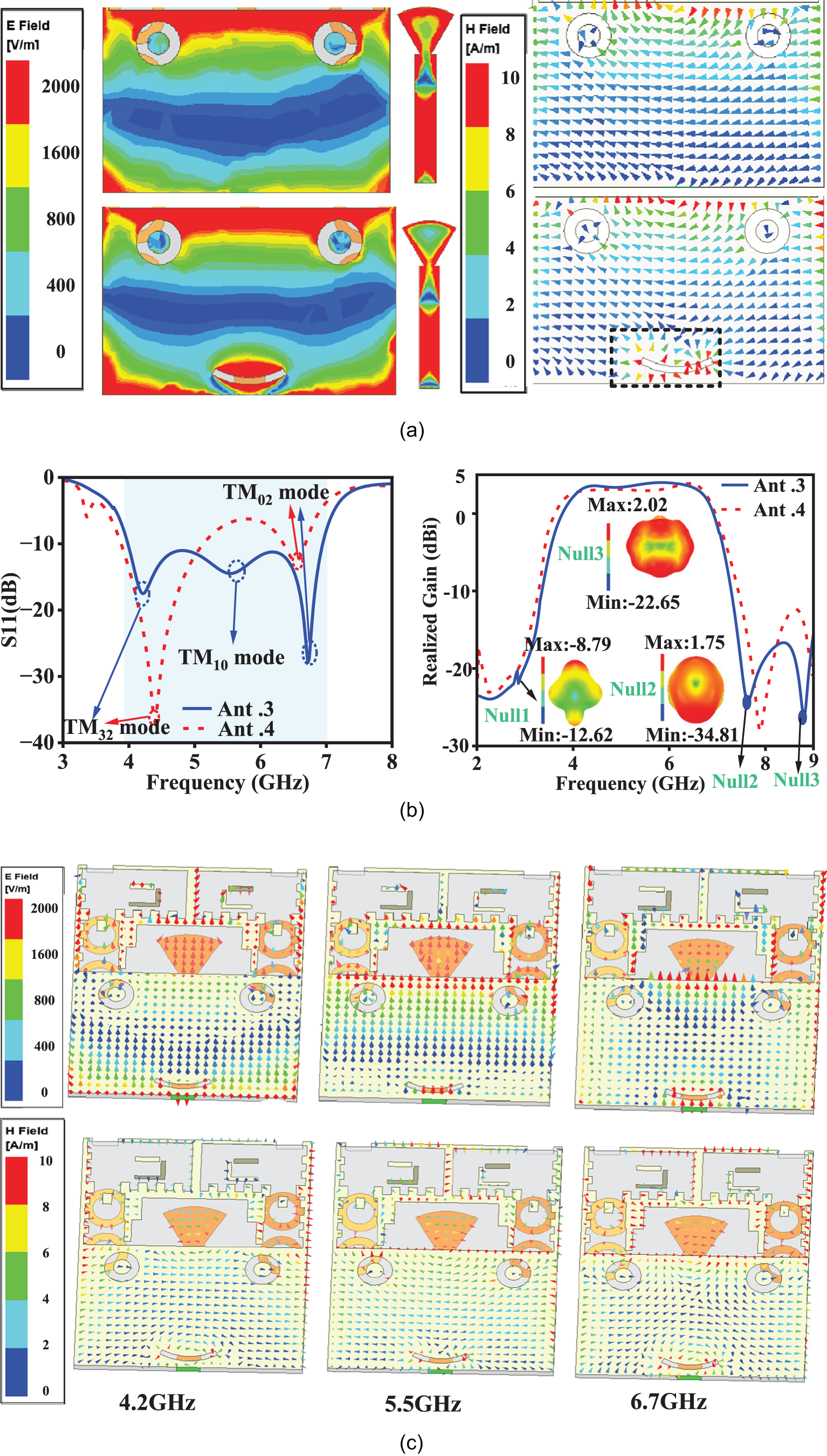
As shown in Fig. 3(a), the current distribution is guided, and the electromagnetic wave propagation path is changed by the addition of the arc-shaped slot. The slot structure creates strong localized electric and magnetic fields on the patch. Therefore, the arc-shaped slot forms a new resonant cavity, where the electric field accumulates charge around the slot, forming a capacitor. According to equation (1), when the capacitance increases, the resonant frequency shifts to a lower frequency. With the combined effect of capacitance and inductance, the antenna introduces a resonant frequency within the operating frequency range, S11 is shown in Fig. 3(b). As can be seen from Fig. 3(b), the inclusion of the arc-shaped slot introduces a new resonance mode at 5.5 GHz, and the bandwidth of the antenna is effectively broadened. The multiple resonance modes also increase the radiation efficiency and gain. The gain declines rapidly at the edge of the operating frequency band, and the frequency selectivity for the antenna is increased.
(a) The electric and magnetic fields at 6 GHz with and without the arc-shaped slot, (b) S11 and resonance modes, realized gain, and (c) the electric and magnetic field distributions at the three resonant frequencies of the antenna.

To better explain the formation of the resonant frequencies, Fig. 3(c) shows the electric field distributions at the three resonant frequencies. At 4.2 GHz, on both sides of the rectangular slot, strong electric and magnetic fields are formed, and a strong electric field is generated below the arc-shaped slot. In the width direction of the rectangular patch, three electric field nodes and one anti-node are observed. Meanwhile, in the length direction, two nodes and one anti-node are presented, indicating the excitation of the TM 32 mode. At 5.5 GHz, the number of electric field standing wave nodes decreases, with one node and one anti-node observed along the width direction of the rectangular patch. However, the field strength along the length direction remains almost unchanged, indicating the excitation of the TM 10 mode. At 6.7 GHz, the electric field around the rectangular slot and above the sector-shaped feeding network becomes weaker. Nevertheless, the electric field around the arc-shaped slot becomes intensified, and the TM 02 mode is excited.
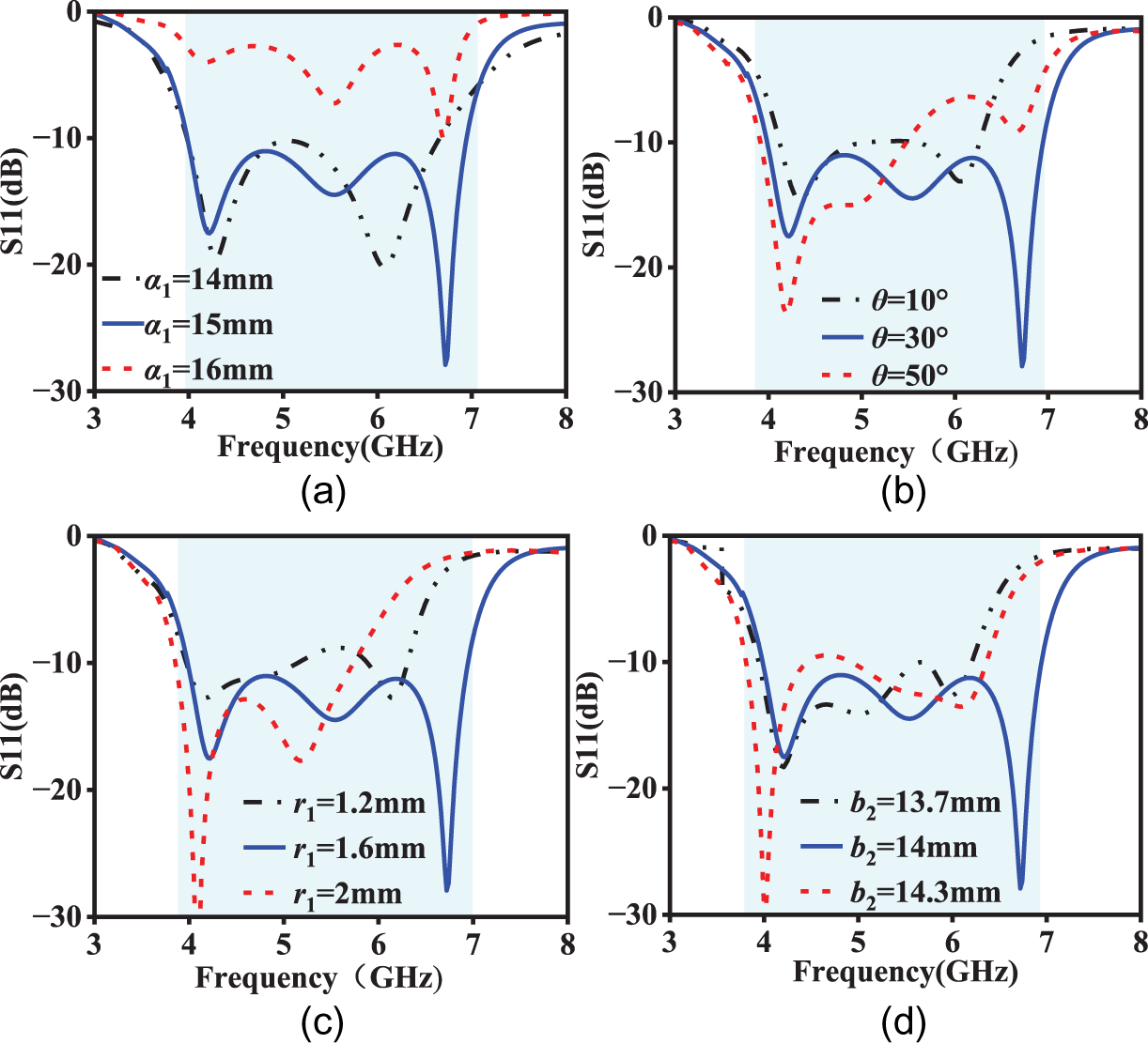
As shown in Fig. 4, increasing the values of parameters a 1 and θ causes the high-frequency resonance frequency to shift upward. This shift results in a decline in impedance matching performance and reduction in bandwidth. When r 1 and b 2 increase, the high-frequency resonant frequency first shifts to higher frequencies and then moves to lower frequencies, the impedance bandwidth first increases and then decreases. In contrast, the low-frequency resonant point remains almost unaffected, leading to a significant reduction in impedance bandwidth. It can be seen from Fig. 4 that the antenna achieved the optimal bandwidth at the present dimensions.
The impact of key parameters on S11. (a) a 1, (b) θ, (c) r 1, and (d) b 2.

The generation and reconstruction of radiation nulls
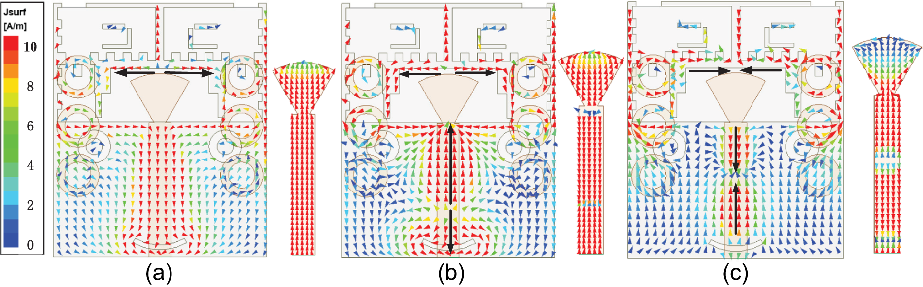
To explain the mechanism of the antenna radiation nulls, Fig. 5 illustrates the current vector diagrams of the designed antenna at 2.9, 7.6, and 8.8 GHz. As shown in Fig. 5(a), the current on the sawtooth arms diffuses in opposite directions to that of the main branch, as a result, a radiation null at 2.9 GHz is formed. At 7.6 GHz, the current on the sawtooth arms and above the rectangular slot diffuses in opposite directions. The combined effect of these two factors results in the first radiation null at high frequency. When the frequency reaches 8.8 GHz, the current on the sawtooth arms is weakened, while it is strengthened on both sides of the rectangular slot. At the same time, the current on the sawtooth arms and above the rectangular patch both converge from opposite directions, thereby a radiation null at 8.8 GHz is generated. This further enhances the filtering performance of the antenna.
Formation of radiation nulls. (a) Current distribution at 2.9 GHz, (b) current distribution at 7.6 GHz, and (c) current distribution at 8.8 GHz.

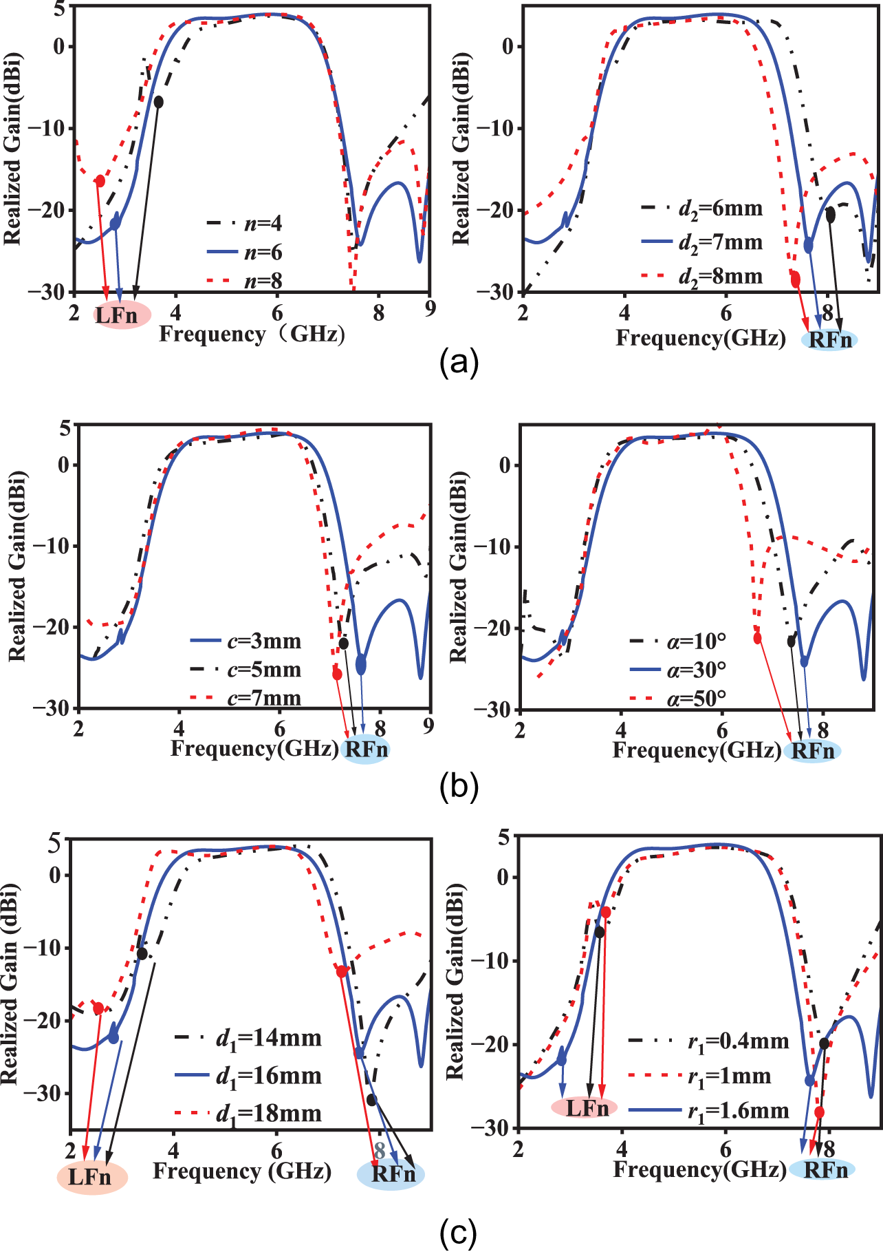
To further analyze the impact of antenna parameters on radiation nulls, Fig. 6 illustrates the variation of radiation nulls with the parameters n, d 2, c,  $ \alpha $, d 1 and r 1. The number of curved current loops at the bottom, denoted as n. As n increases, the current path of the antenna is extended, and the low-frequency radiation null is caused to shift toward lower frequencies. The angle
 $ \alpha $ in combination with the parameters d 2 and c plays a critical role in controlling the position of the high-frequency radiation null. Increasing d 2 affects the inductance of the feeding network, the high-frequency null being pushed toward the lower frequency. However, the low-frequency radiation null remains unchanged. The parameter c affects the electromagnetic coupling between the curved current loops and the rectangular slot. As c increases, the coupling mode can be modified, and the high-frequency radiation null shifts toward lower frequencies. The arc-shaped slot regulates the resonant point and high-frequency radiation null. When the angle of the arc-shaped slot is small, it has little effect on resonance, narrowing the gain bandwidth. When the angle increases, the current path is lengthened, and the resonant frequency is lowered. Thus, when the angle of the arc-shaped slot is 30∘, whether increased or decreased, causes high-frequency radiation to shift to lower frequencies. The combination of parameters d 2, c and
 $ \alpha $ can better control the high-frequency roll-off rate.
The adjustment parameters for the radiation nulls at high and low frequencies, as well as at both ends. (a) Parameter n and d 2, (b) parameter c and  $ \alpha $, and (c) parameter d 1 and r 1.

The high-frequency transmission null varies uniformly under the control of d 2, and a linear interpolation formula can be used to derive the variation pattern of the high-frequency radiation null:
 \begin{equation}
f_{d_2} = 10.4 - 0.4d_2 \tag{(2)}
\end{equation}
The above formulas reveal the key parameters that influence the radiation nulls at high frequencies. By adjusting the parameter, the antenna can achieve optimal performance across different operating frequencies.
In addition, the parameters d 1 and r 1 control the overall shift of the radiation nulls across the entire frequency band. The parameter d 1, which represents the distance between the two branches of the sawtooth arms, plays an important role in controlling the radiation nulls at both ends. As d 1 increases, the radiation null shifts to the left. When the radius of the curved current loops changes, it affects the current distribution of the feeding network and radiation patch of the antenna, which in turn affects the radiation pattern and the position of the radiation nulls.
Optimization of radiation performance
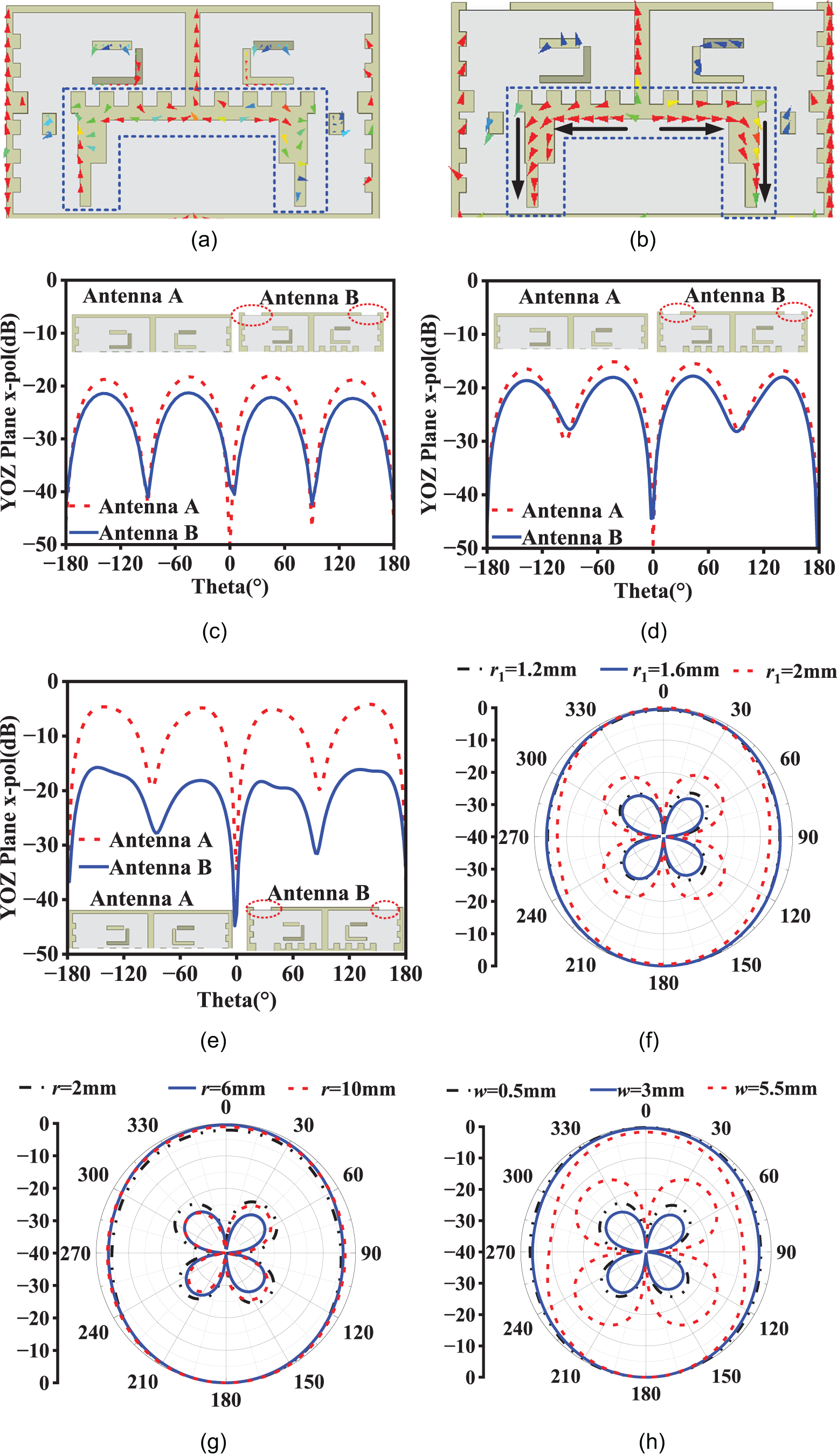
Since radiation performance is crucial for filtering antennas, this study employs high-frequency current balancing technology. Two rectangular metal cavities are etched above the rectangular slot, where the current is weaker, as shown in Fig. 7(b). This design suppresses certain electromagnetic modes and reduces cross-polarization excitation. It also minimizes irregular current flow and local current asymmetry, aiding in the balance of the radiation pattern. From Fig. 7(c–e), it can be seen that the addition of the rectangular metal cavities effectively lowers cross-polarization at the three resonant frequencies in the yoz plane, with a more pronounced effect on the high-frequency resonant mode. This improves the stability of the antenna at high frequencies.
Current distribution of different structures at 6.7 GHz and the cross-polarization at the resonance frequencies, the effect of different parameters on the polarization level at 4.2 GHz. (a) and (b) With or without rectangular metal cavities, (c) 4.2 GHz, (d) 5.5 GHz, (e) 6.7 GHz, (f) parameter r 1, (g) parameter r, and (h) parameter w.

To further improve polarization purity, Fig. 7(f–h) shows the impact of different parameters on the radiation modes. It can be observed that the radius and center distance of the curved current loops at the bottom of the substrate, as well as the size of the rectangular metal cavities, are the main factors influencing cross-polarization levels. When the radius and center distance are increased or decreased, both of these lead to uneven current distribution. As the rectangular metal cavities increase in size, the current stability of the main radiation filtering structure of the antenna is affected. However, as the cavity size decreases, insufficient current balance also affects the radiation pattern. These factors led to an increase in the cross-polarization level decreases. When r 1 = 1.6 mm, r = 6 mm, and w = 3 mm, the antenna exhibits the best radiation performance.
Results and discussion
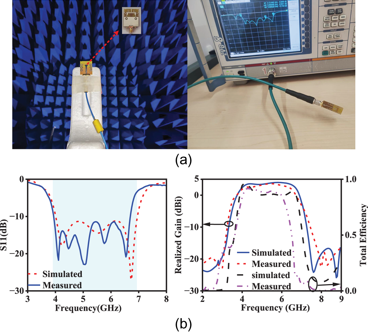
To verify the effectiveness of the design method, the antenna is fabricated and tested. Figure 8 shows the test environment and the measurement results of the antenna. The test data show that the measured results are relatively consistent with the simulation. However, manufacturing tolerances, installation inaccuracies, and unoptimal test conditions caused a leftward shift in the high-frequency resonance point of the antenna. The measured impedance bandwidth of the antenna is approximately 55%, with a stable gain of around 4.5 ± 0.3 dBi.
(a) Testing environment of the proposed antenna and (b) comparison of fabrication and testing results.

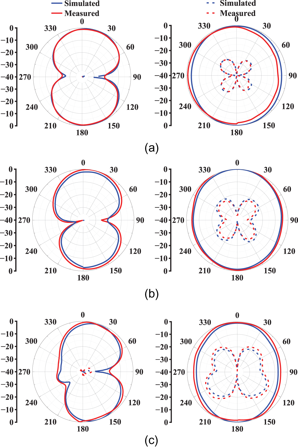
Figure 9 illustrates the radiation patterns of the antenna in the xoz plane and the yoz plane. The measured data demonstrates strong consistency with the simulated data. In the xoz plane, the cross-polarization is below –35 dB. At the 0∘ direction, the cross-polarization level is more than 32 dB lower than the co-polarization. At frequencies of 4.2 and 5.5 GHz, the cross-polarization electric field is more than 25 dB lower than the co-polarization field in the yoz plane. At 6.7 GHz, the cross-polarization level is less than –15 dB in the yoz plane. The antenna exhibits better stability at low frequencies.
Simulated and measured radiation patterns of the antenna at different frequencies. (a) At 4.2 GHz, (b) at 5.5GHz, and (c) at 6.7 GHz.

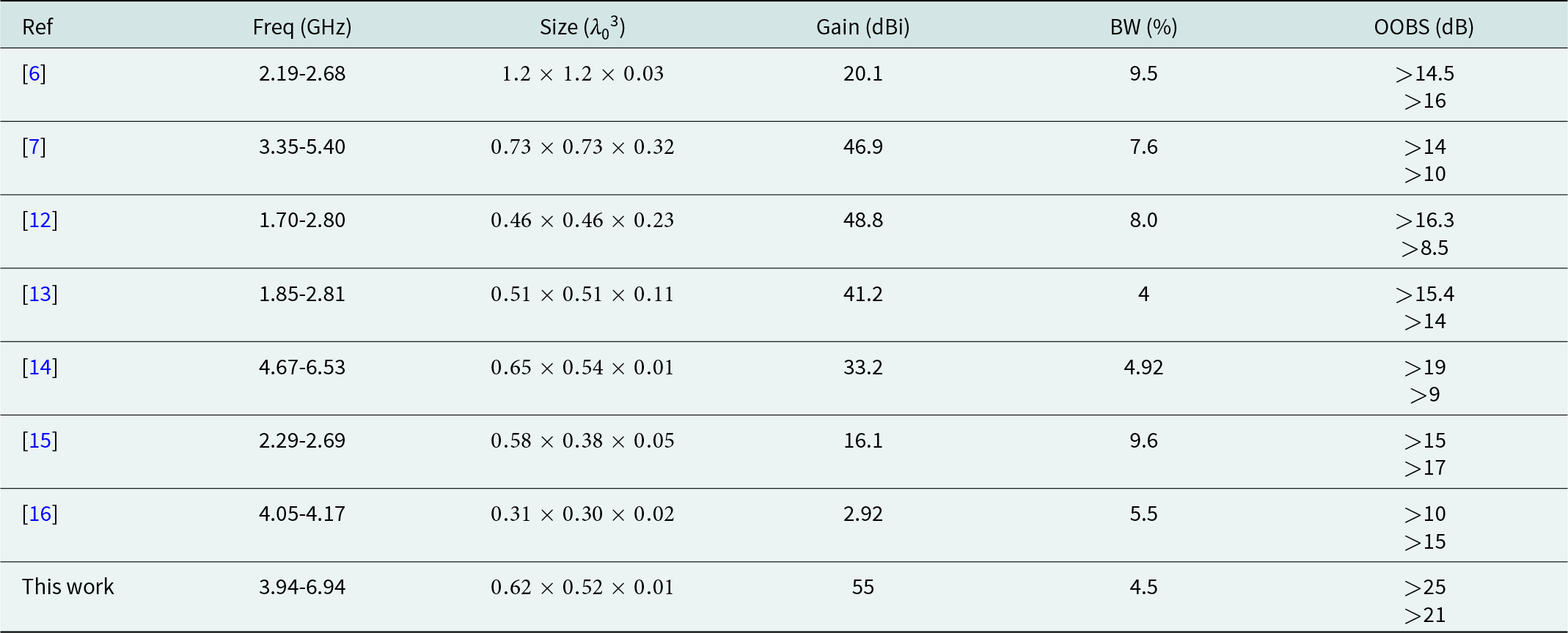
Table 2 presents a comparison of the designed antenna with similar band antennas from other literature. According to the table, the antenna designed in this study exhibits significant advantages in several aspects. First, it has a wide frequency range (3.94–6.94 GHz), covering multiple bands and offering broader application possibilities. Second, the bandwidth of the antenna is much higher than the designs in other references. Additionally, this design of study demonstrates high stability within the frequency range. Most importantly, the antenna designed in this study performs excellently in terms of out-of-band suppression (OOBS), reaching 21 dB, showing better frequency selectivity, and the ability to suppress unwanted radiation signals. Therefore, the antenna in this study has clear advantages in bandwidth, gain stability, and out-of-band suppression.
Comparison of the designed antenna with similar band antennas from other literature

λ 0 represents the free-space wavelength at the center frequency within the operating frequency band; OOBS represents out-of-band suppression.
Conclusion
A low-profile, wideband filtering antenna that employs a parasitic slot structure is presented in this paper. The antenna meets the design requirements for low cost and miniaturization, eliminating the need for additional filters, and achieves a compact size of only  $0.62\lambda_0 \times 0.52\lambda_0 \times 0.012\lambda_0$. By adopting the Y-shaped branch reverse diversion technique, the antenna achieves the filtering characteristic. At the same time, curved current loops, sawtooth structures, and a broadband sector-shaped feeding network are used, which significantly enhances the antenna’s out-of-band suppression capability. The parasitic arc-shaped slot tuning technology further increases the current density in a specific area, exciting new resonant frequency within the passband. This approach significantly broadens the bandwidth and enhances its frequency selectivity of the antenna. Using high-frequency current balancing technology, two metal rectangular cavities are etched above the rectangular slot to balance the current on the main radiation structure, thereby reducing the level of cross-polarization. The linear interpolation formulas summarized in this paper enable precise control over the high-frequency radiation nulls, allowing the antenna to maintain optimal performance across various operating frequency bands. This demonstrates excellent bandwidth extension and frequency tuning capabilities.
Acknowledgements
This paper is supported by Yunnan Fundamental Research project [202401AT070351, 202401AT070376, 202301AV070003], Yunnan Key Laboratory of Computer Technologies Application Open Fund, the Natural Science Foundation of China [61971208], Yunnan Young Top Talents of Ten Thousands Plan [Shen Tao, Yunren Social Development No. 2018 73], College personnel training project [202101BE070001-008], and partially by the Major Science and Technology Projects in Yunnan Province under Grant [202302AG050009 and 202202AD080013].
Competing interests
The authors declare that they have no conflict of interest or competing interests in relation to this work.

Jiangling Dou was born in 1985 in Jiangsu Province, China. She received her Ph.D. degree in Electromagnetic Fields and Microwave Technology from Southeast University in 2018. She is currently working at Kunming University of Science and Technology. Her research interests include electromagnetic field theory and applications.

Yinsu Yuan was born in 1997 in Qujing, Yunnan, China. She is currently pursuing a master’s degree at Kunming University of Science and Technology, focusing on the design of miniaturized filtering antennas.

Yujie Chen is currently pursuing a graduate degree at the School of Information Engineering and Automation, Kunming University of Science and Technology.

Peiyao Chen is currently pursuing a graduate degree at Kunming University of Science and Technology. Her professional research direction is antenna design, working on dipole antennas now.

Tao Shen (Senior Member, IEEE) earned his Ph.D. from the Illinois Institute of Technology in Chicago, Illinois, USA, in 2013. Presently, he holds the position of President at Yunnan Vocational and Technical College of Mechanical and Electrical Engineering. Dr. Shen has contributed to over 20 publications in prestigious SCIE-indexed journals and leading international conferences within his research domains. His areas of expertise include image processing, artificial intelligence, and the Internet of Energy.

Jian Song (Member, IEEE) obtained his Bachelor of Engineering degree in Electronics Information Engineering from Jiangxi University of Science and Technology in Ganzhou, China. He later earned his Ph.D. in Electromagnetic Fields and Microwave Technology from the University of Electronic Science and Technology of China in Chengdu in 2015. Between 2015 and 2019, he served as an Algorithm Engineer at Huawei Technology Co., Ltd. in Shenzhen, China. In 2019, he became a faculty member at Kunming University of Science and Technology. His research focuses on microwave engineering and the processing of biomedical images.