I. INTRODUCTION
Selective area doping of silicon carbide (SiC) by ion implantation is still the preferred technology for the fabrication of heavily doped n- and p-type regions in SiC electronic devices to reduce the specific resistance of a metal contact. Moreover, the more elevated doping values achievable by ion implantation with respect to epitaxial growth might favor the carrier emitter efficiency in bipolar devices under heavy current injection. The atomic solid solubility of dopant species in a SiC lattice sets the upper limit for the incorporation of such a species in SiC as an electrical dopant. N-type and p-type dopant solubility in SiC has been established in epitaxial material and these values constitute the upper boundaries, which need to be reached or overpassed to further increase the active doping concentration in the case of ion-implanted SiC materials. To obtain this, both the implanted dopant concentration per unit volume, as well as the temperature of the mandatory postimplantation annealing process for the recovery of the ion-damaged SiC lattice and the electrical activation of the implanted species, have been increased over the years.
The most used n-type dopants in SiC are nitrogen (N) and phosphorus (P). N and P occupy closely spaced levels in the 4H-SiC band gap, with N slightly deeper than P.Reference Ivanov, Henry and Janzén1 Unfortunately, there exists a discrepancy between experimental values regarding the solid solubility of N and P in epitaxial SiC materials, whereas in the case of ion-implanted SiC the published results agree on the fact that N electrical activation saturates at lower concentrations than P.Reference Capano, Cooper, Melloch, Saxler and Mitchel2, Reference Laube, Schmid, Pensl, Wagner, Linnarsson and Maier3 In particular, for 4H-SiC the electrical activation of N has shown saturation for implanted concentration of 3 × 10¹⁹ /cm3 and postimplantation annealing temperature of 1700 °C,Reference Laube, Schmid, Pensl, Wagner, Linnarsson and Maier3 whereas electrical activation of P has shown saturation for implanted concentration between 1 × 10²⁰ /cm3 and 4 × 10²⁰ /cm3 with postimplantation temperatures equal to, or above 1950 °C.Reference Nipoti, Nath, Qadri, Tian, Albonetti, Carnera and Rao4 The published N and P concentration values for electrical saturation in implanted 4H-SiC almost match with the theoretically predicted values for solid solubility of N and P in 4H-SiC lattice.Reference Bockstedte, Mattausch and Pankratov5 The saturation of the n-type resistivity for P-implanted 4H-SiC is in the low 10−3Ω cm region.Reference Nipoti, Nath, Qadri, Tian, Albonetti, Carnera and Rao4, Reference Negoro, Katsumoto, Kimoto and Matsunami6
The situation for the p-type doping of SiC is very different. Aluminum (Al) and boron (B) are the most commonly used species for the p-type doping of SiC by ion implantation. Generally, Al is preferred compared with B, even though Al produces more disorder in the SiC lattice due to its higher mass. The main reasons for the popularity of Al are that it has shallower ionization levels and does not diffuse during postimplantation annealing.Reference Negoro, Kimoto, Matsunami, Schmid and Pensl7, Reference Sundaresan, Rao, Tian, Ridgway, Schreifels and Kopanski8 Over the years the most common recipe for obtaining lower and lower material resistivity for p-type Al-implanted 4H-SiC has been to increase the implanted Al concentration per unit volume and to increase the temperature of the postimplantation annealing, the former up to the low 1021 /cm3 region and the latter up to 1800 °C.Reference Negoro, Kimoto, Matsunami, Schmid and Pensl7, Reference Bluet, Pernot, Camassel, Contreras, Robert, Michaud and Billon9 Very recently a minimum p-type 4H-SiC material resistivity in the low 10−2 Ω cm range has been obtained for an implanted Al concentration of 8 × 10²⁰ /cm3 and a postimplantation annealing temperature ≥2000 °C.Reference Nipoti, Nath, Rao, Hallén, Carnera and Tian10 This very promising result has been obtained by using a microwave furnaceReference Tian11 and it would be highly interesting to reproduce these results by annealing in a conventional heating system. The solid solubility of Al in epitaxial SiC has been measured and a limit of 2 × 10²⁰ /cm3 has been found at about 2000 °C.Reference Linnarsson, Janson, Zimmermann, Svensson, Persson, Hultman, Wong-Leung, Karlsson, Schöner, Bleichner and Olsson12 This article presents the first results of 1950 °C postimplantation annealing experiments that have been performed in an inductively heated furnace on Al+ implanted 4H-SiC with Al concentration in the range of 1 × 10¹⁹ to 8 × 10²⁰ /cm3.
II. EXPERIMENTAL
High-purity semi-insulating (HPSI) 4H-SiC wafers Si-face 8° miss-cut from the <0001> axis purchased from CREE Research Inc. (Durham, NC) have been used in this study. An HPSI SiC material has been used for avoiding interactions between implanted dopant and other impurities and for a better electrical isolation of the implanted layer during electrical characterizations. These wafers have been Al-implanted at 400 °C to obtain almost flat box profiles with Al concentrations of 1 × 10¹⁹, 5 × 10¹⁹, 1 × 10²⁰, 4 × 10²⁰, and 8 × 10²⁰ /cm3 over 330 nm. The Al depth profiles in as-implanted samples have been measured by secondary ion mass spectrometry (SIMS) and the data are published in Ref. Reference Nipoti, Nath, Rao, Hallén, Carnera and Tian10. The full width at half maximum (FWHM) of each box profile is about 390 nm, as measured by SIMS. This value has been taken as the effective thickness of the implanted Al box profile.
The as-implanted surface of each SiC sample has been covered with a pyrolyzed photoresist film (C-cap) using the receipt published in Ref. Reference Nipoti, Mancarella, Moscatelli, Rizzoli, Zampolli and Ferri13. In previous studies this type of C-cap was used for the postimplantation annealing of heavy dose P+ implanted 4H-SiC up to 1950 °C for 5 min and 2000 °C for 30 s.Reference Nipoti, Nath, Qadri, Tian, Albonetti, Carnera and Rao4 On these samples the root-mean-square (rms) surface roughness of both C-cap and underlying SiC after C-cap etching were measured by AFM: the former was smoother than the latter, and the latter increased for increasing P+ dose up to 8 × 10²⁰ /cm3 till a maximum rms roughness of 1.5 nm.Reference Nipoti, Nath, Qadri, Tian, Albonetti, Carnera and Rao4 In this study the rms surface roughness of the sample implanted at the highest Al dose of 4 × 10²⁰ /cm3 has been measured and found equal to (3.1 ± 0.5) nm.
Each capped SiC sample has been cut in pieces of 5 × 5 mm2, which have then been annealed in a high purity argon (Ar) atmosphere with a pressure ≥1 atm inside an inductively heated glassy carbon-coated graphite crucible. Annealing temperature, annealing time, heating and cool down conditions have been 1950 °C, 5 min, 40 °C/s, exponential with a decay time of about 3 min, respectively. After the postimplantation annealing, the C-cap has been removed by a thermal treatment at 850 °C in dry O2 for 10 min and Ti-Al ohmic contacts have been fabricated on the four corners of the square samples by using a previously published recipe.Reference Nipoti, Moscatelli, Scorzoni, Poggi, Cardinali, Lazar, Raynaud, Planson, Locatelli, Chante, Saddow, Larkin, Saks and Schoener14 These Van der Pauw (VdP) devices have then been used for sheet resistance and Hall effect measurements in the temperature range of 140–720 K. Taking into account the fact that the size of each VdP contact is not negligible with respect to the VdP device size, correction factors have been computed for both sheet resistance and Hall coefficient values, as suggested in Ref. Reference Chwang, Smith and Crowell15. The reproducibility of the measurement of a given sample is generally in the range of 10–20%.
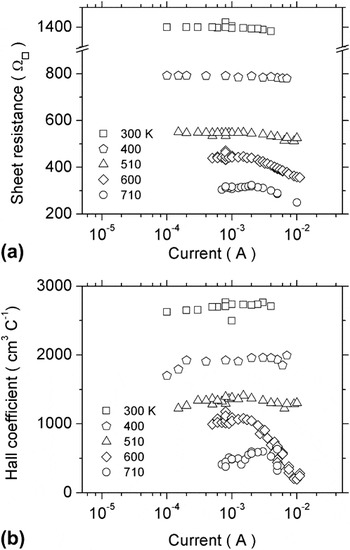
The results of sheet resistance and Hall measurements have to be independent of the intensity of the measurement current used.Reference Putley16 Therefore the following procedure for determining the appropriate measurement current for each Al-implanted sample has been applied. At a fixed temperature, sheet resistance and Hall coefficient have been measured for current values varying within a few decades. Typical results are presented in Figs. 1(a) and 1(b). These plots show that the plateau region, indicating an ohmic behavior, shrinks with increasing measurement temperature for both sheet resistance and Hall coefficient. The authors of this article have taken care to perform sheet resistance and Hall coefficient measurements by using a fixed current value within the range for which both sheet resistance and Hall coefficient resulted current independent at every temperature in the range of 140–720 K.
(a) Sheet resistance and (b) Hall coefficient versus current of measurement for different temperatures of measurement. The latter are given in the inset. Data are those of sample 4 × 1020 cm−3 Al+ implanted (triangles in Fig. 4).

Magnetic fields of 8000 and 10,000 Gauss have been used for Hall effect characterizations. As these are low intensity fields, the Hall scattering factor for holes rH can be different from 1. The temperature dependence of rH is also an issue, and different approaches to the analysis of Hall data can be found in the literature. An rH decreasing with increasing temperature T has been empirically obtained for epitaxial p-type 4H-SiC with Al dopant concentration in the range 1.8 × 10¹⁵ to 2 × 10¹⁸ /cm3.Reference Schmid, Krieger, Laube, Pensl, Wagner, Choyke, Matsunami and Pensl17 Such a trend is, however, opposite to the expected one in the frame of the relaxation-time approximation. Some authors have then used the experimental dependence of rH on temperature rH(T)Reference Schmid, Krieger, Laube, Pensl, Wagner, Choyke, Matsunami and Pensl17 to account for both Hall carrier and mobility data of Al-implanted 4H-SiC sample with Al concentrations in the range of 3.3 × 10¹⁸ to 1 × 10²¹ /cm3.Reference Pernot, Contreras and Camassel18 This range is, however, above the range for which the validity of rH(T) has been demonstrated.Reference Schmid, Krieger, Laube, Pensl, Wagner, Choyke, Matsunami and Pensl17 Other authors have used rH(T) = 1 for modeling the Hall carrier data, while using the rH(T) dependence obtained by the relaxation-time approximation for modeling the Hall mobility data of the same Al-implanted 4H-SiC samples with implanted Al concentrations in the range of 1.8 × 10¹⁸ to 5.5 × 10¹⁹ /cm3.Reference Koizumi, Suda and Kimoto19 In the following of this article, original experimental Hall carrier and mobility data using rH(T) = 1 will be shown. A qualitative analysis of these data, whose conclusions are independent of rH(T), will be presented. In addition, a preliminary simulation of a Hall carrier curve by the approach given in Ref. Reference Nath, Scaburri, Rao and Nipoti20 will be performed.
III. RESULTS
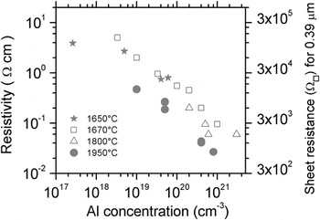
Open symbols in Fig. 2 show some of the previously published p-type resistivity values at room temperature (RT) of Al-implanted epitaxial 4H-SiC, illustrating the trend of increasing implanted Al concentration and increasing thermal annealing temperatures up to the maximum values of 4 × 10²¹ /cm3 and 1800 °C, respectively. In these cases the annealing time has been a few tens of minutes long. Circular filled symbols in Fig. 2 show the p-type resistivity data obtained in this study for similar implanted Al concentrations and thermal annealing at 1950 °C for 5 min. In spite of the shorter annealing time the data obtained in this study are a factor of 5, or more, lower than the previously published values. The filled stars symbols in Fig. 2 show unpublished results by the authors of this study obtained on Al-implanted epitaxial 4H-SiC that has been annealed in the same inductively heated furnace, but at a lower temperature (1650 °C) for 20 min.
Room temperature resistivity, and corresponding sheet resistance for a 0.39 μm thickness layer, of Al+ implanted 4H-SiC materials versus implanted Al concentration. Hollow symbols are published data on epitaxial 4H-SiC (squareReference Negoro, Kimoto, Matsunami, Schmid and Pensl7, triangleReference Sundaresan, Rao, Tian, Ridgway, Schreifels and Kopanski8). Circle filled symbols are the original data of this study, while star filled symbols are author?s unpublished results obtained for Al+ implanted epitaxial 4H-SiC material annealed by using the same inductively heated furnace but at a lower temperature. Annealing temperature is shown in the inset. Annealing time of stars, square and triangle are ≥ 20 min, that of circle is 5 min.

The resistivity scale on the left hand vertical axis of Fig. 2 has been converted into sheet resistance on the right hand vertical axis, taking into account the thickness of the box shaped implanted profile. A minimum sheet resistance of 890 Ω□ for a 0.39 μm p-type layer has been obtained in this study.
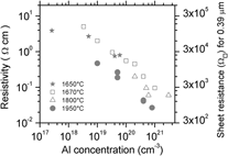
Resistivity and sheet resistance for a 0.39 μm thick Al+ implanted 4H-SiC layer with different Al concentrations are compared for the post implantation annealing of this study (CA open symbols) and that of ref. Reference Nipoti, Nath, Rao, Hallén, Carnera and Tian10 (MWA filled symbols) that was performed in a microwave heating system. Annealing temperatures and annealing times are given in the inset.

Figure 3 compares the resistivity and sheet resistance results obtained in this study and results obtained by microwave annealing (MWA) from Ref. Reference Nipoti, Nath, Rao, Hallén, Carnera and Tian10 for the same Al-implanted 4H-SiC material. MWA has been performed at a higher temperature but a shorter time. More precisely, 2000–2100 °C and 30 s compared to 1950 °C and 5 min using conventional thermal annealing. Figure 3 shows that the two different annealing processes have produced very similar electrical features in the Al-implanted 4H-SiC layers.
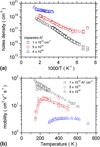
Figures 4(a) and 4(b) show the Hall carrier (a) and Hall mobility (b) data for three samples of this study: Al+ implanted with concentrations of 1 × 10¹⁹, 5 × 10¹⁹, and 4 × 10²⁰ /cm3. The first sample shows a monotonous decrease of the carrier density and a monotonous increase of carrier mobility for a decreasing measurement temperature in the range of 140–600 K. The second sample shows first a decrease, followed by a minimum and than an increase of carrier density, corresponding to an increase, a maximum and a decrease of carrier mobility with decreasing measurement temperature in the range of 140–500 K. The last sample shows almost constant carrier density and carrier mobility in the 300–720 K temperature range. The data of Figs. 3 and 4 correspond to a constant rH(T) equal to 1, but the qualitative trend seen in the figure will be the same also if the temperature dependence of rH(T)Reference Schmid, Krieger, Laube, Pensl, Wagner, Choyke, Matsunami and Pensl17, Reference Pernot, Contreras and Camassel18 is taken into account.
(a) Hall carriers and (b) Hall mobility for tree significant Al+ implanted 4H-SiC samples after 1950°C 5 min conventional thermal annealing. These samples have been implanted over an identical layer thickness of 0.39 μm with different Al concentrations that shown in the inset.

III. DISCUSSION
The comparison in Fig. 2 between the results of this study and the previously published values show that the p-type doping of Al-implanted 4H-SiC can be still further improved by maintaining the concept of increasing the Al-implanted concentration per unit volume and increasing the annealing temperature of a conventional postimplantation thermal treatment. In fact, in this study the increase of the annealing temperature from 1800 to 1950 °C has permitted a p-type implanted 4H-SiC material with a resistivity in the low 10−2 Ω cm range at RT. This is an excellent result and this p-type resistivity value is now only one decade higher than the lowest n-type resistivity at RT obtained for P-implanted 4H-SiC.Reference Nipoti, Nath, Qadri, Tian, Albonetti, Carnera and Rao4 Yet the absence of saturation for the resistivity data of the samples annealed at 1950 °C (see filled circle symbols in Fig. 2) allow us to hypothesize that a further improvement could be possible.
The first indication that it is indeed possible to overpass the previously published p-type resistivity values for Al-implanted 4H-SiC was recently shown for postimplantation MWA.Reference Nipoti, Nath, Rao, Hallén, Carnera and Tian10 A comparison between these MWA results and results obtained in this study is shown in Fig. 3 and makes evident that the two sets of data are very similar in spite of the higher temperature of MWA, i.e., 2000–2100 °C compared to 1950 °C for the conventional thermal annealing used in this study. This may be due to too short annealing time in the MWA study, i.e., 30 s and 5 min, respectively, but it could also be due to the fact that the limit of solid solubility of Al in 4H-SiCReference Linnarsson, Janson, Zimmermann, Svensson, Persson, Hultman, Wong-Leung, Karlsson, Schöner, Bleichner and Olsson12 has already been reached at 1950 °C. To discriminate between these two options, a dedicated study is necessary. Presently, conventional heating systems using inductive or resistive heating are most often used for postimplantation annealing of SiC. However, the increased versatility offered by MWA, i.e., faster and higher temperature cycles, opens up new possibilities for optimization of the annealing process for ion-implanted SiC.
The trends of Hall carrier and mobility data in Figs. 4(a) and 4(b) indicate that the carrier transport mechanism in the implanted 4H-SiC layers changes with increasing Al concentration. The monotonous trends of the Al-implanted sample with a concentration of 1 × 10¹⁹ /cm3 are typical for valence band extended state conduction. This is the only case for which the density of electrically activated acceptors, their ionization energy levels, as well as the compensation ratio of the activated dopant can be obtained by fitting the neutrality equation at different temperatures to experimental Hall carrier data. With respect to SiC with dopant concentration below 1015 /cm3, or not compensated, the effect of an elevated doping density and compensation results in a reduction of the dopant thermal activation energy.Reference Schöner, Nordel, Rottner, Helbig and Pensl21 By using the simulation approach given in Ref. Reference Nath, Scaburri, Rao and Nipoti20, a 73% electrical activation with 31% compensation and a single ionization energy level of 146 meV have been obtained for this 1 × 10¹⁹ /cm3 Al-implanted and 1950 °C/5 min annealed 4H-SiC sample. As expected, the obtained Al thermal ionization energy value is lower than in diluted 4H-SiC(Al) because of a higher dopant concentrationReference Koizumi, Suda and Kimoto19, Reference Choyke and Pensl22 and it is also lower than in almost uncompensated epitaxial 4H-SiC of similar acceptor concentrationReference Koizumi, Suda and Kimoto19 because of a higher compensation value.Reference Schöner, Nordel, Rottner, Helbig and Pensl21
In spite of the elevated degree of compensation, carrier density and mobility values of this 1 × 10¹⁹ /cm3 Al-implanted sample, as well as those of the sample implanted to the higher Al density of 5 × 10¹⁹ /cm3, are higher than corresponding values measured on epitaxial 4H-SiC material with lower Al acceptor concentration and lower compensation.Reference Koizumi, Suda and Kimoto19 This comparison indicates that a high activation and a large reduction of implantation-induced defects are reached. For the Al-implanted concentration of 5 × 10¹⁹ /cm3, a minimum in the Hall carrier curve at about 160 K is evident [Fig. 4(a)]. At high temperatures conduction due to an extended states transport can be undoubtedly hypothesized. But at low temperature the rising up of the carrier density after a minimum [Fig. 4(a)] and the drop of the mobility [Fig. 4(b)] may support the hypothesis of a mixed conduction with an another transport channel next to the extended states. In principle, such a low-temperature transport could be due to either a conduction through bulk impurity states or through localized states, both placed at the surface of the active layer or at its interface with the substrate. However, the origin of a surface/interface conductivity is expected to be mainly related to the formation of localized defects, and to be weakly dependent on the doping only through variations of the Fermi energy. This is not the same for the impurity band conduction, which is expected to increase with doping. Therefore, by increasing the doping, a surface/interface parallel channel should have generally a progressively smaller conductivity than the extended state one, with a shift of the minimum in carrier densities toward lower temperatures. On the contrary, in the case of impurity band conduction, an opposite shift toward higher temperature is expected, as effectively observed in Fig. 4(a), till to a nearly temperature-independent hole density curve at the semiconductor-to-metal transition for an high enough doping. For all that, the hypothesis of impurity band conduction more than that of a surface/interface conduction appears to explain the trend of the Hall data of the samples of this study. The formation of these intraband states are favored either by an increased amount of Al in substitutional positions or a considerable disorder in the 4H-SiC lattice, although the presence of disorder may be excluded because of the high values of the measured carrier mobility. As previously mentioned, we suspect that that the electrical activation of the implanted Al in 4H-SiC can increase further by increasing the Al-implanted dose. The 5 × 10¹⁹ /cm3 Al-implanted sample has a hole mobility maximum at about 230 K [Fig. 4(b)] that could correspond to a crossing point where the acoustic phonon scattering begins to dominate over ionized impurity scattering. Such behavior is also indicated by the mobility model published in Ref. Reference Pernot, Contreras and Camassel18. However, the steep decrease in mobility at temperatures lower than about 160 K is possibly linked to the onset of the impurity band conduction. At a still higher Al-implanted concentration 4 × 10²⁰ /cm3, the onset of an impurity band conduction seems to take place at a temperature as high as 350 K and the mobility is almost independent of the temperature.
IV. CONCLUSION
This study shows that the efficiency of p-type doping of 4H-SiC by Al ion implantation can be significantly improved by increasing the implanted Al concentration and, perhaps more importantly, by increasing the temperature of the conventional postimplantation annealing process to 1950 °C. In this study we have shown that it is possible to reach a p-type resistivity of Al-implanted 4H-SiC in the low 10−2 Ω cm region and a sheet resistance value of 890 Ω□ for a 0.39 μm thick 4H-SiC layer. These results are a factor of five better than what has been previously published and shows that p-type doping of 4H-SiC by Al ion implantation has further potential to improve the SiC device technology.
ACKNOWLEDGMENTS
Corresponding author warmly acknowledges the stimulating support of Prof. Mulpuri V. Rao for this study and Dr. Cristiano Albonetti for AFM measurements. The valuable collaboration with the staff of the clean rooms and of the electrical department of CNR-IMM of Bologna are acknowledged for sample processing and electronic instruments set-up, respectively. Mr. Salvatore Vantaggio is acknowledged for the efficient support during low temperature Hall effect characterizations.