INTRODUCTION
Novel high-precision radiotherapy (RT) techniques, including intensity-modulated radiation therapy and volumetric-modulated arc therapy, allow improved dose distribution within the target and spare a greater portion of normal tissue than conventional RT. These techniques involve accurate tumour volume delineation as well as verification of target localisation and monitoring of organ motion, also the tumour response assessment during treatment delivery. New state-of-art imaging modalities and their applications for radiation therapy are continuously being developed. Such systems are incorporated in radiation therapy treatment delivery and are known as image-guided radiotherapy (IGRT) systems. ExacTrac (BrainLAB AG, Feldkirchen, Germany) is one among IGRT tools that is used for patient setup and pre-treatment geometrical verification of the patient.
ExacTrac is a major tool for quickly positioning and acquiring images for IGRT of the patient in a busy department.Reference Jin, Yin, Tenn, Medin and Solberg 1 , Reference Soete, Verellen and Michielsen 2 It is based on two-dimensional (2D) oblique images and infrared (IR) markers. The patients are monitored with the help of IR markers during the treatment time. For certain treatments viz frameless stereotaxy, ExacTrac provides a quick way of positioning the patient on treatment couch at the isocentre of linear accelerator. ExacTrac comprises of a floor-imbedded X-ray unit with ceiling mounted imaging panels for obtaining X-ray images and also an IR camera, mounted from ceiling to detect the motion of IR markers placed on the patient’s body.Reference Wagner, Meeks and Bova 3 , Reference Wang, Solberg, Medin and Boone 4 For the efficient utilisation of the ExacTrac device, its calibration is of utmost importance. If the isocentre is not localised for daily ExacTrac calibration then there may be chances of errors in patient setup. In addition, the errors can propagate through the positioning of ExacTrac, IR and X-ray calibration tools, image matching software limitations and estimation of shift made by software. Altogether, these uncertainties comprise of the errors that cannot be corrected because these are due to the fact that system behaves in this manner.
Assessment of these inherent errors, calculating systematic and random errors separately due to system limitations have not been studied by any research group to date. As these inaccuracies are viewed as trivial, however, they can still be assessed and used for the departmental quality control programme to monitor the equipment performance. Any unexpected change in the behaviour of the software for image matching can be fixed using this newly developed quality control protocol. Accurate patient positioning can also be ensured by such a stringent quality assurance (QA) programme for the in-room imaging system.
MATERIALS AND METHODS
Anthropomorphic pelvic phantom
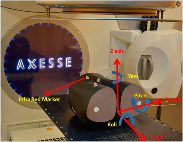
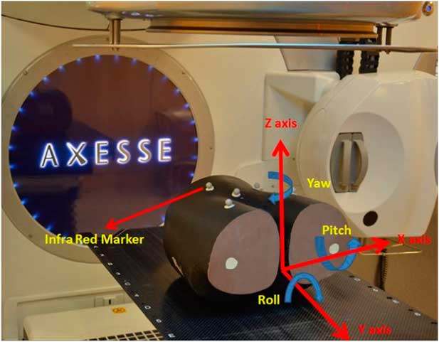
An anthropomorphic Brainlab pelvic phantom (BrainLAB AG), made-up of tissue equivalent material was used for the study; the bony landmarks inside the phantom provided adequate contrast for image matching between soft tissue and bone. The phantom was also used on 6D couch HexaPOD (BrainLAB AG), that is subjected to a daily QA programme (Figure 1). This phantom was preferred for this study because of its shape, replicating human anatomy and availability in the department.
Anthropomorphic pelvic phantom placed on six-dimensional HexaPod table top with translational and rotational shifts.
Oblique radiographic pair
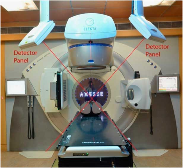
An oblique pair of radiographs was used for image acquisition by ExacTrac. This system has many combinations of X-ray energies for acquiring images of different parts of the patient’s anatomy; depending on site, thickness and presence of bony structures as bony structures require a higher X-ray energy to penetrate and to form better image contrast. For the production of X-rays, two X-ray generators, imbedded in the floor such that one is on the right and other on the left side of the patient plane with two fixed flat panel detectors mounted in the ceiling of the room were used (Figure 2). There were two possible ways of matching of these images, one manual and another automatic registration with the reference computed tomography (CT) images.
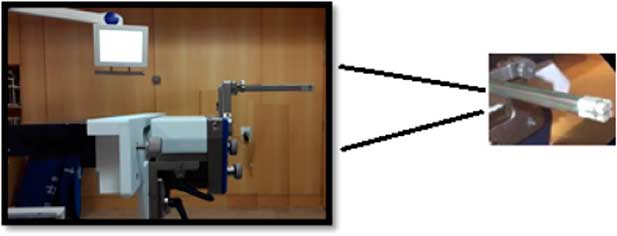
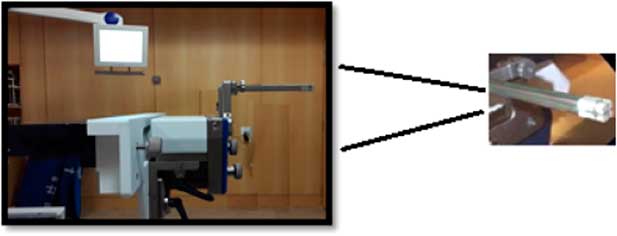
Winston Lutz test setup for ExacTrac and linac radiation isocentre verification.
Winston Lutz (WL) test for ExacTrac and linac isocentre
WL test was done to check the coincidence of radiological isocentre of ExacTrac with an Elekta Axesse linac (Elekta Oncology System, Stockholm, Sweden) isocentre before starting the inherent translational and rotational shifts determination process. This test consisted of a hidden steel target (2-mm diameter) that was embedded in 5 cm cube of tissue equivalent material and rigidly attached to the linac couch. For the test, The WL pointer was positioned using the lasers defining the isocentre and then imaged using oblique radiographs taken using the ExacTrac. In this study, it was found that the isocentre of the ExacTrac and that of the linac lies within a 1-mm diameter. The experimental setup conditions for the WL test are shown in Figure 3. The test was performed on first day before starting the study so that any undesirable shifts between the isocentre of linac and isocentre of ExacTrac system will be nullified, and subsequently not affect the result of our study.
The Axesse image-guided system showing oblique configuration of X-ray imaging devices.

METHODS
The study was performed with an Elekta Axesse linear accelerator (Elekta Oncology System) and ExacTrac imaging system. For the generation of reference dataset, pelvic body phantom was scanned with 1·5 mm slice thickness as for our institutional protocol for stereotactic body radiation therapy patients on a 16-slice PET Philips CT scanner, which was available in our department (Light Speed; Philips Medical Systems, Amsterdam, the Netherland) and digital imaging and communications in medicine images after CT scan were imported in MONACO Sim (V5.00.02; CMS Elekta, Sunnyval, CA, USA) contouring workstation for body contouring and target localisation. Reference CT images were imported into the ExacTrac system as ExacTrac required a full reference dataset to create a reference digitally reconstructed radiograph (DRR) to match with acquired 2D image dataset.
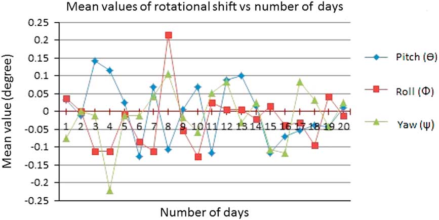
The ExacTrac stereoscopic imaging system is also equipped with an IR camera which can track the position of IR markers, and in this case attached to the surface of the phantom. The system is capable of calculating the translational and rotational shifts in six dimensions—that is, three translational motions (x, y, z) and three rotational motions (θ, Ф, ψ), rotational shifts were known as pitch, roll and yaw, respectively, where pitch was rotation along x axis, roll was rotation along y axis and yaw was rotation about z axis (Figure 1). To assess the reproducibility in the calculation of shifts by ExacTrac system, the isocentre of the phantom using IR markers, was placed near the isocentre (within 2-mm diameter) of linac and images were taken 20 times a day for 20 conjugative days for reproducibility of results to mirror a typical treatment sequence. For a given day, the shifts determined for the first imaging instance was kept as a reference and for remaining 19 imaging instances, the differences in shifts from the first reference readings were computed. The mean value of translational and rotational shifts for 19 imaging instances was calculated in both directions. The method was repeated for 19 consecutive days. On the basis of the mean translational and rotational directions, the mean and standard deviations of the deviations were calculated for each day and systematic and random errors were calculated based on these standard shifts. Only translational shift were considered for the margins calculation using Van Herk formula because rotational shifts cannot be directly used in margin calculation formula. The Van Herk formula consist two parts, one for systematic and other for random errorsReference Van Herk 5 :
 $${\rm Margin}{\equals}\left( {(2.5{\times}{\rm SD}\,(\Sigma )){\plus}(0.7{\times}{\rm RMS}\,(\sigma ))} \right),$$
where SD (Σ) is standard deviation of the mean for 20 days readings and RMS (σ) is the root mean square of the standard deviation of these mean readings.
Results
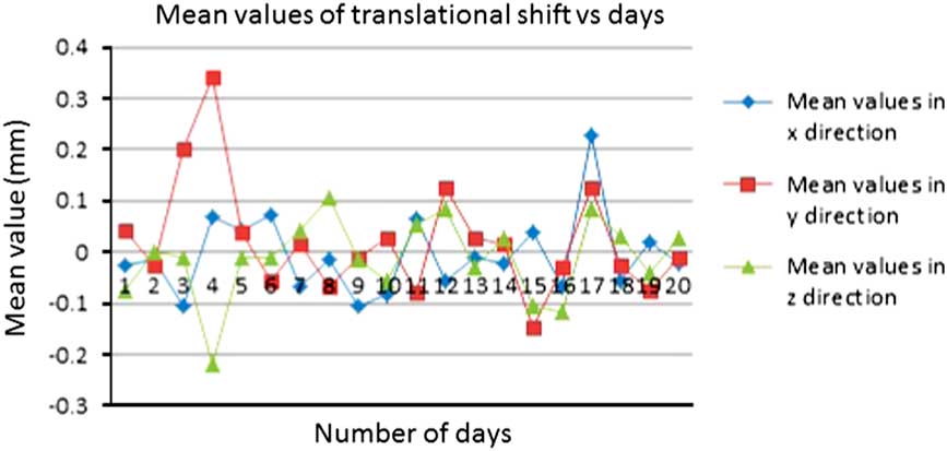
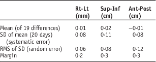
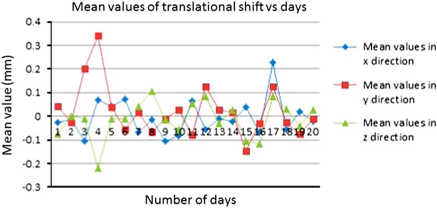
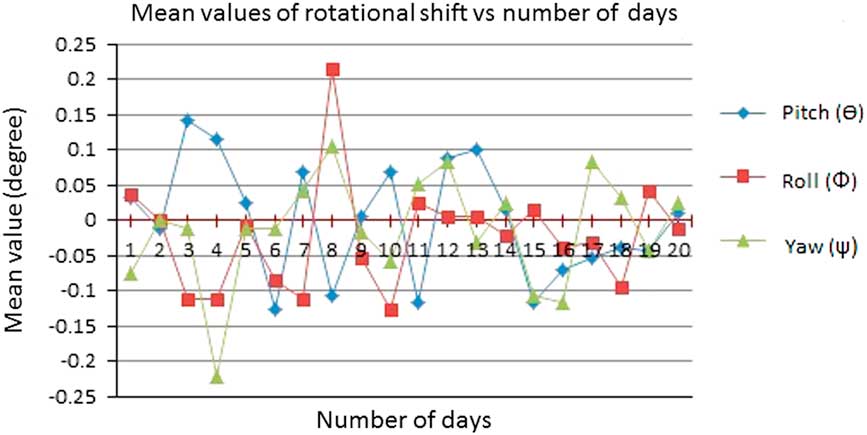
Translational and rotational shifts in 6D for each day were calculated, considering the first reading of the day as a reference one, so that the errors in the shifts due to different days phantom positioning on the cough was nullified (Figures 4 and 5). Mean values of 19 days readings were calculated and found as 0·001±0·008 cm in right-left (Rt-Lt) direction, 0·002±0·01 cm in superior-inferior (Sup-Inf) direction and −0·001±cm in anterior-posterior (Ant-Post) direction. Standard deviations of these 20 days mean reading (systematic errors) were also calculated and found as 0·008 cm in Rt-Lt direction, 0·011 cm in Sup-Inf direction and 0·008 cm in Ant-Post direction. Root mean square of the standard deviation was calculated (random errors), found as 0·006 cm in Rt-Lt direction, 0·008 cm in Sup-Inf direction and 0·012 cm in Ant-Post direction. On this basic, margins were calculated using van Herk formula because this formula was used clinically in our institute for margins calculation from clinical tumour volume to planning target volume (PTV). There was a 0·02 cm inherent shift in Rt-Lt direction, 0·03 cm in Sup-Inf direction and 0·03 cm in Ant-Post direction.
Translational shifts versus number of days.
Rotational shifts versus number of days.
Discussion
ExacTrac is one of an apt imaging system for patient positioning and image verification for stereotactic radiosurgery (SRS) and stereotactic radiotherapy (SRT) patient treatment.Reference Takakura, Mizowaki and Nakata 6 – Reference Ryu, Fang Yin and Rock 9 There is some associated uncertainty with the imaging system which is incorporated in clinical target volume to PTV margin. Ideally the ExacTrac system should show same translational and rotational shifts to achieve accurate patient positioning for every fraction if procedure would be repeated multiple time. In several studies, an attempt had been made to calculate spatial and setup uncertainty analysis in the ExacTrac systemReference Shi, Tazi, Fang and Iannuzzi 10 – Reference Hayashi, Obata, Uchiyama, Mori, Hashizume and Kobayashi 12 but none of these publications had estimated inherent uncertainty associated with the system due to the software and image registration.
2D localisation images are obtained by kV X-ray of ExacTrac with high spatial resolution and these images are matched with 3D CT-simulation images using 6D fusion algorithm. Position of kV X-ray source and panel are fixed and coincide with linac isocentre defined by the room laser, which make it a suitable IGRT system especially for rigid bony structures, such as spinal and cranial lesions. Its operation is simple, fast and deliver comparatively lower imaging dose than 2D MV portal and cone beam computed tomography (CBCT) imaging.
Although, ExacTrac is very fast and images can be taken within a fraction of a second, there is still a chance that the ExacTrac isocentre can move from the isocentre of linear accelerator after a period of time which emphasises the importance of periodic QA. The uncertainty in image matching also depends upon the stability of the localising object, quality of 2D radiographs and the reference DRR images. The shifts obtained were 6D although the imaging system was 2D. In the context of a multimodality treatment programme, image guidance through ExacTrac appears to be of utmost importance and depicts that uncertainty in SRS is more than SRT, using ExacTrac imaging modality.Reference Ackerly, Lancaster, Geso and Roxby 13 CBCT performance against ExacTrac was also evaluated and shows a general agreement between both imaging modalities,Reference Ma, Chang, Wang, Wu, Kirkpatrick and Yin 14 although image acquisition time and irradiated volume were more in CBCT. The ExacTrac automatic fusion algorithm was accurate and quick and has automated correction fusion without doing manual fusion.Reference Jin, Ryu and Faber 15
Table 1 gives the mean value of the means of each day’s translational shifts, after considering first reading of the day as a reference one and subtracting from remaining 19 readings of the same day, its standard deviation (systematic error) and root mean square of the standard deviation (random error). The table also shows the estimated margins to account for the uncertainty in shifts determination by the software. Reproducibility in determination of shifts was established for ExacTrac system. Differences observed can be attributed to the random nature in photon interactions with matter and its subsequent influence on the image quality produced by the uncertainties involved with the software. Ideally, the ExacTrac system should function without giving any shifts if a static phantom will be imaged again and again but due to the limitations like statistical nature of interaction of radiation with the phantom and uncertainty in the algorithm used for radiograph formations and matching it with reference radiograph, the shifts were observed.
Mean, SD, systematic and random errors and margins for uncertainty in ExacTrac imaging system

Abbreviation: RMS, root mean square; Rt-Lt, right-left; Sup-Inf, superior-inferior; Ant-Post, anterior-posterior.
Conclusions
This study demonstrates that there were inherent uncertainties in the ExacTrac imaging system due to the software and automatic image registration. These systematic and random errors were calculated and used for a baseline value to use for the future quality programme for ExacTrac system. Image-guided treatment delivery systems should be tested for all influencing factors before its clinical use. The ‘margins’ required to account for the uncertainties in shifts determination are found to be <0·3 mm in all directions. Currently there are no guidelines or recommendations for this parameter. However, a figure of <0·3 mm seems acceptable and in any case should not cause any undue concerns regarding the reliability of the ExacTrac system for clinical use.
Acknowledgement
Special thanks to Dr Anusheel Munshi, Dr Kanan Jassal, Dr B.R.K. Gupta, Dr T. Ganesh and Fortis Memorial Research Institute hospital for their support and help during preparation of the study.