I. INTRODUCTION
Direct deposition using a focused ion beam (FIB) is a prospective method for nanoscopic fabrication.Reference Koops, Kretz, Rudolph, Weber, Dahm and Lee1–Reference DeMarco and Melngailis3 In particular, FIB-induced chemical vapor deposition (FIB-CVD) has distinct advantages in creating complicated structures.Reference Matsui, Kaito, Fujita, Komura, Kanda and Haruyama4 Such microstructures are composed of deposited beam members made from amorphous carbon (a-C). Therefore, the overall structural characteristics are, in principle, determined by the mechanical behavior of the member itself. Recently, it was found that nanopillars (hereafter referred to as pillars) made by the above-mentioned technique have a large rubber-like nonlinear deformability before fracture.Reference Shibutani and Yoshioka5 Their curious mechanical and structural properties promote a coherent understanding of a-C pillars as deformable bodies with size-dependent properties, unlike bulky a-Cs [such as diamond-like carbon (DLC)] which are typically brittle materials that fracture with little elongation.
We recently developed a unique materials testing procedure, capable of measuring both infinitesimal deformation and large deflection of pillars with high accuracy. To avoid unfavorable nanoscale effects at the loading point due to sticking forces such as Coulomb interactions and meniscus forces, we proposed an original double-cantilever test based on the rigid connection of two pillars using a focused electron beam (EB) deposition technique in a scanning electron microscope (SEM).Reference Tanaka, Shinkai, Shibutani and Kogo6 This original approach enables highly accurate measurement of large deflections by controlling the applied displacement with a commercial cantilever normally used in an atomic force microscope (AFM). In the present report, the effect of size on the large nonlinear deformability of pillars is discussed on the basis of several samples with different diameters and diameter-to-length ratios. In addition, nanocoils (called coils hereafter) with several spring geometries were axially elongated to obtain their torsional rigidities as well as the flexural rigidities of pillars using the above-mentioned cantilever testing because the linear elastic properties are sensitive to internal structure changes.
II. BENDING AND TORSION TESTS
Pillars were grown using a commercial FIB system (SMI9200, SII NanoTechnology Inc., Chiba, Japan) with a Ga+ ion beam in the supplied phenanthrene vapor (C14H10) precursor gas. The settings for the FIB fabrication of pillars were an accelerating voltage of 30 keV and a beam diameter of about 7 nm at a probe current of 1 pA. The pillar diameter was determined by the depth of ion penetration, electron dispersion, and ion beam diameter.Reference Fujita, Ishida, Ichihashi, Ochiai, Kaito and Matsui7
A. Bending tests using DC specimens
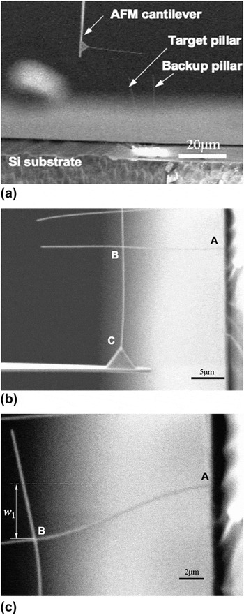
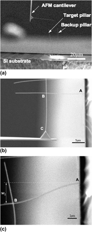
For bending tests intended to determine the size effect of deformability, a double-cantilever specimen (abbreviated hereafter as a DC specimen) was assembled by connecting two pillars with almost equal diameters and equal longitudinal lengths.Reference Tanaka, Shinkai, Shibutani and Kogo6 The two pillars were deposited on separate basal plates, one of which was on the tip of a commercially available AFM cantilever used to enforce the prescribed displacement to DC specimen [Fig. 1(a)]. The pillars were then joined at their intersection point B in Fig. 1(b) using a focused EB in a SEM (JSM5310, JEOL Ltd., Tokyo, Japan, background pressure: ∼10−4 Pa). The EB exposure decomposed the pump oil in a SEM, resulting in the deposition of residual hydrocarbons at the pillar intersection.Reference Koops, Kretz, Rudolph, Weber, Dahm and Lee1, Reference Nishio, Sawaya, Akita and Nakayama8 The joint stiffness was therefore explicitly dependent on the EB exposure time. A longer exposure produced a higher rotational rigidity of the joint, and the present work adopted an exposure time of 120 s to maintain a right angle at the intersection, even under bending [Figs. 1(b) and 1(c)]. After the above preparation, large deflection tests were performed by applying a load to the DC specimen, which encompassed the AFM cantilever for measurement of the applied lateral force. The displacement w 1 of the horizontal pillar [Fig. 1(c)] and the displacement w 2 of the AFM cantilever were measured in situ by SEM.
Scanning electron microscope (SEM) images showing a sequence of bending tests using a double-cantilever (DC) specimen. (a) Setting up two pillars. (b) Joining the two pillars by electron beam at point B. (c) Bending a DC specimen.

B. Torsion tests using nanocoils
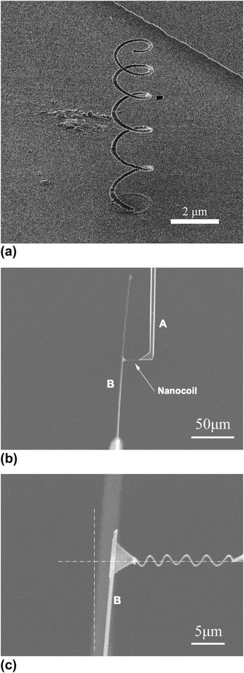
Generally, the present pillar intrinsically possesses a large nonlinear deformability under bending, which has already been reported in Ref. Reference Shibutani and Yoshioka5. Meanwhile, the pillar has less elongation against tensile loading and, in consequence, exhibits very brittle fracture immediately after an infinitesimal linear deformation. These observations imply three fundamentally different molecular-level deformation mechanisms: stretching of a single a-C covalent bond, bending by a change in the angle between two bonds, and torsion by dihedral angle rotation, all of which could strongly affect the global deformation.Reference Shibutani and Yoshioka5 The tensile testing of nanocoils fabricated by the abovementioned process was performed because much less torsional resistance among the three fundamental deformation mechanisms is, in a major way, contributed to the global tensile deformation of coil, especially in the case of the close-coiled helical spring (its coil diameter is large in comparison with its pitch). One such coil, grown on a Si substrate, is shown in Fig. 2(a) as a typical example. This coil had a coil diameter of 1,500 nm and a pillar diameter of 170 nm. After bringing an AFM cantilever [denoted as A in Fig. 2(b)] to the free end of that coil, the contact point between the coil and the tip of cantilever A was joined by an EB technique in a SEM. Lifting the cantilever A detached the coil from the Si substrate, and the other AFM cantilever [denoted B in Fig. 2(b)], which had a spring constant much lower than that of A, was joined to the free end of the coil. The nominal spring constants of these cantilevers were 42 N/m for A and 0.08 N/m for B. After these manipulations, cantilever B was slowly translated along the axial direction of the coil to adjust any axial misalignment by hand [Fig. 2(c)].
Tensile test of nanocoil using two atomic force microscope cantilevers. (a) Nanocoil with coil diameter of 1,500 nm. (b) Set-up for tensile loading. (c) Applied axial loading.

III. EXPERIMENTAL RESULTS
A. Linear elastic properties
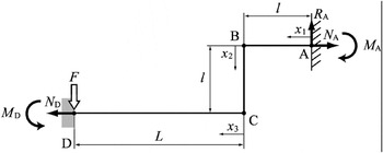
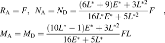
When a DC bending test specimen deforms infinitesimally, the analytical solution derived from elementary beam theory can afford two flexural rigidities: E 1I 1 and E 2I 2. E 1 is Young’s modulus for the pillar and E 2 is that for the cantilever. I 1 and I 2 are the geometric moments of inertia for the pillar and cantilever, respectively. Figure 3 shows the initial configuration and boundary conditions of the DC specimen. Because the system in Fig. 3 is indeterminate in structural mechanics, the unknown reaction forces R A, N A, and M A can be derived from the equilibrium of forces and moments, and from the compatibility condition on deformation, as follows:
Initial configuration and boundary conditions of a DC specimen in the linear elastic region.

where dimensionless parameters are defined as E* = E 1I 1/(E 2I 2) and L* = l/L. Hence, the following deflections w 1 and w 2 are determined from Eq. (1).

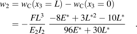
Moreover, E* can be defined, by eliminating the force F of Eqs. (2) and (3), as follows:
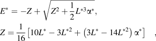
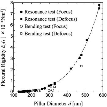
where α* is equal to w 2l/(w 1L) = (w 2/L)/(w 1/l), which represents the slope in an infinitesimal linear region of the curve. The flexural rigidity E 2I 2 of the commercial cantilever used in the DC specimen is known. Therefore, the flexural rigidities E 1I 1 of the pillars can be obtained from Eq. (4). Figure 4 compares the obtained flexural rigidities from the present bending tests with those from resonance vibration testing (see Ref. Reference Shibutani and Yoshioka5 for the experimental procedure). These flexural rigidities of samples with diameters around 160 to 600 nm agree well with the values from resonance vibration tests, and it can be understood that E 1I 1 is proportional to the fourth power of the diameter, i.e., the geometric moment of inertia (I = πd 4 / 64 ∝ d 4 where d is the pillar diameter). The dashed curve fitting to experimental data is E 1I 1 = 6.68 × 10⁹d 4 [Nm2] [where unit of d is (m)], thus Young modulus of pillar E 1 can be estimated as 136 GPa. Therefore, the proposed DC specimen could have high accuracy even for nanoscaled materials. In Fig. 4, there are two kinds of data different from the beam focusing methods. Although the precise amorphous internal structure of a-C might change according to the focusing method, all of the data fell remarkably close to the dashed prediction line based on the fourth power of the diameter. As a natural consequence of this, no specific size effect of pillar was observed within the linear elastic deformation region that resulted from reversible molecular movement.
Comparison of flexural rigidity by bending test (open symbols) with that by resonance vibration test (solid symbols). A dashed line is fitted to the experimental data as the function of fourth power of diameter; E 1I 1 = 6.68 × 10⁹d 4 [Nm2] [where unit of d is (m)].

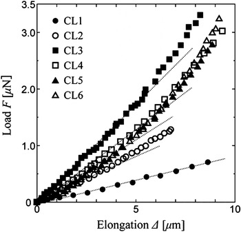
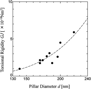
Tensile tests of 10 coils provided highly linear responses in the relatively smaller deformation region, as shown in Fig. 5. Six of these coils were denoted CL1 to CL6 and ranged in coil diameter from 1,440 to 1,620 nm and in pillar diameter from 140 to 200 nm. Using only the slope of linear region, the torsional rigidity of the coil GJ, where G is the shear modulus and J is the polar inertia of moment, can be obtained by spring mechanics.Reference Chen, Zhang, Dikin, Ding, Ruoff, Pan and Nakayama9 Preliminary studies using the above coil geometries conclude that the contributions of spring constant components from tension and shear force are less than 1%, and thus those from only bending and torsion were considered. Substituting the measured slopes in Fig. 5 and the approximated function on E 1I 1 of pillar in Fig. 4 into the relation of spring constant in Ref. Reference Chen, Zhang, Dikin, Ding, Ruoff, Pan and Nakayama9, GJs are calculated according to pillar diameter, as shown in Fig. 6. You can see that the torsional rigidities are roughly proportional to the fourth power of the diameter, as was the flexural rigidity E 1I 1 (because J = πd 4 / 32 ∝ d 4). The fitted dashed curve is GJ = 2.34 × 10⁹d 4 [Nm2] [where unit of d is (m)], thus shear modulus of pillar G can be estimated as 23.8 GPa. The isotropic condition for a continuous body of G = E 1/{2(1+ν)} does not hold under assumption of ν = 0.3. These two linear responses lead to two important conclusions: any outstanding size effect on pillar is not observed from the linear elastic properties because the prediction from elementary beam theory consistently holds under constant E or G. Furthermore, the torsional rigidity on the order of 10−18 was much weaker than the flexural rigidity on the order of 10−16. The latter suggests that among the three types of molecular-level deformation mechanisms mentioned above, torsion by molecular rotation is the primary mechanism of the initial global deformation.
Relationships between tensile load and elongation of several nanocoils in the linear elastic region.

Change in torsional rigidity according to pillar diameter of the coil. A dashed line is fitted to the experimental data as the function of fourth power of diameter; GJ = 2.34 × 10⁹d 4 [Nm2] [where unit of d is (m)].

B. Large deflections
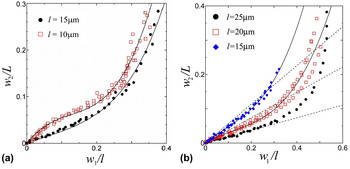
Figures 7(a) and 7(b) show large deflection curves for pillars of two different diameters (d = 160 and 220 nm) with changing pillar length l from 10 to 25 μm. The normalized deflection w 1/l of the pillar and the normalized deflection w 2/L of the cantilever are shown. The latter is mechanically equivalent to the lateral force applied to the pillar via the spring constant of the used AFM cantilever. Remember that the upper pillar was under a lateral force and bending moment at the joint where w 1 was measured. In these experiments, the linear and large (except ultimate) deflection behaviors of the pillars conformed well to the fitted curves of third-order polynomials (solid lines in Fig. 7). The dashed lines in Fig. 7(b) indicate the linear response fitted to the initial slopes. The large deflection curves in Fig. 7(a) indicate a slight decrease in deformation resistance (softening) after the initial linear response, which is especially remarkable for a diameter of 160 nm and a length of 10 μm. Increasing the length to 15 μm while maintaining a diameter of 160 nm almost eliminates this softening effect. At a finite deflection w 1, all pillars become hardened due to the geometrical nonlinearity because large deflection beam theory suggests that the axial rigidity of the beam is more significant than under an infinitesimal deflection.Reference Gere and Timoshenko10 The w 1–w 2 plots of pillars with the same diameter of 220 nm in Fig. 7(b) clarify that the softening was observed for lengths of 15 and 20 μm, but at 25 μm the beams had a nearly linear response before hardening. Consequently, there might exist some hidden geometric boundaries between these characteristic deformation behaviors.
Deflection curves for (a) d = 160 nm and (b) d = 220 nm, with changing pillar length. (a) d = 160 nm and (b) d = 220 nm.

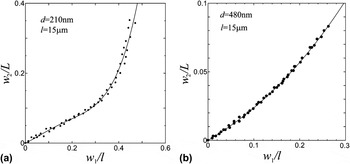
Maintaining a length of 15 μm while increasing the diameter to 480 nm, a gentler hardening region follows the nearly linear response up to half of the entire deformation, as shown in Fig. 8(b). Since macroscopic a-C materials such as DLC have been accepted as typical brittle materials with little elongation, these results suggest the possibility of a transition state from the molecular-based flexural behavior to the bulk-based brittle behavior. Note that the order of deflection w 2/L on the vertical axis of Fig. 8, for example, was determined by the spring constant of the AFM cantilever used in each experiment.
Deflection curves for (a) d = 210 nm and (b) d = 480 nm with a fixed length of l = 15 μm. (a) d = 210 nm and (b) d = 480 nm.

IV. DISCUSSION OF SIZE EFFECT
As mentioned in the previous section, the large deflection behavior of a typical pillar can be categorized into three regions: a decrease in the slope of the defection curve just after the linear elastic region, which is called softening region, and the final extremely hardening region. Some samples exhibited as the continuum body without any softening, while others had a nearly linear response over the entire deformation. These results can be summarized using two geometric parameters: the pillar diameter d (which determines the pillar volume) and the diameter-to-length ratio d/l. Bending tests were performed using more samples than are shown in Figs. 7 and 8, and all of the results are plotted in Fig. 9, which shows the d–d/l relationship. Recall that different AFM cantilevers were used for different samples, with spring constants of k = 0.39 N/m for d = 480 nm, k = 0.03 N/m for d = 310 nm, and k = 0.006 N/m for the others. Consequently, the quantities on the vertical axis of each deflection curve have been modified to unify the basis. If the sample had a diameter of less than 300 nm and a d/l ratio above 10−2, softening was always observed (open circles in Fig. 9). For other size regions, no decrease in the slope of the deflection curve was observed, and the samples behaved as continuous beam members (solid squares in Fig. 9). As mentioned in Fig. 8(b), the most upper-right point, with a diameter of 480 nm, had a nearly linear response. In the lower left region, where the pillar length l was much larger than the diameter d, the axial deformation could be so coupled to the bending that the deformation resistance became higher and higher, which has been certified by nonlinear deflection beam theory.
Deformation map showing the pillar size effect characterized as softening for diameters of less than 300 nm and diameter-to-length ratios above 10−2. All such pillars showed softening (open circles), which was not observed otherwise (solid square).

In light of the previous discussion of the infinitesimal linear elastic region with no size effect, the above-mentioned size effect likely originates from the nonlinear deformation accompanying molecular-level irreversible motion. The results imply that a pillar diameter of 250 to 300 nm may be the turning point and that this size regime can be thought of as a deformation embryo, which provides molecular-level deformability to the global deformation. Thus, this regime may be named the “a-C deformation cluster,” as was similarly discussed in Ref. Reference Kometani, Yusa, Warisawa and Ishihara11. At larger diameters, these molecular-level properties decay exponentially, and the macroscopic brittle property arises instead, due to the greatly disrupted mobility of the deformation cluster.
V. CONCLUSIONS
We investigated the size effects observed in nanopillars fabricated by FIB-CVD using a novel bending test based on DC specimens to precisely measure the large deflection of a-C pillars as well as their infinitesimal deflection. This testing afforded high accuracy, even for infinitesimal deformation, because it avoided unfavorable nanoscale effects at the loading point due to sticking forces. The results obtained from the bending tests indicated that the large deflection behavior of the pillar could be categorized into three regions: decrease of the slope in defection curve just after the linear elastic region, which is called softening region, and the final extremely hardening region. Softening was observed for all samples with diameters of less than 300 nm and diameter-to-length ratios above 10−2. The other samples deformed with a predictable continuum-like deflection behavior. Comparing the flexural and torsional rigidities in the infinitesimal linear elastic region, there were two important points to note: First, any outstanding size effect on the pillar is not observed from the linear elastic properties. Second, the torsional rigidity on the order of 10−18 was much lower than the flexural rigidity on the order of 10−16. This indicates that initially, of the three possible molecular-level deformation mechanisms, torsion by molecular rotation is predominantly responsible for the global deformation.
ACKNOWLEDGMENTS
The author (YS) deeply acknowledges the support from the Center for Atomic and Molecular Technologies of Osaka University, and the coauthor (YK) acknowledges the support from the Polyscale Technology Research Center of Tokyo University of Science.