I. INTRODUCTION
Congested microwave band and remarkable properties of terahertz radiations has invited attention of many researchers towards terahertz band. Recent advances in wireless communication, security and imaging instruments at terahertz range have drawn attention toward development of wideband, circular polarized (CP) and compact antennas that can be easily integrated with other active devices [Reference Siegel1–Reference Fernandes and Fernandes5]. Quasi optic approach of mounting these antennas at back of substrate lens has grown rapidly in last few years because of advantages of high directivity, compatibility with IC technique and suppressing of substrate mode losses at such high frequency. Therefore performance analysis of planar antennas with lens is of great importance [Reference Rutledge and Muha6–Reference Pasqualini and Maci9]. Most of the previously reported work has been focused on basic properties of linearly polarized slot antenna as feed on silicon or quartz substrate lens but such narrow band structures have different resonant behavior at such high frequency [Reference Otero and Eleftrieriades10–Reference Filipovic12]. On the other hand broadband antennas such as log spiral and log periodic are quite bulky and their large size is major hurdle for their applications in focal plane arrays (FPA). Since edge elements suffer from internal loss thus such large dimensions resulted into less number of elements at back side of lens. Whereas densely packed system is basic requirement for high resolution and better imaging property. Therefore broadband and compact antennas will be very attractive for use over wide frequency band with single device and occupying less space resulting in densely packed arrays [Reference Semnov13]. Whereas high directivity and CP are required features for wireless communications at this less congested part of frequency band [Reference Wu, Eleftheriades and Emilie14, Reference Migliaccio15]. All such applications demand designing and characterization of novel CP and wideband dipole antennas to overcome size limitations.
In this paper more attention has been focused for novel design of CP dipole antennas with substrate lens and full wave analysis has been carried out to study radiation characteristics as well as CP property of antennas with lens. Off axis depolarization effect is also studied carefully to conclude helpful guidelines for adjacent elements spacing and number of elements of CP antennas at back of substrate lens in array format. Two novel and CP half wave dipole antennas, cross bow tie (CBT) and clover leaf (CL) antennas, are designed for present work. In Section I we will briefly describe the geometries of feeds and lens designed by finite element method (FEM)-based high frequency structure simulator (HFSS). Section II will deal with array behavior of both designs mounted on lens for FPA. A criterion is set for adjacent elements spacing. Some modifications in antenna design are also suggested to improve uniformity of radiation patterns of edge elements of lens arrays. In Section III comparative analysis of radiation characteristics of each dipole antenna is carried out in terms of directivity variations for different lens dimensions and materials. Section IV deals CP property of antenna on lens. Off axis depolarization effect of lens on CP antenna is studied to determine the array size with better CP behavior.
II. SECTION I
A) Antenna geometries
Geometries of two novel dipole antennas CBT and CL antenna are shown in Figs 1(a) and 1(b). Proposed CBT consists of two dipole arms of unequal length with rounded corners. CBT antenna is positioned at center of quartz substrate of relative permittivity 2.94 and thickness 0.1 mm. Design parameters of CBT are L1 (length of large arm), L2 (length of small arm), Rc1(radius of larger rounded arm), Rc2 (radius of smaller arm). Bow angles are set to be 60° chosen by optimization [Reference Mir and Yu16]. Lengths of each dipole are chosen by numerous simulation to obtain CP by following the proposal given in [Reference Bolster17] for crossed dipoles. Geometry and parameter of CL antenna is defined in Fig. 1(b). It is composed of CL shaped 2 Patel shaped arms. Designing parameters of CL are L (length of both arm), W (width of arm), w (thickness of arm), Gx = Gy (gaps). Some geometrical modification has been done in conventional four leaf clover antenna reported in [Reference Nguyen18, Reference Woo19]. Two arms of clover antenna have been proposed in this work to get constant and lower impedance. CL antenna is placed at center of quartz substrate of relative permittivity 2.94 and thickness 0.4 mm. Dimensions of both dipole antennas are so chosen that total length of antennas corresponds to half wavelength. Similarity of both antenna‘s dimensions allows us to make a comparative analysis of radiation characteristics of these antennas pursuant to applications. The lens chosen for this purpose is made up of quartz (ε r = 2.94) to overcome substrate mode loss at lens surface. Extended hemispherical shape of lens is selected for presented work as outcome of this shape is remarkable alteration in field distribution inside lens. Radius and extension length of lens are labeled as R and L. Length of extended portion is normally chosen to be R/n where n is reflection coefficient. A proper choice of extension length results into considerable enhancement in lens ability to produce field spots of increased intensity which results into good receiving sensitivity [Reference Filipovic, Gearhart and Rebeiz11, Reference Nguyen20]. Both antennas are excited by GaAs Schottkey diode. For numeric study diode is replaced by a lumped port. Lumped port is selected for this work to provide good approximation for source specifically when calculating far field and it is appropriate excitation for antenna with required impedance to calculate S parameters and impedance matching to diode which is found to be 100 Ω at center frequency with very small variation at other frequencies after optimization of diode's parameters. Moreover both proposed antennas possess constant impedance of 100 Ω from 200 to 600 GHz. Therefore port impedance is set to be 100 Ω for this study.
Geometries and parameters of (a) CBT (b) CL antenna.

III. SECTION II
Figure 2 represents a magnified view of proposed layout of FPA consisting of CL antenna at back of dielectric lens. Same layout is considered for designed CBT antenna. Dielectric lens of similar material and equal dimensions is selected to make a comparative analysis of radiation performance of both lens coupled feeds. For our study a hyperbolic quartz lens of extension length (L) 3.2 mm and radius (R) 7 mm is selected to overcome substrate mode loss issues. Also selected hyperbolic shape of lens improves the ability of lens to produce field spots to enhance receiver's sensitivity. Low permittivity of quartz helps to lower the internal reflection because higher permittivity lens originates significant internal loss. Radiation patterns of lens coupled CBT and CL antennas at different off axis positions of lens are shown in Figs 3(a) and 3(b). Both dipole designs show almost similar behavior with respect to central element's directivity i.e. maximum directivity is observed at central element. Moreover angular shifting in radiation patterns of both dipoles is evident from Fig. 3(a) and 3(b). Off axis element behavior of CL and CBT antenna shows increase of side lobes with increasing off axis displacement. Internal reflections and pattern degradation at higher off axis displacements are quite evident in Fig. 3. Directivity versus off axis displacement plot of CL antenna is shown in Fig. 4(a). For first five elements directivity has shown almost constant behavior but for next elements a clear decreasing trend is quite evident in figure. This decreasing trend in directivity is caused by internal reflections that arise at edge elements of lens. Also reflection losses and aberrations occur more at edge elements due to oblique angle of ray entering the lens and received by antennas mounted on lens as reported by Trichopoulos [Reference Trichopoulos2]. Angular shifting of radiation patterns of CL antenna with 0.5 mm spacing between each element at 300 GHz is plotted against off axis displacement in Fig. 4(b). Linear relation between angular shifting of patterns and displacement is observed which is quite important feature for its use in FPA for terahertz imaging. Similar finding of linear relation has been observed for proposed designed CBT antenna.
Rectangular array of CL antenna behind dielectric lens.
Radiation pattern of off axis elements of (a) CBT antenna (b) CL antenna.
(a) Directivity versus off axis displacement (b) shifted angle versus off axis displacement.
Mutual coupling of both dipole antennas is also simulated using HFSS in order to find out the adjacent element spacing that results in lower mutual coupling to get densely packed FPA. S21 of both antennas are shown in Figs 5(a) and 5(b) which is below −15 dB from 100 to 600 GHz for CL antenna and 260 to 600 GHz for CBT antenna with element spacing of 0.5 mm which is λ/2 for both antennas. Therefore element spacing of 0.5 mm is quite reasonable to get good and uniform radiation patterns.
Coupling between adjacent elements (a) CBT (b) clover antenna.
Role of element spacing of array elements has significant influence on uniformity of patterns for imaging applications. In order to get best uniformity of image, overlap of radiation patterns of adjacent elements should occur at half power beam width (HPBW). Radiation patterns of CL antenna at off axis positions of lens, shown in Fig. 3(b), exhibit that with element spacing of 0.5 mm overlapping condition is not satisfied. Hence to satisfy the condition of overlapping at HPBW, adjacent elements spacing is adjusted to 0.7 mm to improve uniformity of image. From Fig. 6 it is quite clear that element spacing of 0.7 mm results into an array of 6 × 6 elements in lens of radius 7 mm. Hence usable area of the lens in case of CL antenna is found to be 3.5 × 3.5 mm because elements placed at distance higher than this result into degrading performance of antennas.
Radiation pattern of off axis elements having adjacent element spacing of 0.7 mm.
For CBT antenna HPBW condition does not affect more on number of elements as adjacent displacement of 0.5 mm satisfies HPBW overlapping even at edge elements but in this case factor that limits number of elements in array is increasing side lobes and decrease in directivity therefore usable area of lens in case of CBT antenna become limited to 2.5 × 2.5 mm resulting into 10 × 10 elements in rectangular array of FPA as clear from Fig. 3(a).
A geometrical modification for edge elements by making one arm larger than other of CBT antenna is adopted and depicted in Fig. 7. This modification is adopted to reduce angle between optical axis and main beam to get maximum packing efficiency. Hence resulting array can have more elements of 12 × 12 [Reference Mir, Yu and Chen21]. Both dipoles have shown good radiation patterns with more number of elements than conventionally used antennas in this band.
(a) Modified antenna design. (b) Far field patterns of off axis element with modified design [21].
CL antenna's radiation behavior at lower frequency is also studied and shown in Figs 8(a) and 8(b) and it is found that radiation patterns of array at 100 GHz are broader than at 300 GHz and overlap condition does not occur at HPBW with pixel pitch of 0.7 mm. In order to satisfy this criteria element spacing is increased to 1 mm and hence array elements decreases to 4 × 4.
Far field patterns of off axis elements operating at 100 GHz (a) array with pixel pitch of 0.7 mm (b) array with pixel pitch of 1 mm.
IV. SECTION III
Effects of lens's dimensions on fundamental properties of antenna, which should be considered for imaging and communication applications, are studied carefully in this section. Effect of radius of lens variations on directivity of antenna with frequencies is shown in Figs 9(a) and 9(b). Radius of lens is varied from 5λ, 6λ, and 7λ while L/R ratio is kept constant to be 0.45 for both dipoles. As it is quite clear from Fig. 9 that directivity of both dipoles increases with increase of radius. This tendency is attributed to the fact that larger aperture at large radius allows more beam collimation which results in less diffraction of received waves of same wavelength as compared to lower radius of lens. Maximum directivity of CBT increases from 21 to 25 dB and of CL maximum directivity varies from 15 to 17 dB with increase of radius from 5λ to 7λ. As lens bends all radiations from antenna at broadside direction therefore gain of both lens coupled antenna is also increased by use of lens by n Reference Trichopoulos2. As planar CBT and CL antenna have gains of 5 and 4 dB, respectively, therefore this increase in gain of both designs with use of lens is same as expected.
Directivity of antenna for various radius R with fixed L/R = 0.45 (a) CBT (b) clover antenna.
Side lobes of off axis elements are also reduced with increase of radius as shown in Figs 10(a) and 10(b). Radius versus SLL curve in Fig. 10(b) shows same fact. As internal reflections inside lens contributes to side lobes resulting in low directivity and non-uniform patterns. Therefore this increasing radius has helped to improve SLL and directivity.
Far field of edge elements for various radius (b) side lobe levels versus radius.
In making study of lens's effect on CP antennas performance lens structure act very important role therefore ratio of extension layer thickness to radius of lens (L/R) is varied from 0.2 to 0.5 to find out the most suitable value for extension length to produce beam spots of immense intensity to be used in imaging applications. Antenna directivity as function of frequencies with fixed lens of radius 7 mm and varied extension lengths are shown in Figs 11(a) and 11(b) for CBT and CL antennas. Directivity along main beam direction is considered in this case. Directivity of antenna increases with extension length upto L/R = 0.45 while further increase in L/R has resulted in minor increase in directivity. Therefore this value is considered as good choice to work for having good radiation properties. Figure 11 shows that for L/R = 0.45, directivity increases with frequency and reaches a maximum value and then start decreasing. For CBT at L/R = 0.45, Dmax has been found to be 24 dB at 400 GHz while for CL antenna Dmax is 17.2 dB at 300 GHz and after that a decrease in directivity is observed for further frequencies.
Directivity of antenna for various L/R with fixed R = 7λ (a) CBT (b) clover antenna.
Radiation efficiency of both proposed dipole antennas is also investigated for various values of L/R with fixed lens of radius R = 7 mm. Figures 12(a) and 12(b) depicts radiation efficiencies of both antennas as function of frequency. Both CBT and CL antennas exhibit high radiation efficiencies over a wide frequency range. Radiation efficiency of CBT antenna fluctuates with frequency. Abrupt decrease of radiation efficiency is observed at 200 GHz from 90 to 78% but with further increase of frequency it starts increasing and shows a constant behavior up to 450 GHz. An abrupt decrease is observed at 500 GHz. On the other hand radiation efficiency of CL antenna increases from 65 to 97% with increase of frequency. A very slight decrease in radiation efficiency of CL can be observed at 500 GHz but overall it shows smooth radiation efficiency over whole band. Slight influence of L/R ratio on radiation efficiency is observed from these results. As L/R increases from 0.2 to 0.5 a slight increase in radiation efficiency of CBT antenna is quite evident from Fig. 12 which indicates that radiation efficiency of CBT antenna increases a little bit with increasing value of L/R. But any noticeable change in radiation efficiency of CL antenna is not observed for increasing values of L/R. From these results it can be concluded that L/R has slight influence on radiation efficiency of antennas. But L/R = 0.45 is found to be good value for quartz lens in case of directivity and radiation efficiency.
Radiation efficiency of antenna for various L/R with fixed R = 7λ (a) CBT (b) CL.
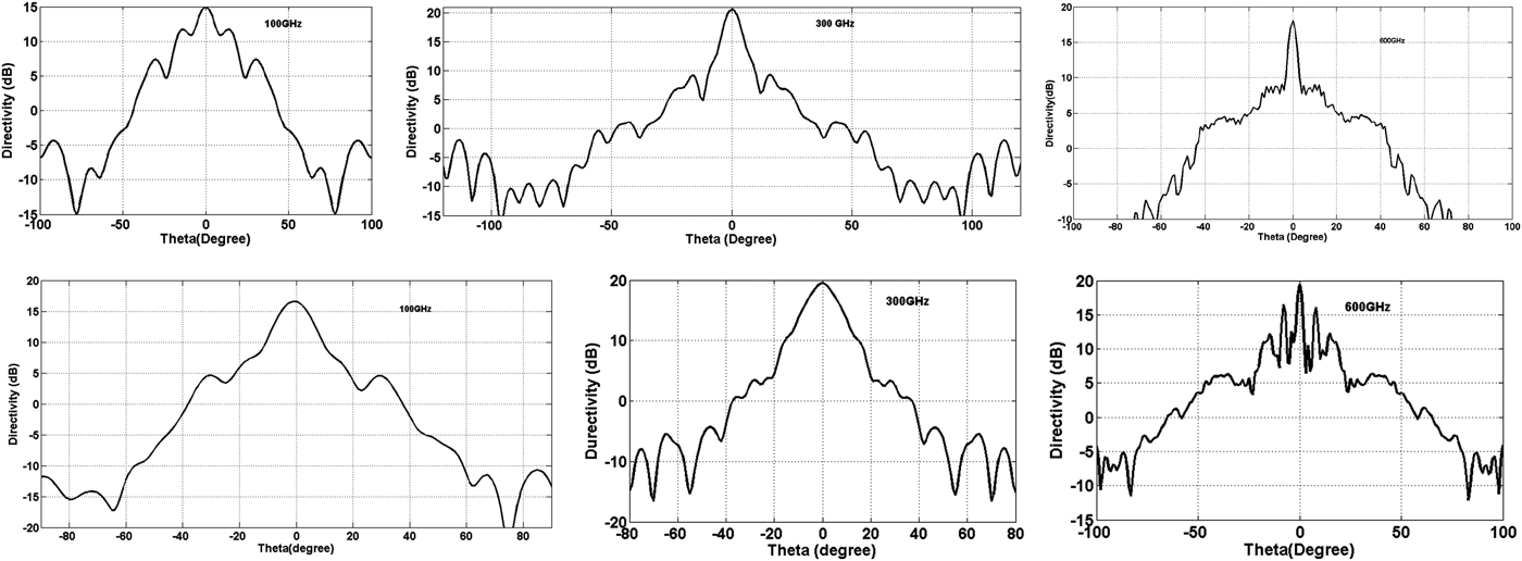
Radiation patterns of both dipole antennas with hemisphere lens of radius 7 mm at various frequencies f = 100, 300, 600 GHz are shown in Fig. 13(a) and 13(b). Narrowing of beam shape with frequency is quite clear in both antennas. Figure 13 depicts that for low frequency region both antennas radiate in broadside direction with few side lobes. While for high frequency region CL antenna showed more side lobes as compared to CBT. CBT antenna is found to maintain its beam shape at maximum frequency. On the other hand CL antenna has more side lobes at maximum frequency which can be attributed to internal reflections and deviation of the lens surface from nominal shape [Reference Semenov22].
Radiation pattern at 100, 300, and 600 GHz (a) CBT (b) CL antennas with R = 7λ with L/R = 0.45.
V. SECTION IV
Evaluation of CP behavior of designed dipole antennas mounted on lens is carried out in this section. CP behavior of lens coupled CBT antenna is presented in this section. Other dipole antenna has also been studied and found to follow the same pattern. Figure 14 depicts axial ratio (AR) versus elevation angle of the on axis element of lens structure. It is quite evident from figure that antenna preserves its CP behavior even in the presence of dielectric lens. CP behavior remains unaffected at main lobe direction. This astonishing result is attributed to rotationally symmetric property of lens and parallel and perpendicular transmission coefficients are constant along circular boundary resulting in E // and E ⊥ along circular boundary contribute to CP of on axis pattern.
AR versus elevation angle of on axis element.
AR versus frequency curve of on axis element is shown in Fig. 15. It covers a band of 250–600 GHz for center element possessing almost similar CP bandwidth as that of planar configuration. Minimum value of AR of 0.3 dB is attained at 500 GHz. Off axis element's CP behavior is also studied carefully. AR versus frequency curve of elements placed at different off axis places are shown in Fig. 15 which shows with increase of off axis distance CP property continue to degrade. Element placed at 0.5 mm apart from center has CP bandwidth of 290–600 GHz. While further displacement from center causes a sudden decrease in CP bandwidth to 280–320 GHz. Next element placed at 1.5 mm possesses CP only at 300 GHz. This decreasing trend of CP is caused by E Θ and E ø variation in lens due to more internal reflections at off axis positions. Maximum allowed off axis displacement on basis of CP is found to be 1.5 mm. Therefore CP array can be designed on basis of these conclusions with best performance.
AR versus frequency of on axis and off axis elements.
VI. CONCLUSION
Numerical investigations of broadband, CP novel dipole antennas CL and CBT mounted at back of low dielectric lens is carried out in presented work. Performance analysis of both dipole antennas mounted on lens in terms of array behavior, off axis element behavior, lens dimension's variation for improvement of radiation characteristics and CP behavior and depolarization of off axis elements has been presented. FPA of CBT and CL antennas analysis has shown off axis behavior of both antennas and useable area found to be almost 3 × 3 mm and 3.5 × 3.5 mm for CBT and CL, respectively, with arrays of pixels 12 × 12 for CBT and 6 × 6 for CL antenna at 300 GHz. Element spacing of 0.5 mm and 0.7 mm is found to be most appropriate for getting uniform radiation patterns. This spacing and compact dimensions of designed dipoles resulted into densely packed FPA as compared to any conventional CP broad band antenna which is normally bulky and occupied more space resulting into focal low resolution due less number of array elements. Lens dimensions optimization to improve radiation performance showed radius variation of lens helped to improve directivity and as well as side lobe level to improve resulting in uniform patterns. Extension length selection for proposed design has been optimized to get better directivity. The most appropriate value of L/R is found to be 0.45. CP diversity of lens coupled antennas is observed. For on axis element CP behavior of antenna is unaffected by lens presence and 3 dB AR bandwidth of central element is found to be 250–600 GHz. Depolarization tendency of off axis elements is also observed. It is found that CP property of antenna decrease with increase on off axis displacement and for the designed antennas it is found to lose its CP property after displacing more than 1.5 mm.
Amna Mir received her master's degree in Physics from the University of the Punjab, Pakistan. She is currently doing her Ph.D. in Electronics from School of Electronic Engineering, Beijing University of Posts and Telecommunications. Her Ph.D. thesis concerns designing and characterization of terahertz detection schemes.
Junsheng Yu got his Ph.D. degree from the University of Electronic Science and Technology of China in 1990. He is currently a Professor in the School of Electronic Engineering, Beijing University of Posts and Telecommunications. His research interests are focused on RFID systems, measurement techniques, and also THz technology. He is an expert of the national high technology research and development program
Xiaodong Chen, Ph.D., SMIEEE, MIET, is a Professor of Microwave Engineering in School of Electronic Engineering and Computer Science. He is the Director of the BUPT-QMUL Joint Research Lab in Beijing. He holds Visiting Professorships at the University of Westminster (UK), Beijing University of Posts and Telecommunications (BUPT) and the University of Electronic Science and Technology of China.
Ishtiaq Ahmad received his Ph.D. degree from the University of Posts and Telecommunications Beijing in 2014, M.Sc. degree from the University of Engineering and Technology Peshawar in 2004. Currently, he is serving as Assistant Professor at University of Lahore Pakistan.