
Introduction
Since their discovery by Iijima in 1991 [Reference lijima1], carbon nanotubes (CNTs) have attracted comprehensive interest in scientific community [Reference Mahanthesha, Srinivasa and Mohankumar2, Reference Zhou, Yamaguchi, Kikuchi, Nomura and Kawasaki3] and have been regarded as ideal nano-reinforcements of ceramic and polymer composites. In recent years, CNTs have also aroused widespread interest in the field of metal matrix composites (MMCs) due to their outstanding properties [Reference Zhang and Chen4]. However, due to the large specific surface area, CNTs as reinforcements of MMCs are prone to agglomerate under Van der Waals force [Reference Li, Xiong, Wang, Yan, Yang, He, Chen, Wang, Zhang and Dai5]. In addition, due to the poor wettability between untreated CNTs and metal matrix, only mechanical interfaces can form between them with no interfacial interaction [Reference Bakshi, Lahiri and Agarwal6, Reference Franklin and Salmeron7]. Therefore, the attainment of homogeneous dispersion of CNTs in metal matrix and the formation of strong interfacial bonding between CNTs and metal matrix are two critical issues for the development of CNT-reinforced MMCs.
By changing the surface conditions of CNTs, the interface microstructure can be optimized, thus improving the dispersion uniformity of CNTs in the metal matrix and the interfacial bonding strength between CNTs and the matrix [Reference Kim, Cha, Gemming, Eckert and Hong8, Reference Guo, Song, Yi, Ni, Shen and Du9, Reference Cho, Kikuchi and Kawasaki10, Reference Wang, Zhang, Zhang, Hu, Li and Cheng11]. In general, acid treatment is a common method used to change the surface conditions of CNTs. By acidizing CNTs in a mixed sulfuric/nitric solution, oxygen-containing functional group, including atomic oxygen and carboxyl and hydroxyl groups, can form on the surface of CNTs [Reference Zhou, Bang, Kurita, Miyazaki, Fan and Kawasaki12]. These functional groups can cause an increase in hydrophilicity at the CNT surface and create a highly active surface and thereby contributing to bind adsorbed metal atoms more strongly on the CNT surface [Reference Hannulaa, Aromaaa, Wilsona, Janasb, Koziolb and Lundströma13]. By using molecular-level mixing process, oxygen atoms were reported to present at the CNT–Cu interface in the nanocomposite fabricated by Kim et al. [Reference Kim, Cha, Gemming, Eckert and Hong8]. The results showed that oxygen atoms were helpful for the strong bonding between CNTs and copper matrix. In addition, precoating the CNTs with Cu and Ni films is also used in changing the surface conditions of CNTs, which is an effective method to improve the dispersion uniformity of CNTs in metal matrix through enhancing the wettability and compatibility between CNTs and metal matrix [Reference Lee, Sim, Kim, Moon, Cho and Baik14, Reference Wang, Zhang, Hu, Wang, Li, Korznikov, Zhao, Liu, Liu and Kang15, Reference Maqbool, Hussain, Khalid, Bakhsh, Hussain and Kim16, Reference Khabazian and Sanjabi17], thereby effectively improving the properties of composites.
To achieve better density and distribution/alignment of CNTs in the MMCs, many researchers have used post-sintering deformation. Zhang et al. [Reference Zhang, Wei, Li, Fu and Geng18] have investigated the effect of hot extrusion and heat treatment on the interface bond strength in the SiCw + CNTs/6061Al hybrid composites. After hot extrusion, the composite showed enhanced tensile strength due to the improvement of interfacial bond strength between CNTs and Al. Rolling is another way to align CNTs in the metal matrix. Xue et al. [Reference Xue, Wang, Zhao, Xu, Qi and Fe19] prepared CNT/Cu composite by spark plasma sintering (SPS) and hot rolling, and fully dense composites with homogeneous CNT distribution were obtained. Post-sintering deformation has been found to break CNT clusters and result into more homogeneous dispersion of CNTs [Reference Kim, Cha, Hong and Hong20, Reference Liao, Tan and Sridhar21].
In this article, acid-treated CNTs (AT-CNTs) precoated with Ni coatings were used to enhance the distribution uniformity and the interfacial bonding between CNTs and copper matrix. A combination of SPS and subsequent cold rolling was used to fabricate the copper matrix composites. The goal of the present work was to optimize the distribution uniformity of CNTs and interface microstructure by using the functionalized CNTs. The effects of Ni-coated CNTs and uncoated CNTs on the mechanical properties of composites were also investigated.
Results
Structure of the powders
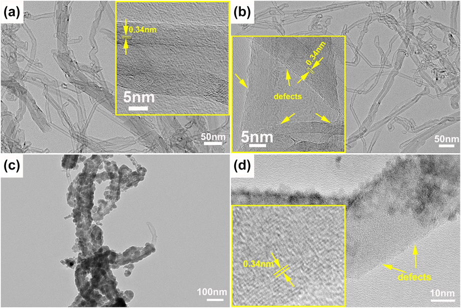
The morphologies of CNTs with different surface conditions were monitored by transmission electron microscopy (TEM). As shown in Fig. 1(a), the raw CNTs have slender shape with regular walls and hollow central channel. The outermost wall of the raw CNTs is a clean graphene layer without amorphous carbon layer. The walls are continuous and parallel to each other along the axial direction, showing high crystallinity.
TEM morphologies of CNTs with different surface conditions: (a) raw CNTs, (b) AT-CNTs, (c) Ni-CNTs, and (d) high-resolution TEM image of Ni-CNTs.
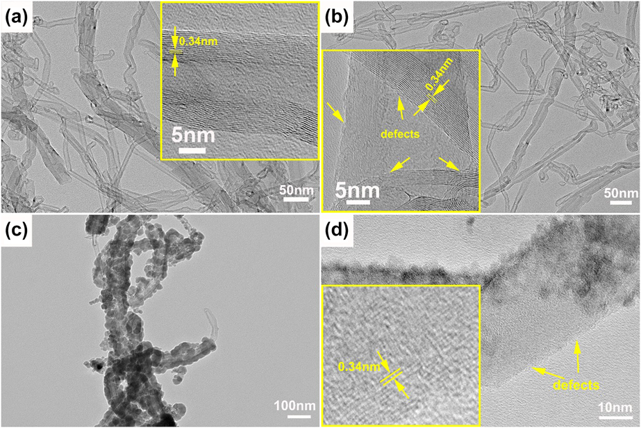
Acid treatment is most frequently employed to functionalize the surface of CNTs and to introduce nanoscale defects [Reference Zhou, Bang, Kurita, Miyazaki, Fan and Kawasaki12]. Overlapping and dangled graphene sheets and notch-type defects are observed on the sidewalls of AT-CNTs in Fig. 1(b) after acid treatment. Note that the disordered sites exist only on the outer walls of AT-CNTs and the inner walls still maintain unbroken structure with high crystallinity. Through the acid treatment, the C–C bonds can be opened, and accordingly, oxygen-containing functional groups, like carboxyl and hydroxyl, were introduced to the surface of CNTs [Reference Hannulaa, Aromaaa, Wilsona, Janasb, Koziolb and Lundströma13].
Figures 1(c) and 1(d) show the TEM images of CNTs with Ni coatings. As shown, Ni coatings were formed on the surface of CNTs and the coating is discontinuous on the surface of CNTs. It is obvious in Fig. 1(d) that some areas of the CNTs were still not covered by Ni particles, showing the surface characteristics of AT-CNTs. Figure 1(d) also shows that the inner walls of CNTs after coating still maintained an integrated graphite structure.
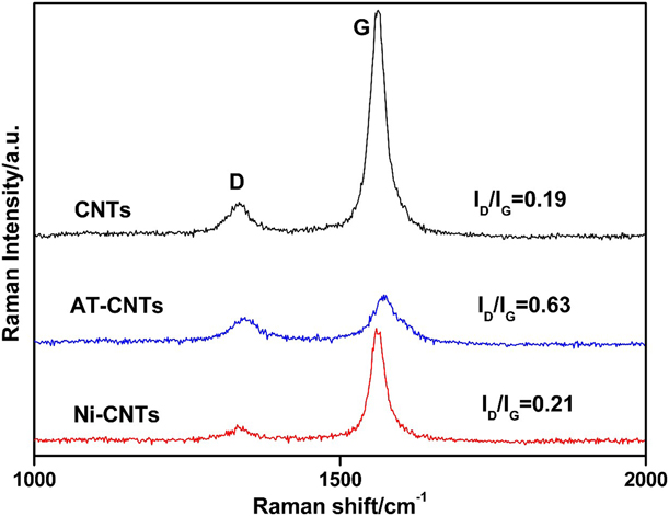
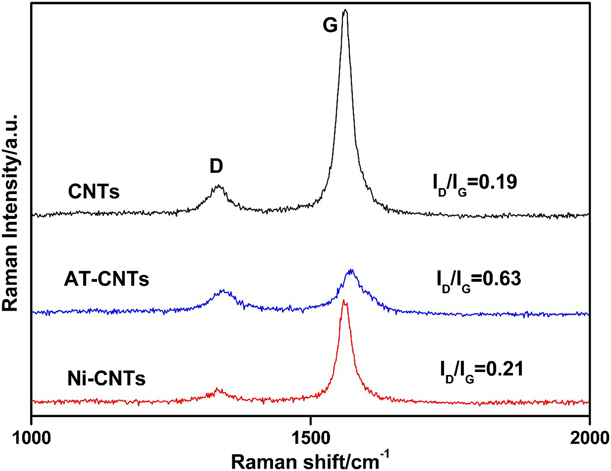
Raman I D/I G intensity ratio is used to qualitatively examine the surface defect level of the reinforcements [Reference Dresselhaus, Jorio, Souza Filho and Saito22], as shown in Fig. 2. Compared with raw CNTs, the increased I D/I G of AT-CNTs confirmed the successful introduction of surface defects. Because CNTs were covered by Ni coatings, the intensity of both the D and G bands in the mixed powders was significantly reduced. In addition, the decreased I D/I G of Ni-CNTs compared with that of AT-CNTs also suggested that the surface defects on AT-CNTs were covered by the Ni coatings.
Raman spectra of the raw CNTs, AT-CNTs, and Ni-CNTs.
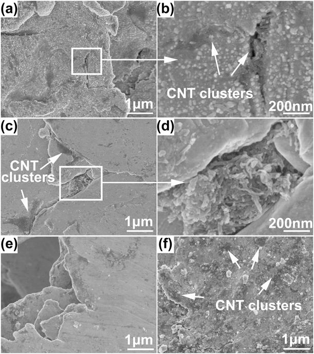
The dispersion state of CNTs on pretreated Cu powders after ball milling for 10 h is shown in Fig. 3. Generally, acid treatment can improve the wettability of the CNTs with metal matrix. As shown in Fig. 3(a), the AT-CNTs are distributed uniformly on the Cu matrix in Cu-1 vol% CNTs composite powders, and the tubular structure of CNTs was still retained after ball milling. However, CNT clusters can also be observed at where the powders were welded [Fig. 3(b)]. It can be seen from Figs. 3(c) and 3(d) that when the content of CNTs increased to 2 vol%, the agglomeration area of CNTs increased significantly. As revealed by Fig. 3(e), after coating with Ni, CNTs were embedded into the Cu powders and no obvious naked CNTs were observed on the surface of Cu powders. The improved dispersion uniformity of CNTs can be attributed to the enhancement of wettability between Ni-CNTs and Cu matrix. CNT clusters can still be observed in Cu-2 vol% Ni-CNTs composite powders [Fig. 3(f)], exhibiting a more uniform dispersion with significantly reduced area compared with that in Cu-2 vol% CNTs composite powders.
SEM images of the composite powders: (a, b) Cu-1 vol% CNTs; (c, d) Cu-2 vol% CNTs; (e) Cu-1 vol% Ni-CNTs; and (f) Cu-2 vol% Ni-CNTs.

Microstructure of the composites
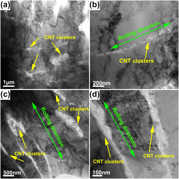
Figure 4 shows the TEM micrographs of the composites reinforced by different content of Ni-CNTs. As shown in Figs. 4(a)–4(d), the density of CNTs in Cu matrix obviously increased when the content of Ni-CNTs increased from 1 vol% to 2 vol% and the distribution of Ni-CNTs in Cu-1 vol% Ni-CNTs composite was more homogeneous. The TEM images also indicate that the agglomeration of Ni-CNTs has been transformed into ribbons aligning along the rolling direction. During the rolling process, the Ni-CNT clusters were forced to extend along the rolling direction due to the plastic flow of the Cu matrix. From the further magnified TEM image of Fig. 4(d), the shape of Ni-CNTs became irregular, which was caused by the distortion or fracture during the ball milling process.
TEM images of the composites reinforced with Ni-coated CNTs after rolling: (a, b) Cu-1 vol% Ni-CNTs and (c, d) Cu-2 vol% Ni-CNTs. The two composites possess different dispersion of CNTs.
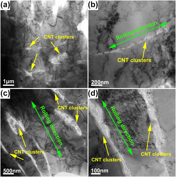
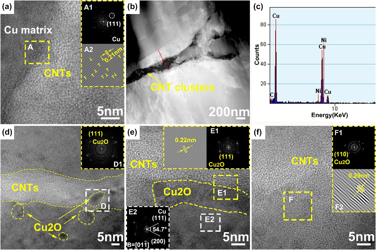
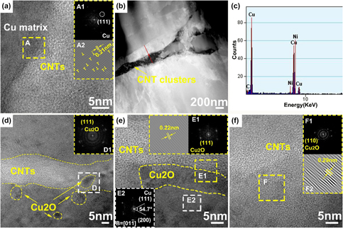
Figure 5 is the TEM images of the interface between the Ni-CNTs and Cu matrix in 1 vol% Ni-CNT/Cu composites, showing several different interface structure. As shown in Fig. 5(a), a clean and clear interface existed between the Ni-CNTs and Cu matrix and no visible physical gap was observed along the interface. The fast Fourier transform (FFT) images [Fig. 5(A1)] show the clean diffraction spots of Cu. This might suggest the good wettability between the AT-CNTs and the Cu matrix. A few dislocations can be observed in the Cu matrix near the interfaces [“T”-shaped symbols in the inverse FFT (IFFT) images of Fig. 5(A2)], which were likely to originate from the noticeable internal stress caused by the mismatch of thermal expansion coefficient between CNTs and Cu matrix [Reference Zhang and Zhan23]. These misfit dislocations were proven to be conductive to the promotion of interface adhesion [Reference Chu, Wang, Wang, Li, Geng, Huang and Zhang24].
TEM images of the interface between Ni-CNTs and Cu matrix in 1 vol% Ni-CNT/Cu composites: (a) clean CNT–Cu interface; (b, c) the line scanning under STEM; and (d–f) interface with Cu2O nanoparticles.
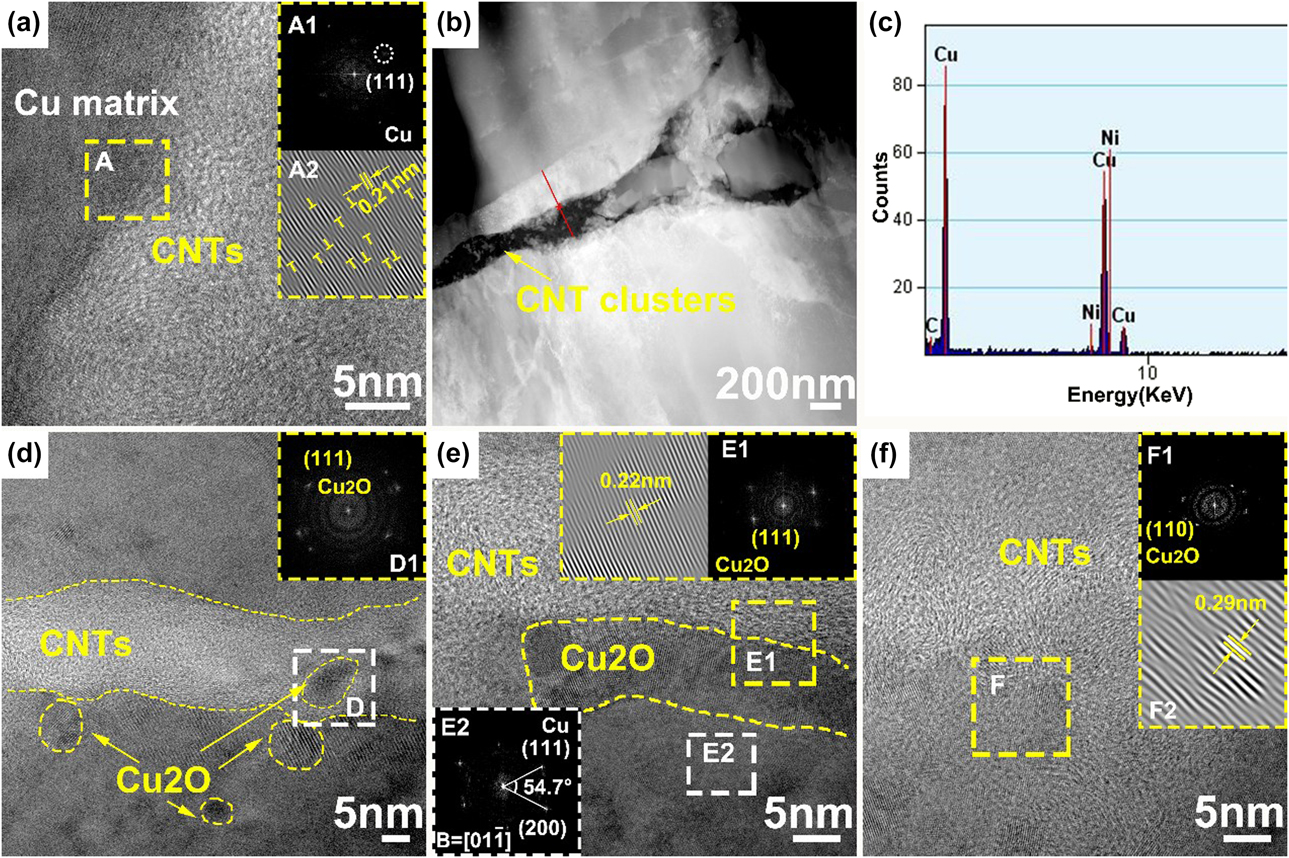
Figure 5(b) shows the low-magnification scanning TEM (STEM) images at the Ni–CNT–Cu interface and the element distribution at the interface zone was identified by the line scanning under STEM mode. The line scan results [Fig. 5(c)] show that Ni existed around the interface. Generally, Ni coatings can greatly improve the wettability of CNTs with the Cu matrix, thereby improving the interfacial bonding strength.
Another type of interface between the Ni-CNTs and Cu matrix was also observed. As shown in Figs. 5(d)–5(f), small nanocrystals were observed at the interface between Ni-CNTs and Cu matrix. These nanocrystals tend to form at the defect sites of Ni-CNTs not covered by Ni nanoparticles, which closely connected the CNT with the Cu matrix. Based on the FFT and IFFT patterns of the marked areas, the interplanar spacing of these lattice fringes is measured to be ∼0.22 nm and ∼0.29 nm, corresponding to the d-spacing of (110) and (111) planes of cubic Cu2O (lattice parameter: a = 0.427 nm [Reference Chu, Wang, Li, Wang, Huang and Zhang25]). The high-resolution TEM image also shows that the boundary of CNT–Cu2O–Cu interface is not clear, but with a gradual transition from the Cu2O with screwy lattice planes to the CNT and Cu matrix with disordered atom arrangement. Because the chemical reaction usually had course morphologies [Reference Franklin and Salmeron7], the observed interface was the place where nanocrystal Cu2O formed. Generally, the interface between CNTs and Cu matrix is weak mechanical bonding due to the lack of wetting and interaction between them. The presence of dislocations and Cu2O at the interface between CNTs and Cu matrix can optimize the interface bonding condition.
Based on the above TEM observations, several different types of interfaces existed between Ni-CNTs and Cu matrix: clean interface with no visible physical gaps, interface with Ni between the CNTs and Cu matrix, and interface containing interfacial Cu2O nanoparticles.
Mechanical properties and fracture surfaces of the composites
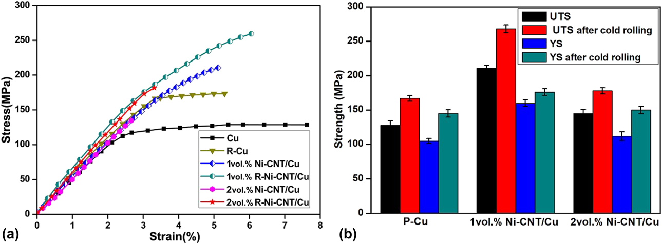
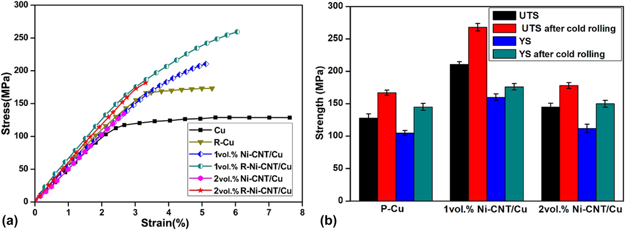
Figure 6 shows the tensile stress–strain curves of the pure Cu and the composites with different Ni-CNT content fabricated by SPS before and after rolling. Before rolling, both the yield strength (YS) and the ultimate tensile strength (UTS) of the composites were obviously improved compared with Cu but showed lower ductility. The lower ductility may originate from the weaker interface bonding and residual voids at the interface after SPS, which may become the source of crack initiation during mechanical response, leading to premature fracture. The YS and UTS of 2 vol% Ni-CNT/Cu are obviously lower than those of 1 vol% Ni-CNT/Cu, which could be attributed to the agglomeration of Ni-CNTs in the Cu matrix due to the increased volume content. After rolling, the strength of 1 vol% Ni-CNT/Cu composite and the pure Cu increased, while the strength of 2 vol% Ni-CNT/Cu composite decreased with lower elongation. It can be seen that the YS and UTS of 1 vol% rolled Ni-CNT/Cu (R-Ni-CNT/Cu) composite reached to the maximum values of ∼180 MPa and ∼261 MPa, respectively. It is worth noting that the elongation of 1 vol% Ni-CNT/Cu composite also increased from about 5% before rolling to about 6.2% after rolling. This phenomenon can be attributed to the improvement of interfacial bonding and dispersion uniformity of CNTs after rolling, that is, rolling can eliminate the possible pores at the interface and break up the aggregation of CNTs to make the distribution of CNTs more uniform in the Cu matrix. With the increase in CNT content, the agglomeration degree of CNTs in the Cu matrix increased, which made the composites unable to achieve densification even after rolling, which greatly reduced the mechanical properties of the composites.
(a) The tensile stress–strain curves of Cu and the composites before and after rolling. (b) The UTS and YS of Cu and the composites before and after rolling.
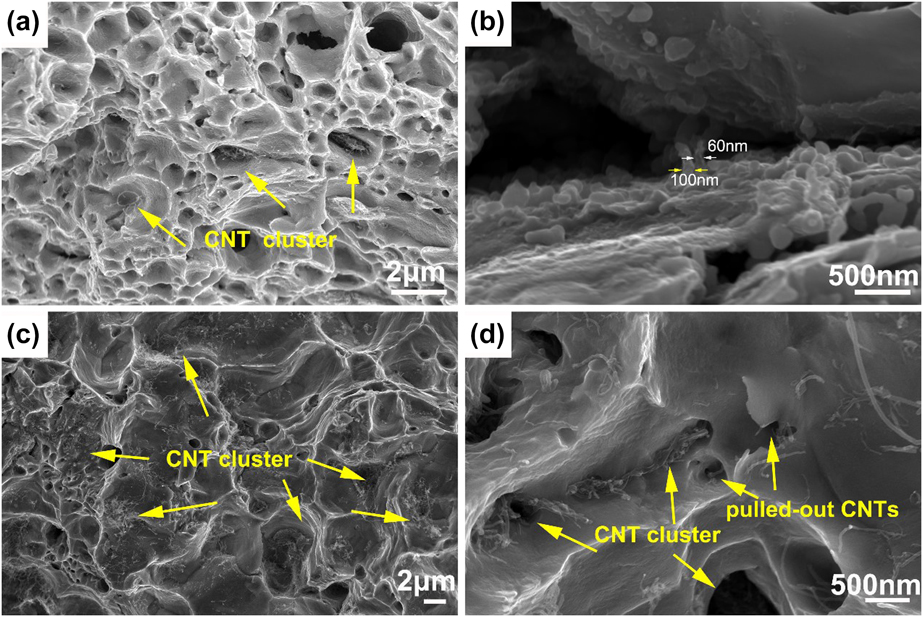
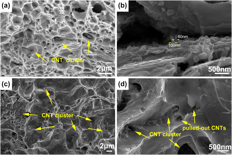
The fracture morphologies of the composites reinforced with different content of Ni-CNTs after rolling are shown in Fig. 7. Dimples [Figs. 7(a) and 7(c)] can be observed on the fracture surfaces of all the composites, indicating that the Cu matrix had experienced substantial plastic deformation before tensile failure. Pulled-out Ni-CNTs can be observed on the fracture surfaces of the composites [Figs. 7(b) and 7(d)], suggesting the load had been transferred from Cu matrix to the reinforcements during tensile tests. It is worth noting that the diameter of the pulled-out CNTs [Fig. 7(b)] are bigger than the average diameter of the CNTs, and this may be due to that the surface of CNTs was covered by a Cu layer, which indicated that CNTs and Cu matrix were well bonded at the interface. In addition, obvious CNT clusters [Fig. 7(d)] were also observed on the fracture surfaces of the composites reinforced with 2 vol% of Ni-CNTs. The agglomeration of reinforcements will severely limit the strengthening effect [Reference Zhang, Shi, Liu, He, Ma, Li, Li, Zhao and He26, Reference Yang, Weng, Zhu, Zhang, Fan and Zhang27].
SEM images of the fracture surfaces of the composites with different magnifications: (a, b) 1 vol% Ni-CNT/Cu and (c, d) 2 vol% Ni-CNT/Cu.
Discussion
Interface in Ni-CNT/Cu composites
The interfacial bonding strength usually determines the mechanical properties of the CNT-reinforced MMCs, which is strongly affected by the interaction between CNTs and metal matrix [Reference Tsai and Jeng28]. The interfacial bonding strength is greatly influenced by the ways of interface bonding. Generally speaking, only weak mechanical interface could be formed between the Cu matrix and untreated CNTs due to the poor wettability between them. Through surface coating the CNTs with Ni films, even if only partially Ni plated, the wettability between CNTs and Cu matrix can be obviously improved, thus contributing to the distribution uniformity of CNTs and better interface bonding [Reference Chen, Tao, Yi, Liu, Bao, Li, Tan and You29]. However, the improvement of interface bonding through Ni coatings is limited, because effective chemical bonding is still not achieved at the interface.
Acid treatment is the most frequently employed method to enhance the chemical activity and hydrophilicity of CNTs by introducing nanoscale defects and functional groups [Fig. 1(b)] onto the surface of CNTs, which is helpful to optimize the interface bonding between CNTs and metal matrix [Reference Guo, Zhang, Cen, Chen, Wang, Song, Ni, Yi, Shen and Du30]. In addition, by opening the outer walls of CNTs through acid treatment, the applied load is expected to transfer to the inner walls, so that CNTs can better play the role of load transfer, thus further improving the load transfer efficiency of CNTs. Defects on the surface of AT-CNTs could increase the roughness at the interface, thereby improving the mechanical bonding strength [Reference Guo, Song, Yi, Ni, Shen and Du9]. The AT-CNTs also possess plenty of oxygen-containing functional groups, such as hydroxyl and carboxyl [Reference Khurram, Munira, Zhang, Lin, Li and Wen31]. These functional groups on AT-CNTs have been proved to have positive impacts on the interfacial strength [Reference Park, Kim, Kim, Han, Kim and Lee32]. With the participation of residual oxygen in the functional groups, the CNT–oxygen–copper bonding can form at the interface with different structures. Formation of chemical bonding between CNTs and metal matrix is considered to be the most important factor to obtain a strong interface. In some of the researches [Reference Kim, Cha, Gemming, Eckert and Hong8, Reference Kim, Eckert, Liu, Park, Lim and Hong33], no intermediate compounds found at the CNT–Cu interface, except for the formation of copper–oxygen bonds. While in other researches, such as in the study of Zhang and Cheng et al. [Reference Zhang, Shi, Liu, He, Ma, Li, Li, Zhao and He26, Reference Kim, Eckert, Liu, Park, Lim and Hong33, Reference Cheng, Bao, Yi, Li, Tao, Liu, Tan and You34], copper oxides were found at the CNT–Cu interface by using functionalized CNTs as reinforcements. Our previous study has indicated that [Reference Chen, Tao, Liu, Bao, Li, Li and Yi35] the formation of Cu2O can occur when the surface of Cu comes into contact with a relative oxygen-rich environment of CNTs (Fig. 5), like the defect sites on the sidewall of CNTs. During consolidation process, strong Cu–oxygen bonds could form through the interaction between the CNTs and Cu matrix. The in situ formed Cu2O at the interface could be regarded as the interphase between CNTs and Cu matrix. These interphases can link the inner walls of CNTs at the defect sites and act as bridges between CNTs and Cu matrix [Reference Zhang and Zhan36, Reference Saba, Sajjadi, Haddad-Sabzevar and Zhang37], resulting in high load transfer efficiency.
Effect of interface on the mechanical properties
The mechanical properties of CNT-reinforced MMCs depend on the bonding strength of the interface, which is strongly influenced by the interaction between CNTs and metal matrix. On the basis of the experimental results, the interface bonding strength of CNTs–Cu composites can be generated from two aspects, namely, through mechanical bonding and chemical bonding. As shown, the interfacial Cu2O can closely connect the Cu matrix and CNTs. The excellent properties of the CNTs are futile to improve the performance of the Cu/CNTs composite if the applied load cannot be transferred from the Cu matrix to them. The contribution of the interface in composites containing fiber-shaped reinforcements can be analyzed by shear lag model [Reference Zhang, Mai, Huang and Shi38, Reference Ryu, Cha and Hong39, Reference Chen, Wu, Xu and Xu40, Reference Chen, Kondoh, Imai, Umeda and Takahashi41].
 $${\sigma _{{\rm{YS}}}} = {\sigma _{\rm{M}}}\left[ {{V_{{\rm{CNTs}}}}\left( {{{{S_{{\rm{eff}}}}} \over 2} + 1} \right) + {V_{\rm{M}}}} \right]\quad ,$$
where σYS is the YS of the composite; σM is the YS of the matrix (110 MPa); V M and V CNTs are the volume fractions of Cu matrix and the reinforcement (CNTs), respectively; and S eff is the effective aspect ratio of the reinforcements. S eff is defined as follows:
 $${S_{{\rm{eff}}}} = S\;{\cos ^2}\;\theta + \left( {1 - {4 \over {3\pi }}} \right)\left( {1 + {1 \over S}} \right){\sin ^2}\;\theta \quad ,$$
where θ is the misorientation angle of the CNTs with respect to the tensile direction in the composite, and θ is 0 when the CNTs are perfectly aligned along the tensile direction. Owing to the rolling process, most of the CNTs in the Cu matrix were along the rolling direction (as shown in Fig. 4), and the S eff can be assumed as S(S = l/d), where d is the diameter of the CNTs (15 nm) and l is initial length of all the applied CNTs (2 μm). Suppose the initial aspect ratio of the CNTs was maintained after the fabrication process, the theoretical YS of 1 vol% Ni-CNT/Cu composite is calculated to be 183 MPa based on the generalized shear-lag model. In shear-lag theory, the improved strength contributed by load transfer can be obtained through ΔσLT = σYC − σM, and the interfacial strength τ can be obtained by the following equation:
 $$\tau = {{d\Delta {\sigma _{{\rm{LT}}}}} \over {{V_{{\rm{CNT}}}}l}}\quad .$$
According the above analysis, the experimental YS of 1 vol% Ni-CNT/Cu composite (180 MPa) is nearly the same as the theoretical value, which is believed to be the contribution of uniform dispersion of Ni-CNTs and strong interface bonding between CNTs and Cu matrix due to the formation of Cu2O. It can be seen from Eq. (3) that τ decreased with the increase in volume fractions of CNTs, which is consistent with the observed phenomenon in our experiment (Fig. 6).
Based on molecular dynamics, the sliding mechanism of Ni-coated CNTs against copper matrix is much more like a kind of friction sliding and directly related to the CNTs and copper matrix, which is helpful for improving the mechanism properties of the composites [Reference Duan, Li, Hu and Wang42]. In addition, the acid treatment can introduce defects on the surface of CNTs and provide the nucleation position for the formation of Cu2O, which can effectively improve the interface bonding between CNTs and Cu matrix.
Conclusion
In this study, AT-CNTs were partially covered with Ni coatings through electroless deposition, and Ni-CNT/Cu composites were fabricated through ball milling, SPS, and subsequently cold rolling. Compared with uncoated CNTs, the distribution uniformity of Ni-CNTs in Cu matrix obviously increased. Cu2O nanoparticles were in situ formed at the CNT–Cu interface, which also contributed to the interface bonding. After rolling, the distribution of Ni-CNTs transformed into ribbons aligning along the rolling direction. The YS of rolled Ni-CNT/Cu composite was 180 MPa, which was nearly the same as the theoretical value. The UTS of rolled Ni-CNT/Cu composite was 261 MPa, which was 24.3% higher than that of unrolled Ni-CNT/Cu composite. As the content of Ni-CNTs increased from 1 to 2 vol%, the UTS of the composites decreased obviously, which can be attributed to the agglomeration of reinforcements.
Materials and methods
Preparation of CNT/Cu composites
The CNTs (Chengdu Institute of Organic Chemistry Co. Ltd., Chengdu, China), with average outer diameter of 10–20 nm, were synthesized by means of catalytic chemical vapor deposition. The CNTs were acid treated by a H2SO4/HNO3 mixture (3:1, v/v) in the ultrasonic bath for 10 h at 338 K. The suspension was scoured with deionized water until pH to be neutral before collecting on the filter paper. The AT-CNTs were completely dried in an oven at 333 K for 24 h. After pretreatments, the electroless deposition method was used to deposit a layer of Ni on the surface of the pretreated CNTs (Ni-CNTs).
Spherical Cu powders (particle size 4–7 μm, purity 99.95%; Shanghai Naiou Nano Science and Technology Co., Ltd., Shanghai, China) and CNTs are ball milled together in pure ethanol with a rotation rate of 300 rpm for 10 h. For comparison, the volume fraction of different CNTs in the powder mixtures was 1 and 2 vol%. After filtration, vacuum drying, and reduction, composite powders were obtained. For reduction process, the composite powders were annealed in an Ar–5% H2 atmosphere at 523 K for 10 h using a high-temperature vacuum sintering furnace (ZTY-40-20; Tianjin Hengchanglong electric furnace manufacturing Co., Ltd., Tianjin, China).
The reduced composite powders were consolidated by SPS (SPS-10T-5; Shanghai Chen Hua Furnace Co., Ltd., Shanghai, China) at 1073 K for 10 min with pressure of 50 MPa under a vacuum of ∼5 Pa. The heating rate was 100 K/min. All samples were cold rolled after sintering, and the rolling reduction was 20%.
Characterization tests
A field-emission scanning electron microscopy (Nova Nano-450, FEI, Portland, Oregon) was used to observe the morphologies of the composite powders, composites, and fracture surface. The interface microstructures of the composites were characterized by TEM (Tecnai G2 TF30 S-Twin, FEI, Portland, Oregon). The tensile properties of the composites were measured by a mechanical tester (AG-X-100KN; SHIMADZU, Kyoto, Japan) with a crosshead speed of 0.1 mm/min. Vickers microhardness of the samples was measured using an MC010 microhardness analysis system (Shanghai Microcre Light-Machine Tech Co., Ltd., Shanghai, China) with a load of 0.49 N applied for 15 s.
Acknowledgments
The authors acknowledge the support from the National Natural Science Foundation of China (NSFC) under Grant Nos. 51561014, 51864029, and 51861014. The authors also gratefully acknowledge the supports from the Science Foundation of Yunnan Provincial Education Department (No. 2016CYH08) and the Science Foundation of the Yunnan Provincial Science and Technology Department (No. 2017HC033).