1. INTRODUCTION
As a dead-reckoning navigation method, the Strapdown Inertial Navigation System (SINS) can track the attitude, velocity and position of a vehicle by numerical integration of the inertial sensors’ measurements (Titterton and Weston, Reference Titterton and Weston2004). To establish the initial value for integration, the SINS initial alignment process is of great importance because it will largely determine the subsequent navigation accuracy (Li et al., Reference Li, Tang, Lu and Wu2013a). Traditional initial alignment methods, usually consisting of coarse-alignment and fine-alignment stages, must be completed prior to vehicle movement (Savage, Reference Savage2000). Typically, the coarse-alignment phase is required to estimate the vehicle's heading to an accuracy of a few degrees and pitch/roll to a few tenths of a degree to allow the fine-alignment filter to operate in its linear region (Silson, Reference Silson2011). There are two obvious limitations in traditional alignment methods: firstly, keeping a vehicle stationary for alignment consumes time and space (Liu et al., Reference Liu, Xu and Li2014; Wang et al., Reference Wang, Fu, Xiao and Deng2012; Shin and El-Sheimy, Reference Shin and El-Sheimy2004), and can be dangerous on the battlefield where high manoeuvrability is required and secondly, the coarse-alignment phase consumes a certain period of time (typically 30 to 120 seconds) (Hu and Cheng, Reference Hu and Cheng.2014) but has no direct contribution to final alignment accuracy.
Handling the first limitation is particularly important for military applications. In order to enhance manoeuvrability and thus survivability, it is necessary to achieve high accuracy alignment within a short time whether the vehicle is static or moving. Many efforts have been devoted to high-accuracy in-motion alignment techniques, which always need external sensors to compensate the vehicle motions. A Global Navigation Satellite Systems (GNSS), most frequently the Global Positioning System (GPS), providing velocity and position directly in the geographic coordinate system, is widely used as an aiding source for in-motion alignment (Jiang et al., Reference Jiang, Xie and Weng2013; Kaygısız and Sen, Reference Kaygısız and Şen2015; Kubo et al., Reference Kubo, Fujioka, Nishiyama and Sugimoto2006; Wu and Pan, Reference Wu and Pan2013a; Reference Wu and Pan2013b). However, GNSS are vulnerable to jamming, blocking and spoofing, greatly affecting their availability and reliability (Chang et al., Reference Chang, He and Qin2016; Pan and Wu, Reference Pan and Wu2016; Liu et al., Reference Liu, Li, Fu and Liu2018). For the land vehicles of interest here, an odometer is the most commonly used velocity-aiding source for autonomous initial alignment (Xu et al., Reference Xu, He, Qin and Chang2017; Bimal and Joshi, Reference Bimal Raj and Joshi2015; Wu, Reference Wu2014). Since an odometer provides velocity along the vehicle body frame, odometer-aided in-motion alignment usually requires not only attitude determination but also velocity and position calculation (Chang et al., Reference Chang, Li and Xue2017). The existing odometer-aided alignment methods fall into three main categories: (1) nonlinear Kalman filter approaches (Bimal and Joshi, Reference Bimal Raj and Joshi2015; Wu, Reference Wu2014; Chang et al., Reference Chang, Li and Xue2017; Li et al., Reference Li, Wang, Lu and Wu2013b), which can tolerate a large initial misalignment angle and allow the vehicle to move without a stationary period, but suffer from redundant computation; (2) linear Kalman filter INS/odometer integration, which can easily achieve attitude, velocity and position in the alignment, while the only shortcoming lies in that a 30 to 120 seconds stationary period is still needed for coarse alignment; (3) multi-vector attitude determination in an inertial frame, which has been the most popular method over the last decade (Chang et al., Reference Chang, He and Qin2016; Jiang et al., Reference Jiang, Xie and Weng2013; Wu, Reference Wu2014), but the mounting angles and odometer's scale factor must be calibrated perfectly in advance to ensure attitude and position alignment accuracy, and the heading alignment result may deteriorate by the equivalent change rate of acceleration bias caused by a possible turn of the vehicle.
For the second limitation, a backtracking navigation scheme is a good solution to take full use of the coarse alignment time. The method uses the inertial frame alignment strategy as forward coarse alignment, followed by backtracking linear Kalman filter fine alignment based on the data computed in the coarse alignment process (Li et al., Reference Li, Wu, Wang and Wu2014; Reference Li, Wu and Lu2013c). In order to avoid the overshoot caused by error model switch, the traditional backtracking scheme and subsequent navigation is established in the inertial frame instead of the classical geographic frame (Li et al., Reference Li, Wu, Wang and Wu2014). As a non-local level frame mechanisation, navigation in the inertial frame cannot conform to land navigation usage habits and will bring new problems. The unstable height channel cannot be decoupled in the inertial frame, so the navigation results in all three channels will be contaminated, and it is also difficult to damp the altitude divergence by other sensors such as an atmospheric pressure altimeter.
In Dissanayake et al. (Reference Dissanayake, Sukkarieh, Nebot and Whyte1999), a real time, on-the-fly, roll and pitch alignment algorithm for SINS on land vehicles without external sensors was proposed, which was achieved by exploiting the Non-Holonomic Constraints (NHC) that govern the motion of a vehicle on a surface. Focusing on a low-accuracy Inertial Measurement Unit (IMU), this study does not take the heading alignment and mounting angles into account, so the positioning accuracy is limited. Inspired by Dissanayake et al. (Reference Dissanayake, Sukkarieh, Nebot and Whyte1999), we propose a novel in-motion alignment method based on NHC and a backtracking navigation scheme for land vehicles. The proposed method consists of two tightly coupled stages. First, in the coarse alignment process, double-vector attitude determination based on a second-order integral of specific force in the inertial frame is deduced, to approximately estimate the attitude at the very start of the alignment. Meanwhile, attitude quaternions and velocity increments are extracted and recorded with lower frequency. Second, the backtracking process uses the estimated initial attitude and stored data to accomplish the fine alignment by SINS/NHC integrated navigation based on a linear Kalman filter in the geographic coordinate system. The proposed method has several advantages as follows:
(1) The alignment can be accomplished autonomously without any external sensors except the initial position. The mounting angles can be automatically estimated, and the pre-calibration process is unnecessary.
(2) There is no need to keep a vehicle stationary for coarse alignment, allowing the vehicle to move once the initial position is available. All inertial sensor data are used in both coarse alignment and fine alignment, and it is equivalent to lengthening the alignment time which contributes to improvement of the alignment accuracy.
(3) The method cannot only align the attitude to high accuracy within limited time, but also determines the velocity and position with satisfactory accuracy at the end of the alignment.
(4) Without large storage or redundant computation such as nonlinear filters, this scheme is easy to use in real time applications. The backtracking fine alignment and subsequent navigation arranged in the geographic frame are convenient for practical land vehicle applications.
The rest of this paper is organised as follows. Section 2 describes the proposed in-motion alignment algorithm, including the overall alignment strategy, coarse alignment process in the inertial frame, backtracking navigation updating and SINS/NHC integrated fine alignment process. Section 3 presents the results and discussions of three land vehicle in-motion alignment tests. Conclusions are drawn in Section 4.
2. PROPOSED ALIGNMENT ALGORITHM
In this paper, basic coordinate systems are defined as follows: the local level East-North-Up (ENU) geographic coordinate is chosen as the navigation frame, denoted by n-frame. The IMU b-frame is implicitly predefined by the sensitive axes of inertial sensors with axes pointing right, forward, and upward, respectively. The e-frame denotes the Earth-Centred Earth-Fixed (ECEF) reference frame, and the m-frame is the vehicle frame aligned with right-forward-up vehicle body axes.
2.1. In-motion alignment scheme
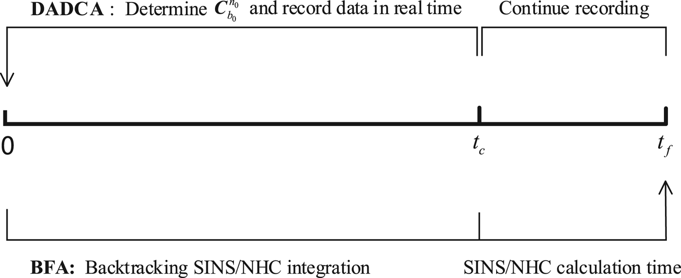
At the very start of alignment, the vehicle is static, and the initial velocity can be regarded as zero. Once an initial position is available, the SINS can start alignment and the vehicle is allowed to move immediately without a requirement for a specified stationary time. In order to accomplish accurate in-motion alignment without an external auxiliary sensor, this paper makes a combination of two tightly coupled alignment stages: real-time Double-vector Attitude Determination Coarse Alignment (DADCA) and Backtracking Fine Alignment (BFA).
As shown in Figure 1, the DADCA process is used to determine a rough initial attitude matrix  ${\bi C}_{b_{0}}^{n_{0}}$, which denotes the orientation of the b-frame with respect to the n-frame at the very start of alignment. Meanwhile, attitude quaternions and velocity increments extracted in the DADCA process are recorded with low frequency (1 Hz in this paper). With no auxiliary information in the DADCA process, the required real-time velocity and position for coarse alignment are all approximated using the initial values which means that the vehicle's motion is temporarily omitted. The technique of second-order integral of specific force in the inertial space is deduced to suppress the motion interference. In the BFA process, the initial attitude matrix
 ${\bi C}_{b_{0}}^{n_{0}}$ and the recorded data are used to accomplish SINS/NHC integrated navigation based on a linear Kalman filter.
The proposed in-motion alignment scheme.

The time range of the DADCA process is [0, t c], while the recorded data from time zero to t f is used in the BFA process. The time interval [t c, t f], which is left for the navigation computer to execute the backtracking SINS/NHC filter, can be shortened to a few seconds with a high performance digital signal processor. It is obvious that almost all the sensor data in time [0, t f] is used not only in coarse alignment but in fine alignment as well, so there is no time wasted and it is beneficial in improving the alignment accuracy.
2.2. The DADCA process
2.2.1. Real-time coarse alignment
Assuming that the orientation of the IMU b-frame relative to the n-frame is unknown at start-up, we arbitrarily form the b 0- and n 0-frames by inertially fixing the b- and n-frames at the beginning of the alignment. Since both the b 0- and n 0-frames are fixed with respect to the inertial frame, the direction cosine matrix  ${\bi C}_{b_{0}}^{n_{0}}$ is constant (Silson, Reference Silson2011). According to the chain rule of the attitude matrix, the time-varying attitude matrix
 ${\bi C}_{b}^{n}(t)$ can be decomposed as (Gu et al., Reference Gu, El-Sheimy, Hassan and Syed2008; Wu et al., Reference Wu, Wu, Hu and Hu2011):
 $${\bi C}^n_b(t)={\bi C}^n_{n_0}(t){\bi C}^{n_0}_{b_0}{\bi C}^{b_0}_{b}(t)$$
where  ${\bi C}_{n_{0}}^{n}(t)$ represents the time-varying matrix of the n-frame relative to the inertial space as a function of the Earth rotation rate and position change relative to the Earth;
 ${\bi C}_{b}^{b_{0}}(t)$ represents the time-varying matrix due to the rotation of the b-frame relative to the inertial space as a function of inertial angular rates measured by the gyroscope and
 ${\bi C}_{b_{0}}^{n_{0}}$ represents the constant matrix between the initial b 0- and n 0-frames at t=0. The purpose of the DADCA process is to determine the initial constant matrix
 ${\bi C}_{b_{0}}^{n_{0}}$ instead of the time-varying attitude matrix
 ${\bi C}_{b}^{n}(t)$.
The navigation specific force equation in the n-frame is well known as (Qin, Reference Qin2014):
 $$\dot{\bi v}^n = {\bi C}^n_b{{\bi f}}^b-(2{\bf \omega}^n_{ie}+{\bf \omega}^n_{en})\times {{\bi v}}^n+{{\bi g}}^n$$
where vn denotes the velocity relative to the Earth in the n-frame, fb is the specific force in the b-frame,  ${\bf \omega}^{n}_{ie}$ is the Earth rotation rate vector in the n-frame,
 ${\bf \omega}^{n}_{en}$ is the angular rate of the n-frame with respect to the e-frame and gn is the gravity vector.
Using Equation (1), Equation (2) can be reorganised as:
 $${\bi C}^{n_0}_n[{{\bi g}}^n - \dot{\bi v}^n - (2{\bf \omega}^n_{ie} + {\bf \omega}^n_{en}) \times {{\bi v}}^n] = -{\bi C}^{n_0}_{b_0}({\bi C}^{b_0}_b{{\bi f}}^{\!b})$$
Without the external velocity and position information required for traditional in-motion coarse alignment, the in-motion alignment is simplified as a stationary alignment. It is equivalent to ignoring the part  $-\dot{\bi v}^{n}-(2{\bf \omega}^{n}_{ie}+{\bf \omega}^{n}_{en})\times {{\bi v}}^{n}$ on the left-hand side of Equation (3). Even though many error sources will be introduced, such a simplification is an expedient without auxiliary sensors. Denoting the current time as t, we have:
 $${{\bi g}}^{n_0}(t)=-{\bi C}^{n_0}_{b_0}\tilde{{{\bi f}}}^{b_0}(t)$$
in which:
 $${{\bi g}}^{n_0}(t)={\bi C}^{n_0}_n(t){{\bi g}}^n$$
 $$\tilde{{{\bi f}}}^{b_0}(t)={\bi C}^{b_0}_b(t)\tilde{{{\bi f}}}^b(t)$$
where  $\tilde{{{\bi f}}}^{b}(t)$ is the specific force measured by accelerometers in the b-frame,
 ${\bi C}^{n_{0}}_{n}(t)$ denotes the changes of the n-frame during the alignment process and can be calculated as:
 $${\bi C}^n_{n_0}(t)={\bi C}^n_e(t){\bi C}^e_{e_0}(t){\bi C}^{e_0}_{n_0}$$
with
 $${\bi C}^{e_0}_{n_0}=\left[\matrix{0 & -\sin L_0 & \cos L_0\cr 1 & 0 & 0 \cr 0 & \cos L_0 & \sin L_0} \right], {\bi C}^{e}_{e_0}(t)=\left[\matrix{\cos \omega_{ie}t & \sin \omega_{ie}t & 0\cr -\sin \omega_{ie}t & \cos \omega_{ie}t & 0\cr 0 & 0 & 1} \right]\ \hbox{and} \ {\bi C}^n_e(t)=({\bi C}^{e_0}_{n_0})^{\rm T}$$
where ωie denotes the magnitude of the Earth rotation rate and L 0 the initial geographic latitude.
In Equation (6),  ${\bi C}^{b_{0}}_{b}(t)$ represents the orientation of the b 0-frame relative to the b-frame and can be calculated as:
 $$\dot{{\bi C}}^{b_0}_b(t) = {\bi C}^{b_0}_b(t)(\tilde{{\bf \omega}}^b_{ib}\times)$$
where  $\tilde{{\bf \omega}}^{b}_{ib}$ denotes the body angular rate measured by gyroscopes in b-frame, and the skew symmetric matrix ( · ×) is defined so that the cross product satisfies a × b = (a × )b for two arbitrary vectors (Wu and Pan, Reference Wu and Pan2013b).
The alternative of Equation (8) is the quaternion differential equation:
 $$\dot{{{\bi Q}}}^{b_0}_b(t)=\displaystyle{1 \over 2}{{\bi Q}}^{b_0}_b(t)\otimes \tilde{{\bf \omega}}^b_{ib}$$
where ⊗ denotes the quaternion product and the initial condition is  ${{\bi Q}}^{b_{0}}_{b}(0)=[1\ 0\ 0\ 0]^{\rm T}$.
Since the initial attitude matrix  ${\bi C}^{n_{0}}_{b_{0}}$ is constant, it can be determined by a Three-axis Attitude Determination-based (TRIAD) algorithm with two non-collinear vectors (James, Reference James2012; Jiang, Reference Jiang1998). It is obvious from Equation (4) that the vectors of
 ${{\bi g}}^{n_{0}}(t)$ and
 $\tilde{{{\bi f}}}^{b_{0}}(t)$ at different moments are suitable for analytic alignment. Moreover, in order to suppress the influence of vehicle motion disturbance, a second-order integration method is introduced to accomplish coarse alignment as follows
 $${\bi C}^{n_0}_{b_0}=\left[\matrix{({{\bi p}}^{n_0}_{t_1})^{\rm T}\cr ({{\bi p}}^{n_0}_{t_1}\times {{\bi p}}^{n_0}_{t_2})^{\rm T}\cr ({{\bi p}}^{n_0}_{t_1}\times {{\bi p}}^{n_0}_{t_2}\times {{\bi p}}^{n_0}_{t_1})^{\rm T}} \right]^{-1} \left[\matrix{(\tilde{\bi p}^{b_0}_{t_1})^{\rm T}\cr (\tilde{\bi p}^{b_0}_{t_1}\times \tilde{\bi p}^{b_0}_{t_2})^{\rm T}\cr (\tilde{\bi p}^{b_0}_{t_1}\times \tilde{\bi p}^{b_0}_{t_2}\times \tilde{\bi p}^{b_0}_{t_1})^{\rm T}} \right]$$
with
 $$\eqalign{\tilde{\bi p}^{b_0}_{t_1}&=\int^{t_1}_0\int^t_0 {\bi C}^{b_0}_b(t)\tilde{{{\bi f}}}^b(t)d\tau dt,\quad \tilde{\bi p}^{b_0}_{t_2}=\int^{t_2}_0\int^t_0 {\bi C}^{b_0}_b(t)\tilde{{{\bi f}}}^b(t)d\tau dt,\cr \tilde{\bi p}^{n_0}_{t_1}&=\int^{t_1}_0\int^t_0 {\bi C}^{n_0}_n(t){{\bi g}}^n d\tau dt,\quad \tilde{\bi p}^{n_0}_{t_2}=\int^{t_2}_0\int^t_0 {\bi C}^{n_0}_n(t){{\bi g}}^n d\tau dt,}$$
where t 1 and t 2 are selected as t 2=t c, t 1=t 2/2.
From Equation (10), the initial matrix can be approximately obtained, and one of the main error sources comes from the assumption of stationary alignment. The misalignment of the initial attitude caused by ignoring the motion acceleration in Equation (3) is approximately equal to the gravity deflection associated with the travelled distance. Since the normal speed of a land vehicle is generally less than 35 m/s and the alignment time lasts less than 10 minutes, it is possible to align the initial attitude to an accuracy of several degrees.
2.2.2. Data record for BFA
During the real time DADCA process, attitude quaternion and velocity increments must be recorded for the BFA process. To reduce storage space and computation load, the required data should be extracted and recorded with a lower frequency such as 1 Hz, which is the same as the Kalman filter measurement update frequency in the subsequent BFA process. In summary, seven floating-point data should be recorded in every storage cycle including four-dimensional attitude quaternion  ${{\bi Q}}^{b_{0}}_{b_{k}}$ and three-dimensional velocity increments
 $\Delta\tilde{{{\bi v}}}^{b_{0}}_{k}$. Note that the quaternion instead of the attitude matrix should be stored to reduce the data volume. The quaternion
 ${{\bi Q}}^{b_{0}}_{b_{k}}$ can be obtained from Equation (9), and the velocity increments can be calculated as
 $$\Delta \tilde{{{\bi v}}}^{b_0}_k=\int^{t_k}_{t_{k-1}}{\bi C}^{b_0}_b(t)\tilde{{{\bi f}}}^b(t)dt$$
where the integral time interval [t k−1, t k] is the same as the recording cycle, that is, one second in this paper. Given that the alignment time is 600 seconds, only 4,200 floating-point data additional storage space is needed, which can be easily afforded by ordinary SINS navigation computers.
2.3. The BFA process
2.3.1. Backtracking navigation update
Besides the initial velocity and position, the approximate initial attitude matrix  ${\bi C}^{n_{0}}_{b_{0}}$ is available after the DADCA process, so the navigation parameters through the whole alignment process can be calculated based on backtracking navigation with the stored data. As the normal inertial navigation solution, the backtracking navigation includes attitude, velocity and position updates.
2.3.1.1. Backtracking attitude update
The time-varying attitude matrix,  ${\bi C}^{n_{k}}_{b_{k}}$ which represents the orientation of the n-frame relative to the b-frame at time t k, can be calculated as follows:
 $${\bi C}^{n_k}_{b_k}={\bi C}^{n_k}_{n_0}{\bi C}^{n_0}_{b_0}{\bi C}^{b_0}_{b_k}$$
where  ${\bi C}^{n_{0}}_{b_{0}}$ is the alignment result of the DADCA process, and
 ${\bi C}^{b_{0}}_{b_{k}}$ can easily be converted from the stored quaternion
 ${{\bi Q}}^{b_{0}}_{b_{k}}$ (Titterton and Weston, Reference Titterton and Weston2004). As the current position is available, the calculation of the matrix
 ${\bi C}^{n_{k}}_{n_{0}}$ in the BFA process is somewhat different to Equation (7):
 $${\bi C}^{n_k}_{n_0}={\bi C}^{n_k}_{e_k}{\bi C}^{e_k}_{e_0}{\bi C}^{e_0}_{n_0}$$
while  ${\bi C}^{e_{0}}_{n_{0}}$ is calculated the same way as in Equation (7),
 ${\bi C}^{n_{k}}_{e_{k}}$ and
 ${\bi C}^{e_{k}}_{e_{0}}$ are obtained as:
 $${\bi C}^{n_k}_{e_k}=\left[\matrix{0 & 1 & 0\cr -\sin L_k & 0 & \cos L_k\cr \cos L_k & 0 & \sin L_k} \right]\!, {\bi C}^{e_k}_{e_0}=\left[\matrix{\cos \Delta & \sin \Delta & 0\cr -\sin \Delta & \cos \Delta & 0\cr 0 & 0 & 1} \right]$$
where Δ = λ k − λ 0 + ω iet and λ0 denotes the initial geographic longitude at time t=0. λk and L k denotes the current longitude and latitude at time t k.
Although the backtracking attitude update is not explicitly used in subsequent velocity and position updates, it is required to solve the state Equation (24) and the measurement Equations (25)–(26) in the backtracking SINS/NHC Kalman filter. Meanwhile, the corrected attitude result should be obtained as:
 $$\hat{{\bi C}}^{n_k}_{b_k} = \lsqb {\bf I} + (\hat{{\bf \phi}}^n\times)\rsqb {\bi C}^{n_k}_{b_k}$$
where  $\hat{{\bf \phi}}^{n}$ denotes the attitude misalignment angles estimated in fine alignment.
2.3.1.2 Backtracking velocity update
The velocity in the n-frame is updated as follows:
 $${{\bi v}}^n_k={{\bi v}}^n_{k-1}+{\bi C}^{n_{k-1/2}}_{n_{k-1}} {\bi C}^{n_{k-1}}_{n_{0}}{\bi C}^{n_{0}}_{b_{0}} \Delta\tilde{{{\bi v}}}^{b_0}_k-(2{\bf \omega}^n_{ie,k-1}+{\bf \omega}^n_{en,k-1}) \times {{\bi v}}^n_{k-1} T_s+{{\bi g}}^n_{k-1}T_s$$
where the subscript k denotes the parameter of the current update cycle and k−1 is the last update cycle, so  ${{\bi v}}^{n}_{k}$ and
 ${{\bi v}}^{n}_{k-1}$ denote the velocity at the current and last cycle, respectively.
 ${\bi C}^{n_{k-1}}_{n_{0}}$ can be obtained by Equation (13),
 $\Delta\tilde{{{\bi v}}}^{b_{0}}_{k}$ is the stored velocity increments in the b 0-frame, and T s=1 s denotes the one second update cycle. Since
 ${\bf \omega}^{n}_{in}$ changes slowly, it is reasonable to approximate the attitude matrix by
 ${\bi C}^{n_{k-1/2}}_{n_{k-1}}\approx {\bf I}+({\bf \varPhi}^{n}_{k/2}\times)$, where
 ${\bf \varPhi}^{n}_{k/2}\approx -1/2({\bf \omega}^{n}_{ie,k-1}+{\bf \omega}^{n}_{en,k-1})T_{s}$ denotes the n-frame rotation vector from t k−1 to t k−1+T s/2.
2.3.1.3 Backtracking position update
Given that the velocity is obtained, the position [λ, L, h]T can be updated as
 $$\left[\matrix{\lambda_k\cr L_k\cr h_k} \right]=\left[\matrix{\lambda_{k-1}\cr L_{k-1}\cr h_{k-1}} \right]+\displaystyle{1 \over 2}{{\bi R}}^c({{\bi v}}^n_{k-1}+{{\bi v}}^n_k)T_s$$
 $${{\bi R}}^c=\left[\matrix{1/[(R_N+h)\cos L_{k-1}] & 0 & 0\cr 0 & 1/(R_M+h) & 0\cr 0 & 0 & 1} \right]$$
where R N and R M are the transverse and meridian radius of curvature, respectively.
2.3.2. Fine alignment algorithm
Since the backtracking navigation is conducted in the n-frame instead of the inertial frame, it is easy to adopt the well-known non-holonomic constraints to improve the fine alignment accuracy. Unlike an air vehicle, the motion of a wheeled vehicle on the land surface is governed by two non-holonomic constraints. When the vehicle does not jump off or slide on the ground, velocity of the vehicle in the plane perpendicular to the forward direction is zero, which is a virtual two-dimensional velocity measurement. Under ideal conditions, there is no side slip along the direction of the rear axle and no motion normal to the road surface, the constraints are (Dissanayake et al., Reference Dissanayake, Sukkarieh, Nebot and Whyte2001):
 $$\left\{\matrix{v^m_x = 0\cr v^m_z = 0}\right.$$
In practical situations, these constraints are somewhat violated due to the presence of side slip during cornering and vibrations caused by the engine and suspension system. Approximately, it is possible to model the extent of such violations as Gaussian white noise with zero mean and variance  $\sigma^{2}_{x}$ and
 $\sigma^{2}_{z}$, respectively (Dissanayake et al., Reference Dissanayake, Sukkarieh, Nebot and Whyte2001).
The SINS/NHC integrated navigation based on Kalman filter is a good solution to realise the in-motion fine alignment without external sensors. In practice, the mounting angles between the IMU and the vehicle will noticeably affect the position accuracy, and they are commonly treated as main error sources to be estimated in SINS/odometer integrated vehicle navigation (Wu, Reference Wu2014). However, for pure SINS/NHC navigation, which is often used to aid a low-cost SINS during GNSS signal blockages, the mounting angles are usually ignored (Dissanayake et al., Reference Dissanayake, Sukkarieh, Nebot and Whyte2001; Peng et al., Reference Peng, Lin and Chiang2013; Rothman et al., Reference Rothman, Klein and Filin2015). Taking the mounting angles into the error state vector of the SINS/NHC Kalman filter to be estimated, we have realised a high positioning accuracy of horizontal error to 16·6 m Circular Error Probability (CEP) and vertical error 14·9 m Probable Error (PE) with a navigation-grade SINS in an 80 km vehicle test (Fu et al., Reference Fu, Qin, Li and Wang2012).
Since the mounting angles are inevitable and non-negligible for high-accuracy positioning, they should be handled properly in the SINS/NHC integration. The velocity of the vehicle calculated by SINS can be converted to the m-frame as (Wu, Reference Wu2014):
 $$\tilde{\bi v}^m_I = \tilde{{\bi C}}^m_b\tilde{{\bi C}}^b_n\tilde{{{\bi v}}}^n_I$$
where  $\tilde{{\bi C}}^{m}_{b}$ denotes the converted matrix formed by the three mounting angles, and
 $\tilde{{\bi C}}^{b}_{n}$ and
 $\tilde{{{\bi v}}}^{n}_{I}$ are the attitude matrix and velocity calculated by SINS, respectively.
In general, the mounting angles can be easily controlled to small angles, and the converted matrix  $\tilde{{\bi C}}^{m}_{b}$ approximately satisfies:
 $$\tilde{{\bi C}}^m_b\approx {\bf I}+{\bf \alpha}\times$$
where  ${\bf \alpha}=[\matrix{\alpha_{x} & \alpha_{y} & \alpha_{z}}]^{\rm T}$ denotes the three-dimensional mounting angle vector.
Considering the navigation errors of SINS and the non-holonomic constraints, Equation (19) can be rewritten as (Fu et al., Reference Fu, Qin, Li and Wang2012):
 $$\eqalign{\tilde{{{\bi v}}}^m_I&=({\bf I}+{\bf \alpha}\times){\bi C}^b_n({\bf I}+{\bf \phi}^n\times )({{\bi v}}^n+\delta {{\bi v}}^n_I)\cr &\approx {{\bi v}}^m+{\bi C}^b_n\delta {{\bi v}}^n_I-{\bi C}^b_n({{\bi v}}^n\times) {\bf \phi}^n-({\bi C}^b_n {{\bi v}}^n)\times {\bf \alpha}\cr &\approx {{\bi v}}^m+{\bi C}^b_n\delta {{\bi v}}^n_I-{\bi C}^b_n({{\bi v}}^n\times) {\bf \phi}^n-\left[\matrix{0 & 0 & v^m_y\cr 0 & 0 & 0 \cr -v^m_y & 0 & 0} \right]\times \left[\matrix{\alpha_x\cr \alpha_y\cr \alpha_z} \right]}$$
where ϕn = [ϕ E, ϕ N, ϕ U]T and  $\delta {{\bi v}}^{n}_{I}=[\delta v_{E},\delta v_{N},\delta v_{U}]^{\rm T}$ represent the attitude misalignment angle and velocity error vector, respectively.
It is obvious that the roll mounting angle αy is totally irrelevant to the vehicular velocity  $\tilde{{{\bi v}}}^{m}_{I}$, so it is an unobservable error state and should be disregarded in the SINS/NHC Kalman filter. The other two mounting angles αx and αz can be treated as unknown random constants which satisfy:
 $$\left\{\matrix{\dot{\alpha}_x=0\cr \dot{\alpha}_z=0}\right.$$
Combining the error model of SINS and the mounting angles, the 17-dimensional error state vector of SINS/NHC integration can be defined as:
 $${{\bi x}}(t)=[\matrix{({\bf \phi}^n)^{\rm T} & (\delta {{\bi v}}^n_I)^{\rm T} & (\delta {{\bi P}})^{\rm T} & ({\bf \varepsilon}^b)^{\rm T} & ({\bi \nabla}^b)^{\rm T} & \alpha_x & \alpha_z} ]^{\rm T}$$
where δ P = [δλ, δL, δh]T denotes the position errors, εb and tnablab denote the gyro and accelerometer biases, respectively.
The corresponding system equation of the error-state Kalman filter is:
 $$\dot{{{\bi x}}}(t)=\left[\matrix{{{\bi F}}_{\rm INS} & {\bf 0}_{15\times 2}\cr {\bf 0}_{2\times 15} & {\bf 0}_{2\times 2}} \right]{{\bi x}}(t)+\left[\matrix{-{\bi C}^n_b{\bf \varepsilon}^b_w\cr {\bi C}^n_b{{\bi \nabla}}^b_w\cr {\bf 0}_{11\times 1}} \right]$$
where FINS is the 15×15 state transition matrix based on typical SINS error model (Qin, 2013),  ${\bf \varepsilon}^{b}_{w}$ and
 ${\bi \nabla}^{b}_{w}$ denote the noise of gyroscopes and accelerometers, respectively.
As stated above, the non-holonomic constraints can be regarded as virtual velocity measurements. From Equations (18) and (19), the two-dimensional measurement is formed as:
 $${{\bi Z}}_{\rm NHC}=\left[\matrix{\tilde{v}^m_x\cr \tilde{v}^m_z} \right]={{\bi M}}^{\rm T}_e\tilde{{\bi C}}^b_n\tilde{{{\bi v}}}^n_I$$
where  ${{\bi M}}_{e}=[{\bf e}_{1}\ {\bf e}_{3}]$, in which ei is a unit three-dimensional column vector with the ith element being one.
The corresponding Kalman filter measurement equation is:
 $${{\bi Z}}_{\rm NHC}={{\bi H}}_{\rm NHC}{{\bi x}}+{{\bi V}}_{\rm NHC}$$
with VNHC denoting the measurement noise of NHC, and the measurement matrix is:
 $${{\bi H}}_{\rm NHC}=[\matrix{{{\bi M}}_1 & {{\bi M}}_2 &{\bf 0}_{2\times 9} & {{\bi M}}_3}]$$
where  ${{\bi M}}_{1}=-{{\bi M}}^{\rm T}_{e}{\bi C}^{b}_{n}({{\bi v}}^{n}\times)$,
 ${{\bi M}}_{2}={{\bi M}}_{e}^{\rm T}{\bi C}^{b}_{n}$,
 ${{\bi M}}_{3}=-{{\bi M}}^{\rm T}_{e}[({\bi C}^{b}_{n}{{\bi v}}^{n})\times]{{\bi M}}_{e}$.
2.3.3. Observability of the error states
Observability of the system is above all the first question to investigate, because if a state is unobservable, we have no way to achieve satisfactory estimation even with perfect measurements (Wu, Reference Wu2014). Although an improved Kalman filter algorithm has been developed to accomplish the backtracking fine alignment, not all error states are observable under all conditions. In this section, we analyse the observability of the SINS/NHC integration filter depending on the system and measurement equations.
From Equation (21), the error equation is rearranged as:
 $$\delta \tilde{{{\bi v}}}^m_I= \delta \tilde{{{\bi v}}}^b_I - {{\bi v}}^b\times {\bf \phi}^b-{{\bi v}}^b\times {\bf \alpha}$$
where  $\delta {{\bi v}}^{b}_{I}={\bi C}^{b}_{n}\delta {{\bi v}}^{n}_{I}$,
 ${{\bi v}}^{b}={\bi C}^{b}_{n} {{\bi v}}^{n}$,
 ${\bf \phi}^{b}={\bi C}^{b}_{n}{\bf \phi}^{n}$.
The measurement Equation (25) can be rewritten as:
 $${{\bi Z}}_{\rm NHC}=\left[\matrix{\delta v^b_x-(\phi^b_z+\alpha_z)v^b_y\cr \delta v^b_z-(\phi^b_x+\alpha_x)v^b_y} \right]$$
As time advances, the measurement values ZNHC and all-order derivatives can be treated as known quantities. According to the global observability theory (Wu et al., Reference Wu, Wu, Hu and Hu2009), a state is said to be observable if it can be determined uniquely from the measurement equation for a finite time under a possible condition. From Equation (29), it can be seen that the measurement equation is irrelevant to position errors, so the position error states δ P are obviously unobservable. Even so, the SINS/NHC integrated navigation can mitigate the drift of position errors by estimating the velocity errors.
Under static conditions, the longitudinal velocity  $v^{b}_{y}$ is zero, so the velocity error states
 $\delta v^{b}_{x}$ and
 $\delta v^{b}_{z}$ can be estimated but the forward velocity error
 $\delta v^{b}_{y}$ is not directly observable in Equation (29). Assuming that the x b axis of the IMU points to east, the observable velocity error
 $\delta v^{b}_{x}$ corresponds to eastern velocity error δ v E, while when the x b axis turns to north,
 $\delta v^{b}_{x}$ corresponds to northern velocity error δ v N instead. So, the vertical velocity error is observable and the horizontal velocity errors can be alternatively estimated if the vehicle has a turning manoeuvre.
Due to the attitude errors and mounting angles, the observability of forward velocity  $\delta v^{b}_{y}$ cannot be directly decided from Equation (29) whether the vehicle is moving or not. Taking the derivative of Equation (28) with respect to time and considering the simplified velocity error equation
 $\delta \dot{\bi v}^{n}_{\rm INS}\approx {{\bi f}}^{n}\times {\bf \phi}^{n}+{\bi C}^{n}_{b} {\bi \nabla}^{b}$, we get:
 $$\eqalign{\delta \dot{\bi v}^b_I &= \dot{{\bi C}}^b_n\delta {{\bi v}}^n_I+{\bi C}^b_n\delta \dot{\bi v}^n_I-\dot{\bi v}^b \times {\bf \phi}^b-{{\bi v}}^b\times \dot{{\bf \phi}}^b-\dot{\bi v}^b\times \delta{\bf \alpha}\cr &\approx -{\bf \omega}^b_{nb}\times \delta {{\bi v}}^b_I+{\bi C}^b_n({{\bi f}}^n\times {\bf \phi}^n+{\bi \nabla}^n)-{\bi C}^b_n({\bi a}^n\times {\bf \phi}^n)-{\bi a}^b\times \delta{\bf \alpha}\cr &=-{\bf \omega}^b_{nb}\times \delta {{\bi v}}^b_I+{\bi C}^b_n[({{\bi f}}^n-{\bi a}^n)\times {\bf \phi}^n + {\bi \nabla}^n] - {\bi a}^b\times \delta{\bf \alpha}\cr &=-{\bf \omega}^b_{nb}\times \delta {{\bi v}}^b_I-{\bi a}^b\times \delta {\bf \alpha} +{\bi C}^b_n(-{{\bi g}}^n\times {\bf \phi}^n+{\bi \nabla}^n)}$$
where  ${\bi a}^{b}=[a^{b}_{x},a^{b}_{y},a^{b}_{z}]^{\rm T}$ denotes acceleration in the b-frame,
 ${\bi a}^{b}=\dot{\bi v}^{b}$,
 ${\bi a}^{n}={\bi C}^{b}_{n}{\bi a}^{b}$,
 ${\bf \phi}^{b}={\bi C}^{b}_{n}{\bf \phi}^{n}$,
 ${\bi \nabla}^{n}={\bi C}^{n}_{b}{\bi \nabla}^{b}$ and
 ${\bf \omega}^{b}_{nb}=[\omega_{x},\omega_{y},\omega_{z}]^{\rm T}$ is the angular rate of the vehicle.
From Equation (30), the derivatives of measurement value satisfy:
 $$\dot{{{\bi Z}}}_{\rm NHC}=\left[\matrix{\omega_z\delta v^b_y-\omega_y\delta v^b_z-a^b_y\alpha_z-g\phi^b_y+{\bf \nabla}^b_x\cr \omega_y\delta v^b_x-\omega_x\delta v^b_y-a^b_y\alpha_x+{\bf \nabla}^b_z} \right]$$
As the left-hand side of Equation (31) can be treated as known quantities as time advances, the vertical acceleration bias  ${\bf \nabla}^{b}_{z}$ can be observed in a stationary state. Provided that there are sufficient turning manoeuvres, the azimuth rate ωz will change while other coefficients remain constant, so the forward velocity error is solvable and thus observable. While the vehicle is accelerating or decelerating, the forward acceleration a yb is not zero and the mounting angles αx, αz are observable. Furthermore, the accelerometer bias
 ${\bf \nabla}^{b}_{x}$ and level misalignments ϕE, ϕN can be further separated in angular motions when there is change of the attitude matrix.
The azimuth error ϕU has no effect in Equation (31) so it has lower observability. After the level misalignments and respective derivatives are solved, the azimuth angle error is determined by the attitude error equation of SINS:
 $$\dot{{\bf \phi}}^n\approx -{\bf \omega}^n_{ie}\times {\bf \phi}^n-{\bf \varepsilon}^n$$
It is obvious that the azimuth error is also estimated from the compass effect as stationary alignment, and the estimation accuracy is still restricted by the equivalent eastern gyro drift εE. So, angular excitation of a vehicle is helpful to improve the estimation accuracy of azimuth error by distinguishing the level gyro drifts  $\varepsilon^{b}_{x}$ and
 $\varepsilon^{b}_{y}$. In contrast to SINS/GPS integrated navigation, gyroscopes with higher accuracy are necessary for accurate positioning and orientation in the SINS/NHC integrated alignment filter.
3. LAND VEHICLE IN-MOTION ALIGNMENT TESTS
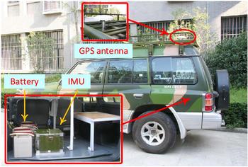
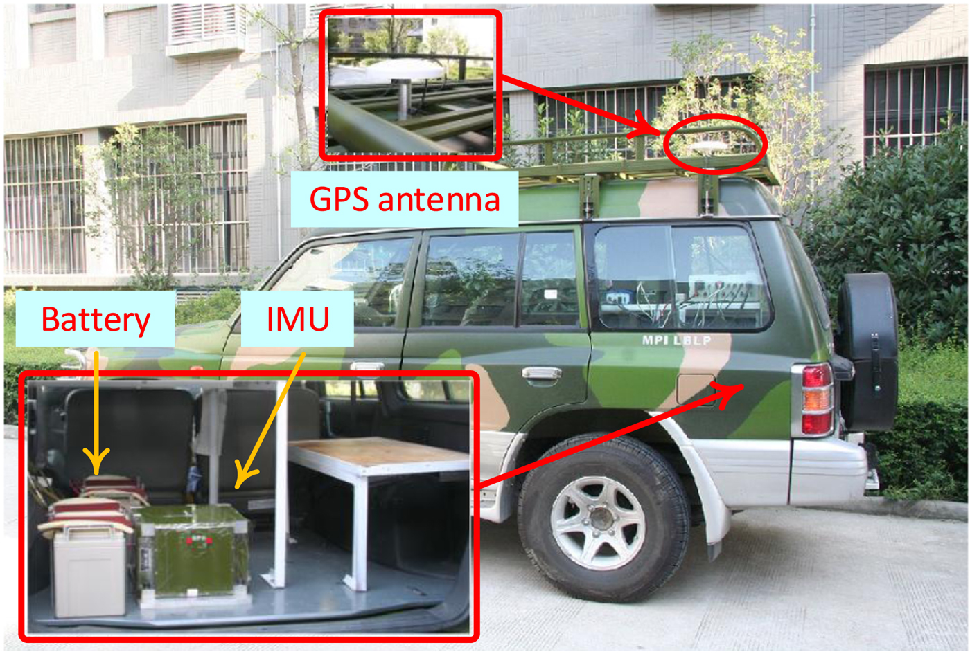
In order to verify the performance of the proposed in-motion alignment method, three land vehicle tests were carried out. The land vehicle was equipped with a single-antenna GPS receiver and a navigation-grade Ring Laser Gyroscope (RLG) IMU with its axes roughly aligning with right, forward, upward directions of the vehicle, as shown in Figure 2.
Experiment vehicle and equipment.
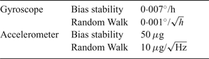
The raw data update rate of the IMU was 200 Hz with its inertial sensors’ specifications listed in Table 1. A Novatel OEM615 GPS receiver with position accuracy of 1·5 m and velocity accuracy of 0·03 m/s was used as the position/velocity reference, while for attitude reference, a stationary-based initial alignment followed by SINS/GPS integrated navigation and Rauch-Tung-Striebel (RTS) post-smoothing (Simon, Reference Simon2006) were conducted as the attitude reference.
Specifications of the inertial sensors.

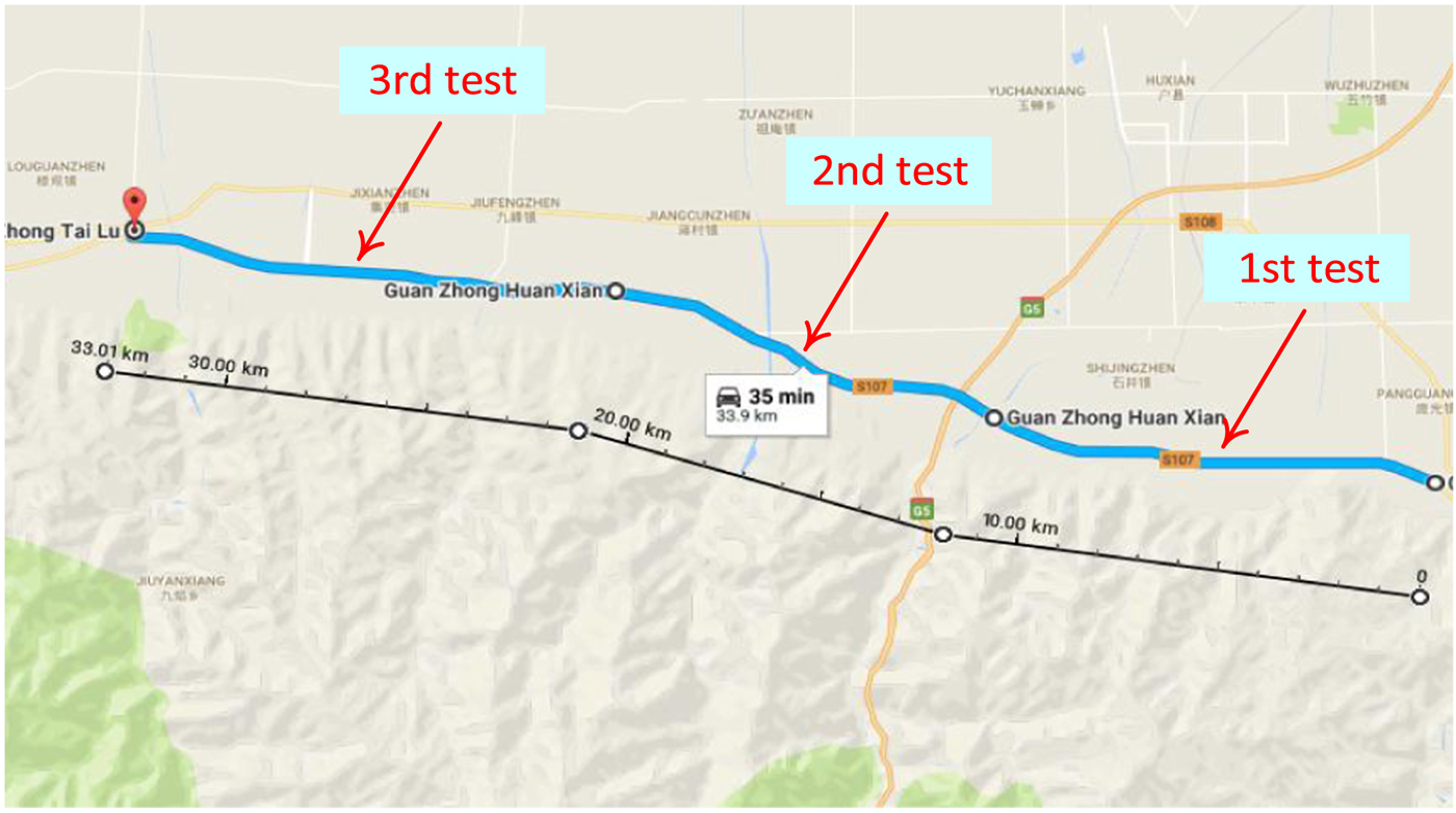
The experimental procedure was designed as follows. Firstly, the car was kept stationary for about 10 minutes and the data was recorded to establish the attitude reference. Then three continuous in-motion alignments were carried out. As shown in Figure 3, we chose an extremely demanding scenario along a country road from east to west with few turns.
Trajectory along the country road during the experiment.
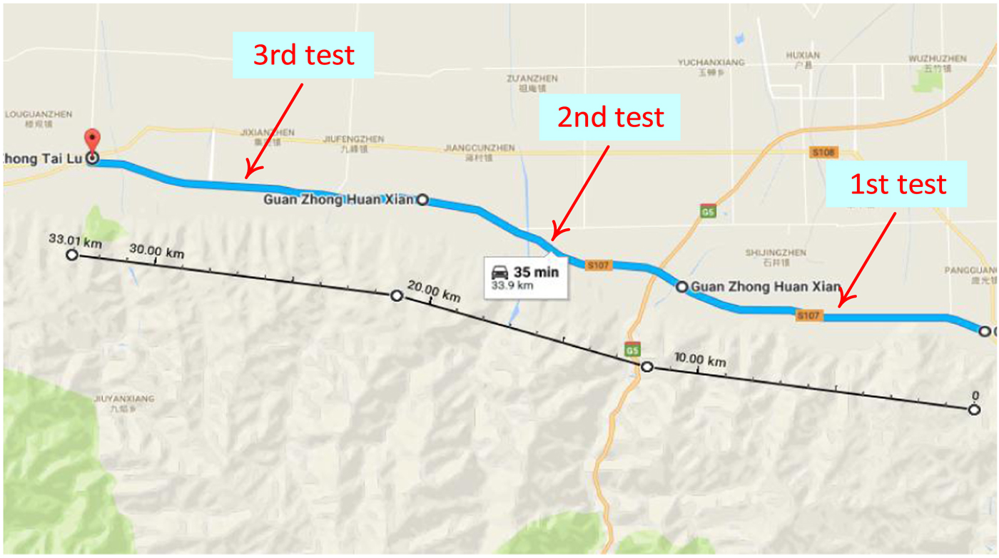
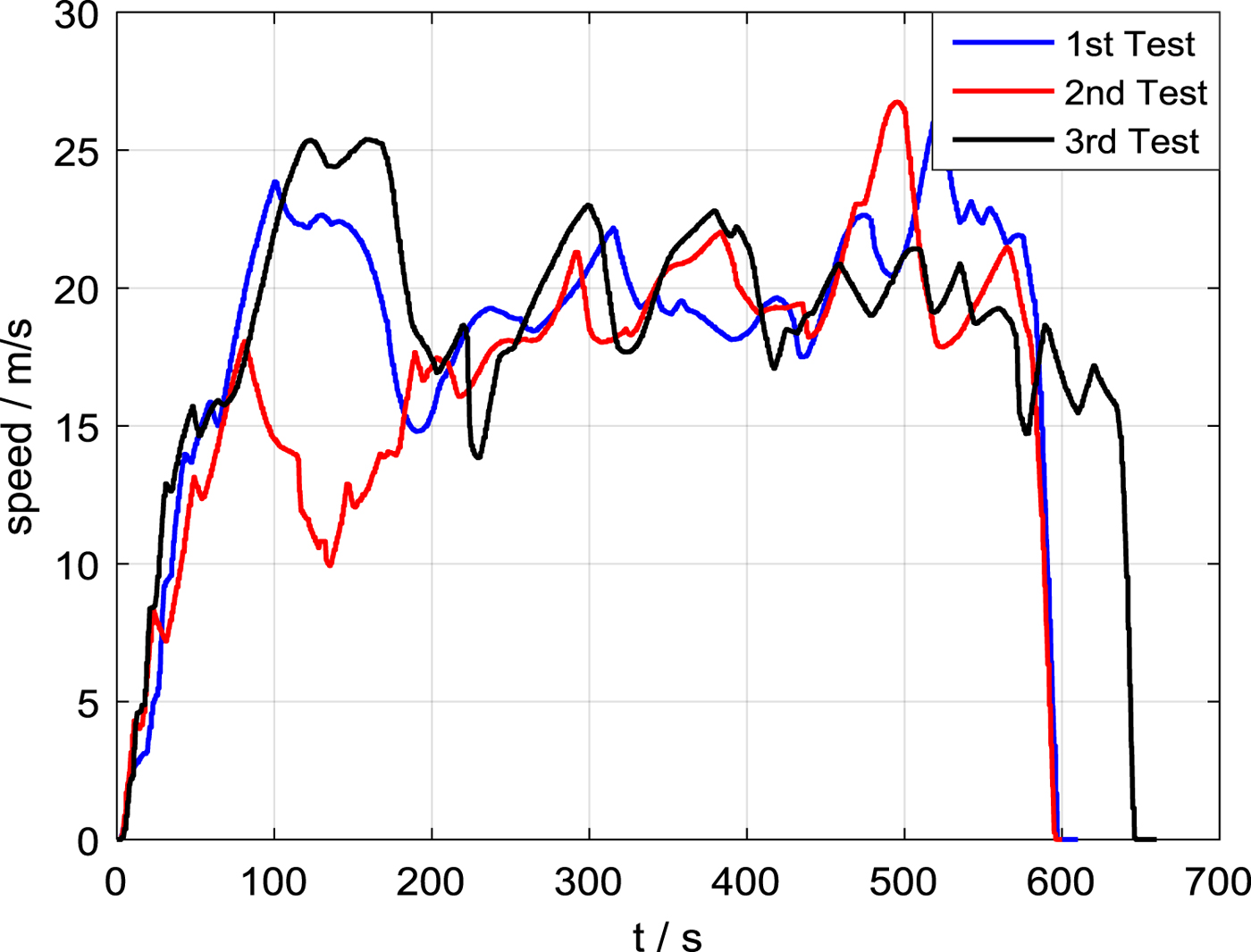
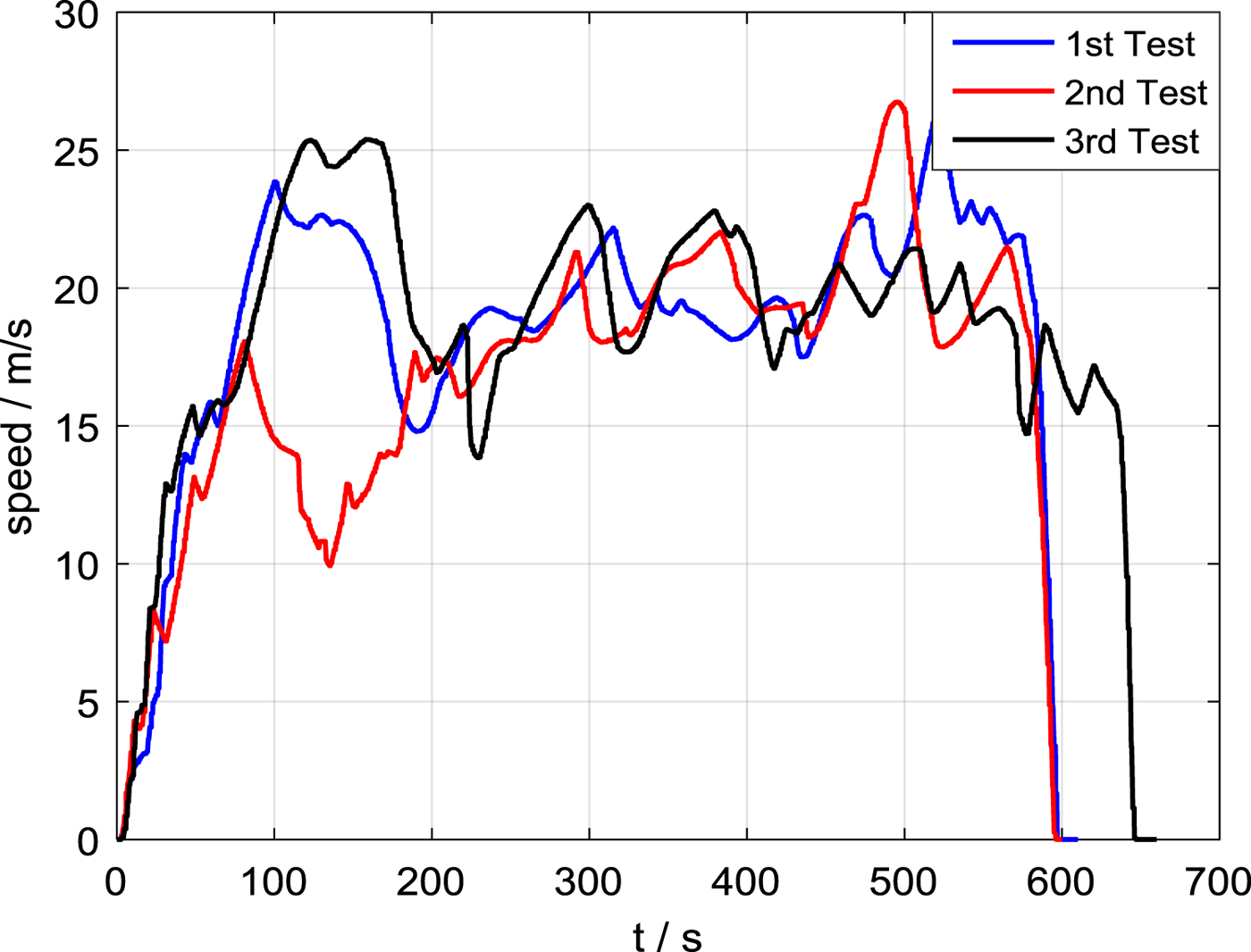
Figure 4 shows the travel speeds during the three tests. It can be seen that the alignment time of each test was about 10 minutes and the vehicle moved immediately when starting a mission. Having no external sensors, the in-motion alignment must start from the zero-speed state to obtain initial velocity information and the initial stationary time can be shortened to less than one second.
Travel speeds during the three vehicular tests.
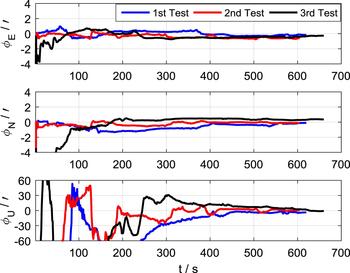
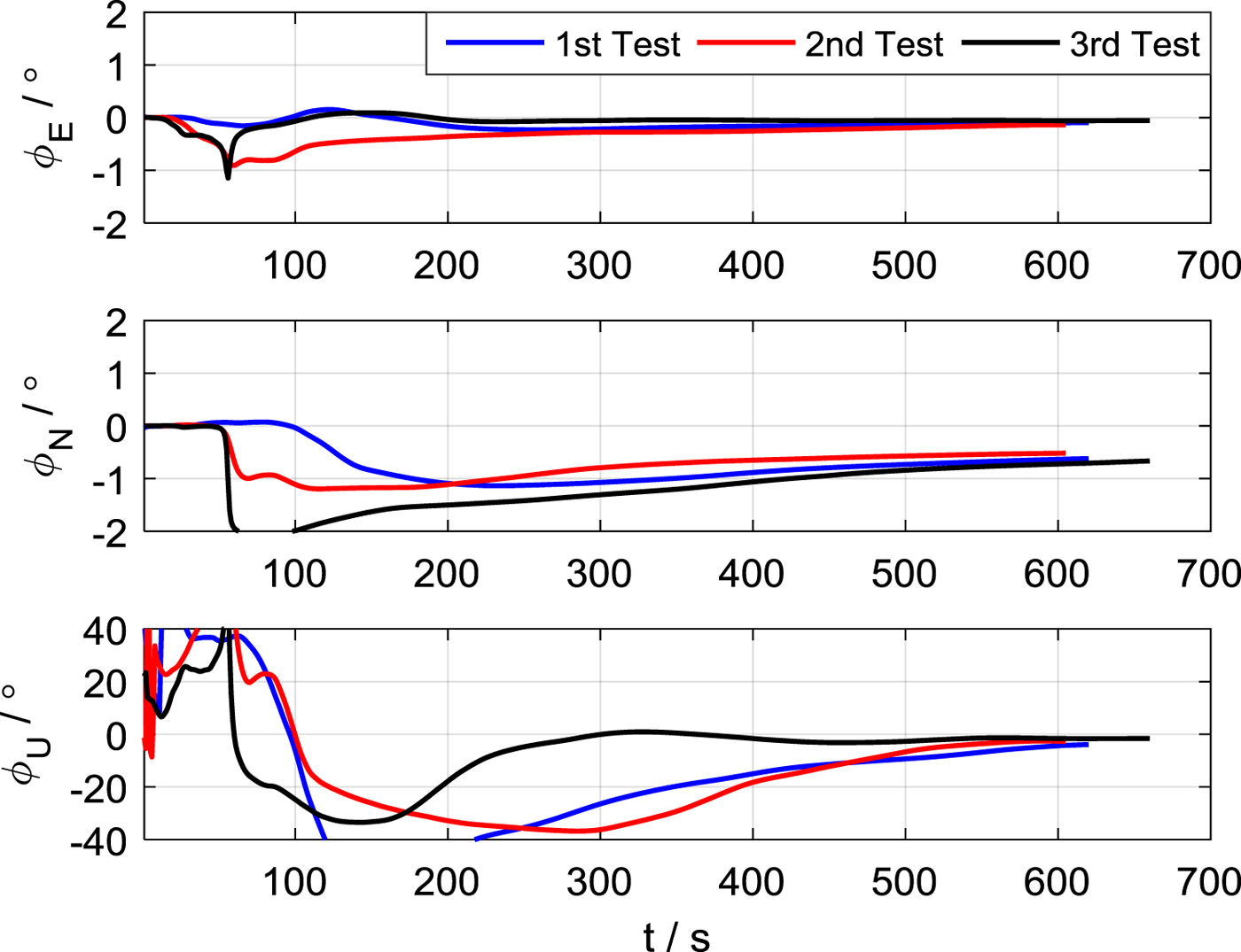
As shown in Figure 5, the attitude errors estimated by DADCA gradually converge with time. At the end of the DADCA process, the level misalignment angles are estimated accurately to within 1° and azimuthal misalignment angle to less than 4°, which meets the requirements of the subsequent linear fine alignment.
Attitude errors of the three DADCA.
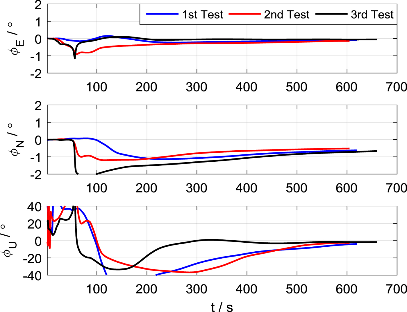
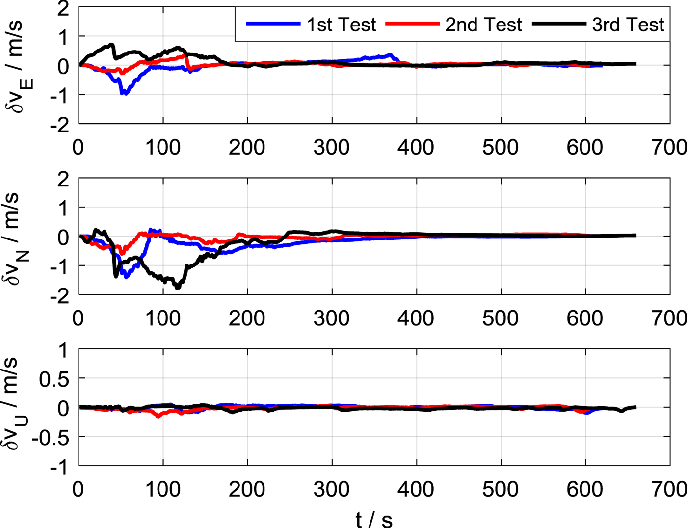
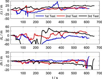
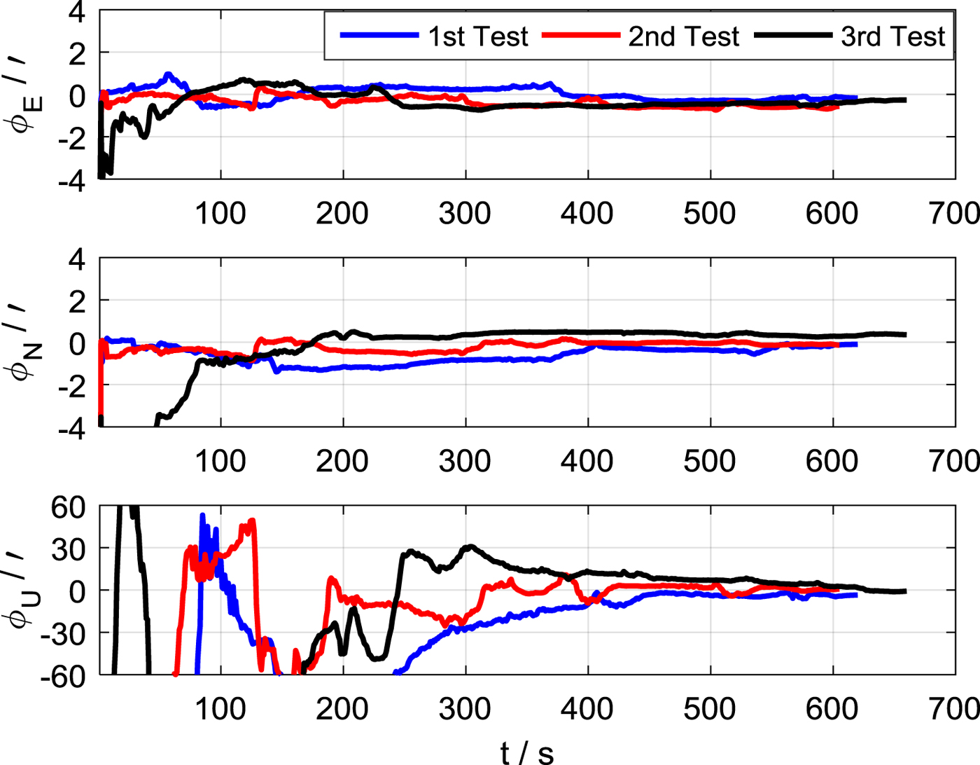
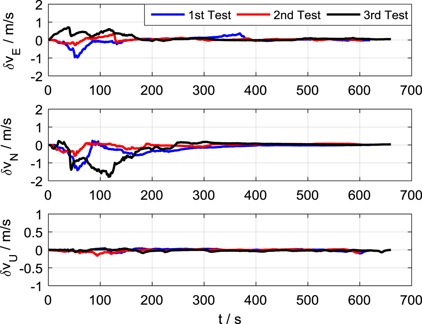
The attitude/velocity/position errors of the BFA processes with SINS/NHC integration are shown in Figures 6–8, respectively. Due to the chosen east-west trajectory, the eastern velocity constraint is lacking most of the time, which leads to a larger eastern velocity error and northern misalignment than the other horizontal direction (northern velocity error and eastern misalignment).
Attitude errors of BFA.
Velocity errors of BFA.
Position errors of BFA.
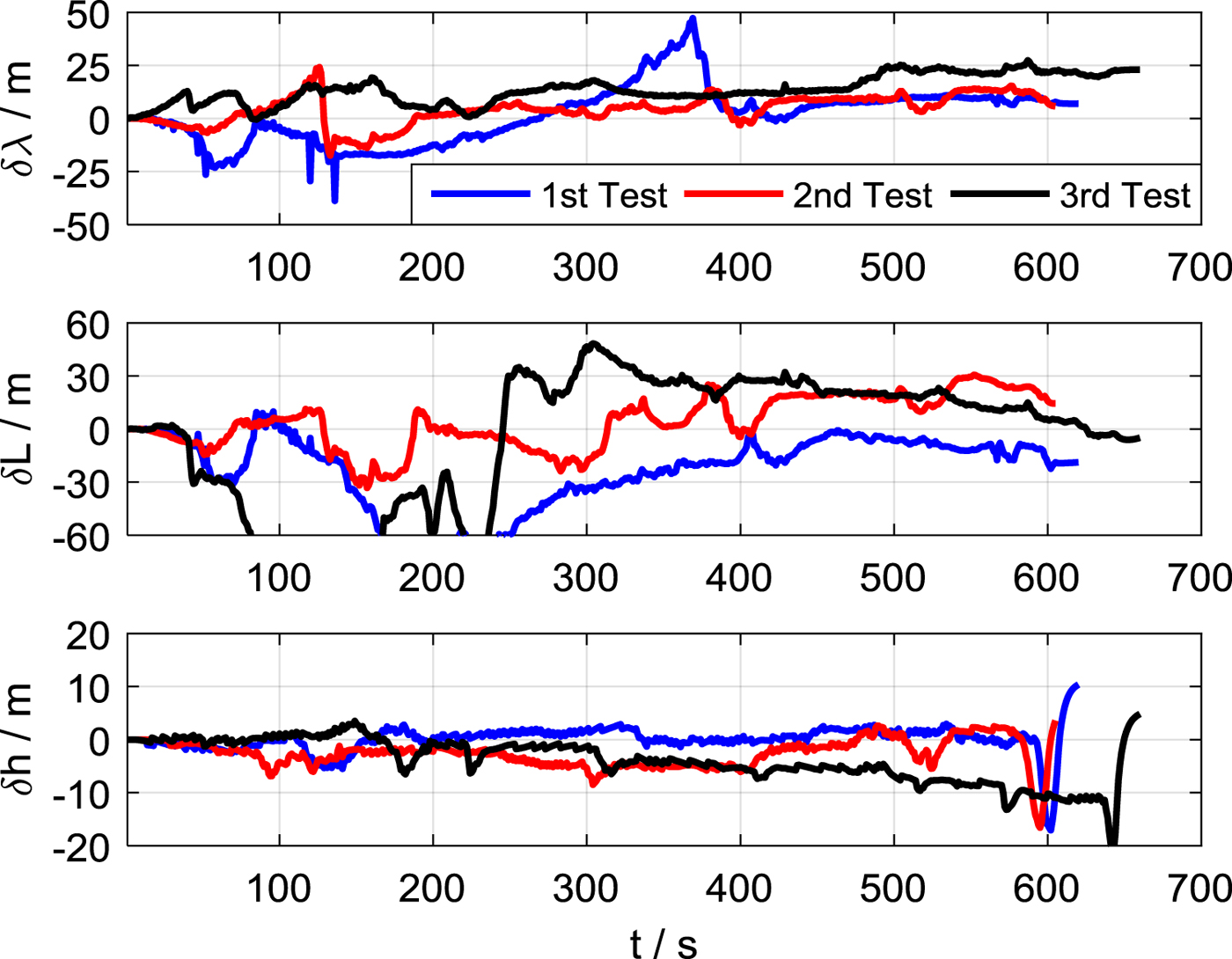
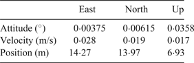
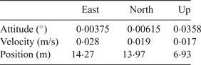
The Root Mean Square (RMS) statistic results at the end of the alignment are listed in Table 2. It can be seen that the azimuth alignment accuracy is 0·0358° (RMS) and the positioning accuracy is about 15 m (RMS). So, even without external auxiliary sensors, the proposed method can align the attitude to high accuracy and continuously determine the velocity and position with satisfactory accuracy.
RMS errors of BFA.
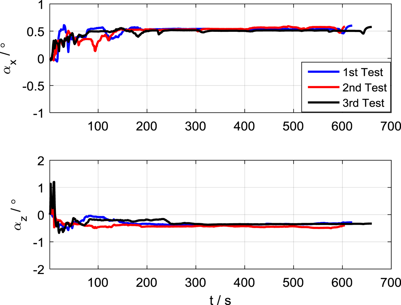
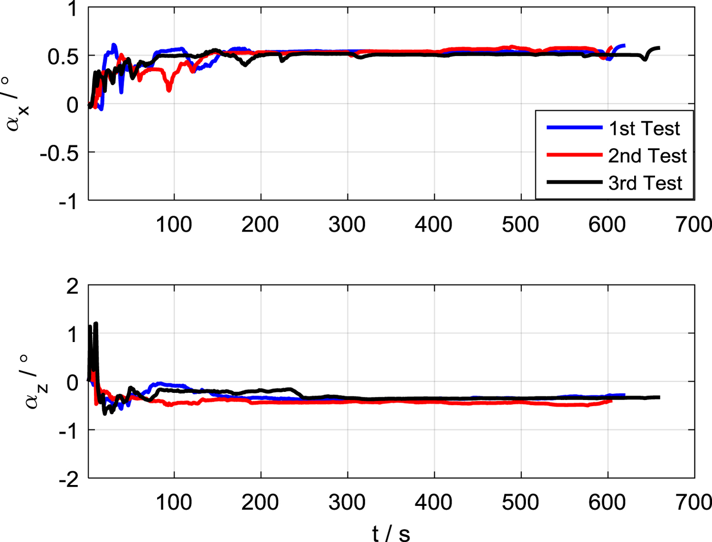
The mounting angles estimated by the BFA process are given in Figure 9. Although the true mounting angles are unknown, the same convergence results in the three tests indicate the reliability of the estimation results. Affected by observability and manoeuvre conditions, the inertial sensor errors cannot be effectively estimated within a limited time apart from the vertical accelerometer bias. This is not a big problem for a navigation-grade SINS with the capability of self-alignment. Given sufficient accuracy of the gyroscopes and accelerometers, satisfactory in-motion alignment accuracy can be obtained by the proposed method.
Mounting angles estimated by BFA.
4. CONCLUSION
The proposed alignment scheme in this paper does not rely on any external sensors to realise accurate in-motion alignment for land vehicle SINS. Once the initial position is available, the vehicle can move immediately, and accurate attitude, position and velocity information can be determined within a given alignment time. Three vehicle tests were carried out along an east-west country road, and the results show that the azimuth alignment accuracy is 0·0358° (RMS) and the positioning errors is about 15 m (RMS). The proposed method here may also be suitable for velocity-aided or position-aided in-motion alignment in other applications such as aviation and marine.