1 Introduction
Magnetic reconnection is a fundamental plasma physics phenomenon, relevant to laboratory, space and astrophysical systems (Biskamp Reference Biskamp2000; Zweibel & Yamada Reference Zweibel and Yamada2009; Uzdensky Reference Uzdensky2011). It involves a rapid topological rearrangement of the magnetic field, leading to efficient magnetic energy conversion and dissipation. Solar flares (Shibata & Magara Reference Shibata and Magara2011) and sawtooth crashes in tokamaks (Hastie Reference Hastie1997) are two popular examples of processes where reconnection plays a key role; others include substorms in the Earth’s magnetosphere (Dungey Reference Dungey1961; Burch et al. Reference Burch, Torbert, Phan, Chen, Moore, Ergun, Eastwood, Gershman, Cassak and Argall2016), particle acceleration in jets and pulsar winds (Cerutti, Uzdensky & Begelman Reference Cerutti, Uzdensky and Begelman2012; Kagan et al. Reference Kagan, Sironi, Cerutti and Giannios2015; Werner et al. Reference Werner, Uzdensky, Cerutti, Nalewajko and Begelman2016), magnetized turbulence (e.g. Matthaeus & Lamkin Reference Matthaeus and Lamkin1986; Servidio et al. Reference Servidio, Matthaeus, Shay, Cassak and Dmitruk2009; Zhdankin et al. Reference Zhdankin, Uzdensky, Perez and Boldyrev2013; Cerri & Califano Reference Cerri and Califano2017; Loureiro & Boldyrev Reference Loureiro and Boldyrev2017; Mallet, Schekochihin & Chandran Reference Mallet, Schekochihin and Chandran2017), etc.
In magnetohydrodynamic (MHD) plasmas, reconnection sites (current sheets) tend to be unstable to the formation of multiple small islands (or plasmoids) provided that the Lundquist number (defined as
 $S=LV_{A}/\unicode[STIX]{x1D702}$
, where
 $L$
is the system size,
 $V_{A}$
the Alfvén speed and
 $\unicode[STIX]{x1D702}$
the magnetic diffusivity) is sufficiently large (typically,
 $S\gtrsim 10^{4}$
). This is known as the plasmoid instability; the current sheets mediated by the plasmoids have an aspect ratio that is much smaller than that of the global sheet, thus triggering fast reconnection (Loureiro, Schekochihin & Cowley Reference Loureiro, Schekochihin and Cowley2007; Lapenta Reference Lapenta2008; Bhattacharjee et al.
Reference Bhattacharjee, Huang, Yang and Rogers2009; Cassak, Shay & Drake Reference Cassak, Shay and Drake2009; Samtaney et al.
Reference Samtaney, Loureiro, Uzdensky, Schekochihin and Cowley2009; Huang & Bhattacharjee Reference Huang and Bhattacharjee2010; Uzdensky, Loureiro & Schekochihin Reference Uzdensky, Loureiro and Schekochihin2010; Loureiro et al.
Reference Loureiro, Samtaney, Schekochihin and Uzdensky2012; Loureiro, Schekochihin & Uzdensky Reference Loureiro, Schekochihin and Uzdensky2013; Loureiro & Uzdensky Reference Loureiro and Uzdensky2016).
In weakly collisional plasmas, where the frozen-flux constraint is broken by kinetic effects instead of collisions, plasmoids are also abundantly observed (e.g. Drake et al. Reference Drake, Swisdak, Che and Shay2006; Ji & Daughton Reference Ji and Daughton2011; Daughton & Roytershteyn Reference Daughton and Roytershteyn2012), suggesting that plasmoid generation and dynamics are robust and fundamental features of reconnecting systems, regardless of the collisionality of the ambient plasma.
Because of its perceived importance – from determining the reconnection rate in MHD plasmas to its possible role in the reconnection onset (Pucci & Velli Reference Pucci and Velli2014; Comisso et al.
Reference Comisso, Lingam, Huang and Bhattacharjee2016; Uzdensky & Loureiro Reference Uzdensky and Loureiro2016; Tolman, Loureiro & Uzdensky Reference Tolman, Loureiro and Uzdensky2018) and in the energy partition (Loureiro et al.
Reference Loureiro, Samtaney, Schekochihin and Uzdensky2012; Numata & Loureiro Reference Numata and Loureiro2015) and particle acceleration and plasma heating (Drake et al.
Reference Drake, Swisdak, Che and Shay2006; Giannios, Uzdensky & Begelman Reference Giannios, Uzdensky and Begelman2009; Oka et al.
Reference Oka, Phan, Krucker, Fujimoto and Shinohara2010; Cerutti et al.
Reference Cerutti, Werner, Uzdensky and Begelman2013; Sironi & Spitkovsky Reference Sironi and Spitkovsky2014; Guo et al.
Reference Guo, Liu, Daughton and Li2015; Zhou et al.
Reference Zhou, Büchner, Bárta, Gan and Liu2015; Sharma, Mitra & Oberoi Reference Sharma, Mitra and Oberoi2017; Werner & Uzdensky Reference Werner and Uzdensky2017) – the plasmoid instability has been the subject of a multitude of theoretical and numerical studies (see Loureiro & Uzdensky (Reference Loureiro and Uzdensky2016) for a brief review). There are also abundant reports of plasmoid observation in solar flares (Milligan et al.
Reference Milligan, McAteer, Dennis and Young2010; Nishizuka et al.
Reference Nishizuka, Takasaki, Asai and Shibata2010; Liu, Chen & Petrosian Reference Liu, Chen and Petrosian2013), coronal jets (Zhang & Ji Reference Zhang and Ji2014) and in the Earth’s magnetotail (Moldwin & Hughes Reference Moldwin and Hughes1992; Zong et al.
Reference Zong, Fritz, Pu, Fu, Baker, Zhang, Lui, Vogiatzis, Glassmeier and Korth2004) and in the magnetospheres of other planets (Jackman, Slavin & Cowley Reference Jackman, Slavin and Cowley2011; Zhang et al.
Reference Zhang, Lu, Baumjohann, Russell, Fedorov, Barabash, Coates, Du, Cao and Nakamura2012; DiBraccio et al.
Reference DiBraccio, Slavin, Imber, Gershman, Raines, Jackman, Boardsen, Anderson, Korth and Zurbuchen2015). This, however, contrasts starkly with plasmoid detection and investigation in laboratory experiments, which have so far been relatively limited, with only a handful of studies reporting plasmoid observation (Fox, Bhattacharjee & Germaschewski Reference Fox, Bhattacharjee and Germaschewski2012; Dorfman et al.
Reference Dorfman, Ji, Yamada, Yoo, Lawrence, Myers and Tharp2013; Jara-Almonte et al.
Reference Jara-Almonte, Ji, Yamada, Yoo and Fox2016; Olson et al.
Reference Olson, Egedal, Greess, Myers, Clark, Endrizzi, Flanagan, Milhone, Peterson and Wallace2016; Hare et al.
Reference Hare, Lebedev, Suttle, Loureiro, Ciardi, Burdiak, Chittenden, Clayson, Eardley and Garcia2017a
,Reference Hare, Suttle, Lebedev, Loureiro, Ciardi, Burdiak, Chittenden, Clayson, Garcia and Niasse
b
, Reference Hare, Suttle, Lebedev, Loureiro, Ciardi, Chittenden, Clayson, Eardley, Garcia and Halliday2018). In all cases, these observations have occurred in non-MHD regions of parameter space (dedicated reconnection experiments have not been able to reach
 $S>10^{4}$
, although future ones might (Forest et al.
Reference Forest, Flanagan, Brookhart and Clark2015; Ji et al.
Reference Ji, Bhattacharjee, Prager, Daughton, Bale, Carter, Crocker, Drake, Egedal and Sarff2015)), and lack a solid theoretical footing.
In a recent paper, Loureiro & Uzdensky (Reference Loureiro and Uzdensky2016) have identified a plasma collisionality regime where the requirement for triggering the plasmoid instability is significantly eased with respect to its pure MHD counterpart. In essence, this regime relies on collisionality being high enough that an MHD current sheet may form in the first place (i.e. the current sheet thickness exceeds any kinetic scale); but small enough that when such a sheet is analysed for its stability to plasmoid formation, two-fluid effects can no longer be neglected. Interestingly, some of the above mentioned experimental reports of plasmoid detection (Dorfman et al. Reference Dorfman, Ji, Yamada, Yoo, Lawrence, Myers and Tharp2013; Jara-Almonte et al. Reference Jara-Almonte, Ji, Yamada, Yoo and Fox2016; Hare et al. Reference Hare, Lebedev, Suttle, Loureiro, Ciardi, Burdiak, Chittenden, Clayson, Eardley and Garcia2017a ,Reference Hare, Suttle, Lebedev, Loureiro, Ciardi, Burdiak, Chittenden, Clayson, Garcia and Niasse b , Reference Hare, Suttle, Lebedev, Loureiro, Ciardi, Chittenden, Clayson, Eardley, Garcia and Halliday2018) seem to sit in, or very close to, this region of parameter space (Hare Reference Hare2017), and it is conceivable that they provide experimental evidence of the existence of this novel regime.
The aim of this paper is to report a set of numerical experiments designed to confirm the existence of the semi-collisional plasmoid instability, with particular focus on experimentally accessible values of the Lundquist number, and precisely map out the regions of parameter space inhabited by it.
2 The semi-collisional plasmoid instability
The linear theory of the plasmoid instability in MHD plasmas (Loureiro et al.
Reference Loureiro, Schekochihin and Cowley2007; Bhattacharjee et al.
Reference Bhattacharjee, Huang, Yang and Rogers2009; Loureiro et al.
Reference Loureiro, Schekochihin and Uzdensky2013) assumes the existence of a Sweet–Parker (SP) current sheet (Parker Reference Parker1957; Sweet Reference Sweet and Lehnert1958), which is taken as the background equilibrium whose stability is analysed. In standard tearing mode fashion (Furth, Killeen & Rosenbluth Reference Furth, Killeen and Rosenbluth1963), the calculation divides the spatial domain into an outer region, where resistivity effects can be ignored, and an inner region – a boundary layer of thickness
 $\unicode[STIX]{x1D6FF}_{\text{in}}$
– where resistivity matters.
Let us revisit this question adding minimal kinetic two-fluid effects: we wish to consider the case where the ion sound Larmor radius,
 $\unicode[STIX]{x1D70C}_{s}$
, although smaller than the thickness of the SP current sheet,
 $\unicode[STIX]{x1D6FF}_{\text{SP}}$
, is however larger than the boundary layer of the MHD linear plasmoid instability:
 $\unicode[STIX]{x1D6FF}_{\text{SP}}\gg \unicode[STIX]{x1D70C}_{s}\gg \unicode[STIX]{x1D6FF}_{\text{in}}$
.Footnote
1
This obviously implies that MHD is no longer a sufficient description. On the other hand, collisionality (
 $\unicode[STIX]{x1D708}_{\text{ei}}$
) will still be taken to be large enough that the frozen-flux constraint is broken by resistivity, instead of electron inertia; i.e.
 $\unicode[STIX]{x1D6FF}_{\text{in}}\gg d_{e}$
, with
 $d_{e}$
the electron skin depth (which results from the ordering
 $\unicode[STIX]{x1D708}_{\text{ei}}\gg \unicode[STIX]{x1D6FE}$
, where
 $\unicode[STIX]{x1D6FE}$
is the tearing mode growth rate). Nonetheless, the semi-collisional tearing mode requires
 $\unicode[STIX]{x1D6FF}_{\text{in}}\ll \unicode[STIX]{x1D70C}_{s}$
and transitions to the usual collisional (MHD) tearing mode in the limit
 $\unicode[STIX]{x1D6FF}_{\text{in}}\gg \unicode[STIX]{x1D70C}_{s}$
, and becomes the collisionless tearing mode when the collision frequency is decreased such that
 $\unicode[STIX]{x1D708}_{\text{ei}}\ll \unicode[STIX]{x1D6FE}$
(Drake & Lee Reference Drake and Lee1977). On a qualitative level, this regime does not require ion finite Larmor orbit effects (i.e. it exists in the limit
 $\unicode[STIX]{x1D70C}_{i}\rightarrow 0$
as long as
 $\unicode[STIX]{x1D70C}_{s}$
remains finite). But our arguments below assume
 $\unicode[STIX]{x1D70C}_{i}\sim \unicode[STIX]{x1D70C}_{s}$
, and our simulations will consider the case when
 $T_{0i}=T_{0e}$
.
The expressions for the growth rate of the plasmoid instability in this regime can be obtained from the appropriate tearing mode theory (Drake & Lee Reference Drake and Lee1977; Pegoraro & Schep Reference Pegoraro and Schep1986; Zocco & Schekochihin Reference Zocco and Schekochihin2011), following the usual procedure of replacing the equilibrium scale length with
 $\unicode[STIX]{x1D6FF}_{\text{SP}}\sim LS^{-1/2}$
, where
 $L$
is the length of the current sheet (Tajima & Shibata Reference Tajima and Shibata2002; Bhattacharjee et al.
Reference Bhattacharjee, Huang, Yang and Rogers2009).
For small values of the tearing mode instability parameter
 $\unicode[STIX]{x1D6E5}^{\prime }$
, i.e.
 $\unicode[STIX]{x1D6E5}^{\prime }\unicode[STIX]{x1D6FF}_{\text{in}}\ll 1$
, we find
 $$\begin{eqnarray}\displaystyle & \unicode[STIX]{x1D6FE}L/V_{A}\sim (kL)^{2/3}(\unicode[STIX]{x1D6E5}^{\prime }\unicode[STIX]{x1D70C}_{s})^{2/3}, & \displaystyle\end{eqnarray}$$
 $$\begin{eqnarray}\displaystyle & \unicode[STIX]{x1D6FF}_{\text{in}}/L\sim (\unicode[STIX]{x1D6E5}^{\prime }\unicode[STIX]{x1D70C}_{s})^{1/6}(kL)^{-1/3}S^{-1/2}, & \displaystyle\end{eqnarray}$$
where
 $\unicode[STIX]{x1D6FE}$
is the growth rate of a mode with wavenumber
 $k$
. This expression can be simplified if
 $\unicode[STIX]{x1D6E5}^{\prime }$
is not too small, such that it can be approximated as
 $\unicode[STIX]{x1D6E5}^{\prime }\unicode[STIX]{x1D6FF}_{\text{SP}}\sim 1/(k\unicode[STIX]{x1D6FF}_{\text{SP}})$
, as pertains to the usual Harris-like magnetic configuration (Harris Reference Harris1962). In that case, we obtain
 $$\begin{eqnarray}\unicode[STIX]{x1D6FE}L/V_{A}\sim (\unicode[STIX]{x1D70C}_{s}/L)^{2/3}S^{2/3},\end{eqnarray}$$
and the validity condition
 $\unicode[STIX]{x1D6E5}^{\prime }\unicode[STIX]{x1D6FF}_{\text{in}}\ll 1$
becomes
 $kL\gg (\unicode[STIX]{x1D70C}_{s}/L)^{1/9}S^{4/9}$
. Note that this expression is independent of
 $k$
to lowest order.
In the opposite limit of large
 $\unicode[STIX]{x1D6E5}^{\prime }$
, i.e.
 $\unicode[STIX]{x1D6E5}^{\prime }\unicode[STIX]{x1D6FF}_{\text{in}}\gg 1$
, we instead have
 $$\begin{eqnarray}\displaystyle & \unicode[STIX]{x1D6FE}L/V_{A}\sim (\unicode[STIX]{x1D70C}_{s}/L)^{4/7}S^{2/7}(kL)^{6/7}, & \displaystyle\end{eqnarray}$$
 $$\begin{eqnarray}\displaystyle & \unicode[STIX]{x1D6FF}_{\text{in}}/L\sim (\unicode[STIX]{x1D70C}_{s}/L)^{1/7}(kL)^{-2/7}S^{-3/7}. & \displaystyle\end{eqnarray}$$
The fastest growing mode is yielded by the intersection of these two branches (Loureiro & Uzdensky Reference Loureiro and Uzdensky2016)Footnote 2
 $$\begin{eqnarray}\displaystyle & \unicode[STIX]{x1D6FE}_{\text{max}}L/V_{A}\sim (\unicode[STIX]{x1D70C}_{s}/L)^{2/3}S^{2/3}, & \displaystyle\end{eqnarray}$$
 $$\begin{eqnarray}\displaystyle & k_{\text{max}}L\sim (\unicode[STIX]{x1D70C}_{s}/L)^{1/9}S^{4/9}, & \displaystyle\end{eqnarray}$$
 $$\begin{eqnarray}\displaystyle & \unicode[STIX]{x1D6FF}_{\text{in}}/L\sim (\unicode[STIX]{x1D70C}_{s}/L)^{1/9}S^{-5/9}. & \displaystyle\end{eqnarray}$$
The validity of these expressions rests on two conditions:
 $\unicode[STIX]{x1D6FF}_{\text{SP}}\gg \unicode[STIX]{x1D70C}_{s}$
, and
 $\unicode[STIX]{x1D70C}_{s}\gg \unicode[STIX]{x1D6FF}_{\text{in}}$
. Using (2.8), these therefore imply that the semi-collisional plasmoid instability inhabits the region of parameter space defined byFootnote
3
 $$\begin{eqnarray}(L/\unicode[STIX]{x1D70C}_{s})^{2}\gg S\gg (L/\unicode[STIX]{x1D70C}_{s})^{8/5}.\end{eqnarray}$$
An alternative current sheet profile worth considering – and the one we will make use of in this paper – is that of a sinusoidal-like magnetic field,
 $B_{y}(x)=B_{0}\sin (x/a)$
, for which
 $\unicode[STIX]{x1D6E5}^{\prime }\unicode[STIX]{x1D6FF}_{\text{SP}}\sim 1/(k\unicode[STIX]{x1D6FF}_{\text{SP}})^{2}$
. For small
 $\unicode[STIX]{x1D6E5}^{\prime }$
, we obtain,
 $$\begin{eqnarray}\displaystyle & \unicode[STIX]{x1D6FE}L/V_{A}\sim (\unicode[STIX]{x1D70C}_{s}/L)^{2/3}(kL)^{-2/3}S, & \displaystyle\end{eqnarray}$$
 $$\begin{eqnarray}\displaystyle & \unicode[STIX]{x1D6FF}_{\text{in}}\sim (\unicode[STIX]{x1D70C}_{s}/L)^{1/6}(kL)^{-2/3}S^{-1/4}, & \displaystyle\end{eqnarray}$$
valid if
 $kL\gg (\unicode[STIX]{x1D70C}_{s}/L)^{1/16}S^{15/32}$
. For large
 $\unicode[STIX]{x1D6E5}^{\prime }$
, the scaling for
 $\unicode[STIX]{x1D6FE}L/V_{A}$
is same as in (2.4), as there is no explicit dependence on
 $\unicode[STIX]{x1D6E5}^{\prime }$
. The fastest growing mode is therefore characterized by
 $$\begin{eqnarray}\displaystyle & \unicode[STIX]{x1D6FE}_{\text{max}}L/V_{A}\sim (\unicode[STIX]{x1D70C}_{s}/L)^{5/8}S^{11/16}, & \displaystyle\end{eqnarray}$$
 $$\begin{eqnarray}\displaystyle & k_{\text{max}}L\sim (\unicode[STIX]{x1D70C}_{s}/L)^{1/16}S^{15/32}, & \displaystyle\end{eqnarray}$$
 $$\begin{eqnarray}\displaystyle & \unicode[STIX]{x1D6FF}_{\text{in}}/L\sim (\unicode[STIX]{x1D70C}_{s}/L)^{1/8}S^{-9/16}. & \displaystyle\end{eqnarray}$$
Figure 1 illustrates both limits of the dispersion relation, and their intersection, for two different combinations of the two relevant parameters,
 $S$
and
 $L/\unicode[STIX]{x1D70C}_{s}$
. In the Appendix we recover these scalings via direct numerical simulation, confirming both their validity and the ability of the code Viriato (Loureiro et al.
Reference Loureiro, Dorland, Fazendeiro, Kanekar, Mallet, Vilelas and Zocco2016), which we will employ in this paper (see §§ 3 and 4), to recover them.
Dispersion relation for the semi-collisional plasmoid instability for two different combinations of the relevant parameters:
 $(S,L/\unicode[STIX]{x1D70C}_{s})=(1000,35)$
(red lines) and
 $(S,L/\unicode[STIX]{x1D70C}_{s})=(10^{6},4000)$
(blue lines). Solid lines represent the case of
 $\unicode[STIX]{x1D6E5}^{\prime }\unicode[STIX]{x1D6FF}_{\text{in}}\ll 1$
(2.11), whereas dashed lines are for the case of
 $\unicode[STIX]{x1D6E5}^{\prime }\unicode[STIX]{x1D6FF}_{\text{in}}\gg 1$
(2.4). Respectively, these lines are only valid to the right, or to the left, of their intersection. Their point of intersection provides an estimate of the most unstable wavenumber and corresponding growth rate.

In this case of a sinusoidal-like current sheet profile, equation (2.9) is replaced by:
 $$\begin{eqnarray}(L/\unicode[STIX]{x1D70C}_{s})^{2}\gg S\gg (L/\unicode[STIX]{x1D70C}_{s})^{14/9}.\end{eqnarray}$$
The lower bound here has only a slightly smaller exponent than (and is in practice difficult to discern from) the Harris-like case of (2.9).
Equations (2.9) and (2.15) lead to the interesting suggestion that this particular version of the plasmoid instability can be obtained at relatively low values of
 $S$
, provided that the system (the current sheet length
 $L$
, to be precise) is not too large compared with
 $\unicode[STIX]{x1D70C}_{s}$
. In other words, the lower bound of
 $S\sim 10^{4}$
that pertains to the MHD version of the plasmoid instability (Biskamp Reference Biskamp1986; Loureiro et al.
Reference Loureiro, Cowley, Dorland, Haines and Schekochihin2005; Samtaney et al.
Reference Samtaney, Loureiro, Uzdensky, Schekochihin and Cowley2009; Baty Reference Baty2014) is replaced by a function in the semi-collisional regime,
 $(L/\unicode[STIX]{x1D70C}_{s})^{14/9}$
, or
 $(L/\unicode[STIX]{x1D70C}_{s})^{8/5}$
, as appropriate. This growth of plasmoids at low
 $S$
is possible in the semi-collisional regime due to the presence of the
 $\unicode[STIX]{x1D70C}_{s}$
scale, which is unavailable in MHD. The tearing calculation in this regime has to account for nested boundary layers instead of a single one: this introduces an extra parameter in the problem and makes the critical Lundquist number (derived from the requirement that the condition for semi-collisional regime,
 $\unicode[STIX]{x1D6FF}_{\text{SP}}>\unicode[STIX]{x1D70C}_{s}>\unicode[STIX]{x1D6FF}_{\text{in}}$
be satisfied) become dependent on this new parameter.
From both the experimental and the numerical points of view, this feature of low critical Lundquist number is a significant advantage. In particular, this regime should be available to reconnection experiments such as the magnetic reconnection experiment (MRX) (Yamada et al.
Reference Yamada, Ji, Hsu, Carter, Kulsrud, Bretz, Jobes, Ono and Perkins1997), terrestrial reconnection experiment (TREX) (Olson et al.
Reference Olson, Egedal, Greess, Myers, Clark, Endrizzi, Flanagan, Milhone, Peterson and Wallace2016), facility for laboratory reconnection experiments (FLARE) (Ji & Daughton Reference Ji and Daughton2011) and the mega ampere generator for plasma implosion experiments (Magpie) (Hare et al.
Reference Hare, Lebedev, Suttle, Loureiro, Ciardi, Burdiak, Chittenden, Clayson, Eardley and Garcia2017a
,Reference Hare, Suttle, Lebedev, Loureiro, Ciardi, Burdiak, Chittenden, Clayson, Garcia and Niasse
b
, Reference Hare, Suttle, Lebedev, Loureiro, Ciardi, Chittenden, Clayson, Eardley, Garcia and Halliday2018). Indeed, as we mention above, it is tempting to attribute recent reports of experimental plasmoid observation (Dorfman et al.
Reference Dorfman, Ji, Yamada, Yoo, Lawrence, Myers and Tharp2013; Jara-Almonte et al.
Reference Jara-Almonte, Ji, Yamada, Yoo and Fox2016; Hare et al.
Reference Hare, Lebedev, Suttle, Loureiro, Ciardi, Burdiak, Chittenden, Clayson, Eardley and Garcia2017a
,Reference Hare, Suttle, Lebedev, Loureiro, Ciardi, Burdiak, Chittenden, Clayson, Garcia and Niasse
b
, Reference Hare, Suttle, Lebedev, Loureiro, Ciardi, Chittenden, Clayson, Eardley, Garcia and Halliday2018) to this version of the plasmoid instability – or to its
 $\unicode[STIX]{x1D6FD}\sim 1$
analogue (Baalrud et al.
Reference Baalrud, Bhattacharjee, Huang and Germaschewski2011) (
 $\unicode[STIX]{x1D6FD}$
is the ratio of the plasma pressure to the magnetic pressure). In the weak guide field or
 $\unicode[STIX]{x1D6FD}\sim 1$
case, the relevant scale is the ion-inertial scale
 $d_{i}$
(instead of
 $\unicode[STIX]{x1D70C}_{s}$
), and the same feature of scale-dependent critical Lundquist number is expected to hold.
Despite these speculations and conjectures, the existence of this regime of the plasmoid instability has not been confirmed via direct numerical simulations, and indeed there are a couple of issues that may raise suspicion. In particular, we note that all of the scalings above are predicated on there being an asymptotic separation between the scales involved, namely
 $\unicode[STIX]{x1D6FF}_{\text{SP}}\gg \unicode[STIX]{x1D70C}_{s}\gg \unicode[STIX]{x1D6FF}_{\text{in}}$
.Footnote
4
As the Lundquist number is made smaller, this scale separation is inevitably lost, and thus the claim that the semi-collisional plasmoid instability may be obtainable at the relatively low values of
 $S$
and
 $L/\unicode[STIX]{x1D70C}_{s}$
that are within the reach of existing experiments needs careful numerical validation.
An additional concern of significant relevance is that of whether the Sweet–Parker sheet that is assumed as the background for the instability derived here is realizable. As has been pointed out (Loureiro et al.
Reference Loureiro, Schekochihin and Cowley2007; Pucci & Velli Reference Pucci and Velli2014; Uzdensky & Loureiro Reference Uzdensky and Loureiro2016), the existence of a super-Alfvénic instability whose growth rate diverges as
 $S\rightarrow \infty$
indicates that the equilibrium that it arises from, may never form in the first place. We think this claim is pertinent at high values of the Lundquist number. However, in the opposite limit of relatively low
 $S$
with which we are mostly concerned here, where the instability is only mildly super-Alfvénic, a Sweet–Parker sheet may still form and beget the instability.
This paper aims to answer these questions by means of direct numerical simulations of a reconnecting system where the current sheet is not prescribed, but rather allowed to form self-consistently.
3 The model
The weak collisionality of a large number of reconnecting environments demands the use of a kinetic description. In the most general case, one is forced to adopt a first-principles formalism (such as particle-in-cell, or the six-dimensional (6-D) Vlasov (or Boltzmann) equation), with its inherent analytical and numerical complexity. In many situations, however, a strong component of the magnetic field is present that is perpendicular to the reconnection plane. This guide field offers an opportunity for significant simplification: the 5-D gyrokinetic formalism (Frieman & Chen Reference Frieman and Chen1982; Howes et al. Reference Howes, Cowley, Dorland, Hammett, Quataert and Schekochihin2006).
Further simplification is possible if, in addition, one considers plasmas such that the electron
 $\unicode[STIX]{x1D6FD}$
is sufficiently low to be comparable to the electron-to-ion mass ratio (
 $m_{e}/m_{i}$
); a case in point is the solar corona, as mentioned earlier in § 2. Leveraging on these assumptions (strong guide field and low
 $\unicode[STIX]{x1D6FD}$
), a reduced-gyrokinetic formalism was recently derived (dubbed the ‘kinetic reduced electron heating model’, or KREHM) (Zocco & Schekochihin Reference Zocco and Schekochihin2011). One of its appealing features is that the phase space is reduced further to four dimensions (position vector and velocity in the guide-field direction only), thus rendering computations, and even analytic theory, significantly more manageable than fully kinetic approaches.
In this work, we use the KREHM equations to investigate the plasmoid instability in the semi-collisional regime. We will restrict our numerical investigations to the two spatial dimensions comprising the reconnection plane,
 $(x,y)$
. With this restriction, the KREHM equations become:
 $$\begin{eqnarray}\displaystyle & \!\displaystyle \frac{1}{n_{0e}}\frac{\text{d}\unicode[STIX]{x1D6FF}n_{e}}{\text{d}t}=\frac{1}{B_{0}}\left\{A_{\Vert },\frac{e}{cm_{e}}d_{e}^{2}\unicode[STIX]{x1D6FB}_{\bot }^{2}A_{\Vert }\right\}\!,\qquad & \displaystyle\end{eqnarray}$$
 $$\begin{eqnarray}\displaystyle & \!\displaystyle \frac{\text{d}}{\text{d}t}(A_{\Vert }-d_{e}^{2}\unicode[STIX]{x1D6FB}_{\bot }^{2}A_{\Vert })=\unicode[STIX]{x1D702}\unicode[STIX]{x1D6FB}_{\bot }^{2}A_{\Vert }-\frac{cT_{0e}}{eB_{0}}\left\{A_{\Vert },\left(\frac{\unicode[STIX]{x1D6FF}n_{e}}{n_{0e}}+\frac{\unicode[STIX]{x1D6FF}T_{\Vert e}}{T_{0e}}\right)\!\right\}\!,\qquad & \displaystyle\end{eqnarray}$$
 $$\begin{eqnarray}\displaystyle & \!\displaystyle \frac{\text{d}g_{e}}{\text{d}t}-\frac{v_{\Vert }}{B_{0}}\left\{A_{\Vert },\left(\!g_{e}-\frac{\unicode[STIX]{x1D6FF}T_{\Vert e}}{T_{0e}}F_{0e}\right)\!\right\}=C[g_{e}]-\left(\!1-\frac{2v_{\Vert }^{2}}{v_{\text{the}}^{2}}\right)\frac{F_{0e}}{B_{0}}\left\{A_{\Vert },\frac{e}{cm_{e}}d_{e}^{2}\unicode[STIX]{x1D6FB}_{\bot }^{2}A_{\Vert }\right\}\!,\qquad & \displaystyle\end{eqnarray}$$
where
 $$\begin{eqnarray}\frac{\text{d}}{\text{d}t}=\frac{\unicode[STIX]{x2202}}{\unicode[STIX]{x2202}t}+\frac{c}{B_{0}}\{\unicode[STIX]{x1D719},\ldots \}.\end{eqnarray}$$
Here,
 $\unicode[STIX]{x1D719}$
is electrostatic potential and
 $\{\ldots \}$
denotes the Poisson bracket, defined for any two fields
 $P$
,
 $Q$
as
 $\{P,Q\}=\unicode[STIX]{x2202}_{x}P\unicode[STIX]{x2202}_{y}Q-\unicode[STIX]{x2202}_{y}P\unicode[STIX]{x2202}_{x}Q$
.
Equations (3.1) and (3.2) evolve the zeroth and first moments of the perturbed electron distribution function,
 $\unicode[STIX]{x1D6FF}f_{e}$
. The zeroth moment is the electron density perturbation,
 $\unicode[STIX]{x1D6FF}n_{e}$
. The first moment is the parallel electron flow,
 $u_{\Vert e}$
, and is related to the parallel component of the magnetic vector potential
 $A_{\Vert }$
by
 $u_{\Vert e}=(e/cm_{e})d_{e}^{2}\unicode[STIX]{x1D6FB}_{\bot }^{2}A_{\Vert }$
. The perturbed electron distribution function is given by
 $$\begin{eqnarray}\unicode[STIX]{x1D6FF}f_{e}=g_{e}+(\unicode[STIX]{x1D6FF}n_{e}/n_{0e}+2v_{\Vert }u_{\Vert e}/v_{\text{the}}^{2})F_{0e},\end{eqnarray}$$
where
 $F_{0e}=n_{0e}/(\unicode[STIX]{x03C0}/v_{\text{the}}^{2})^{3/2}\exp [-(v_{\Vert }^{2}+v_{\bot }^{2})/v_{\text{the}}^{2}]$
is the Maxwellian equilibrium, and
 $v_{\Vert }$
and
 $v_{\bot }$
are, respectively, the velocity coordinates parallel and perpendicular to the guide-field direction. The electron thermal speed is
 $v_{\text{the}}=\sqrt{2T_{0e}/m_{e}}$
, with
 $e$
the electron charge, and
 $m_{e}$
its mass. Note that this is a
 $\unicode[STIX]{x1D6FF}f$
formulation, so any fluctuating quantity is necessarily much smaller than the equilibrium quantity.
The quantity
 $g_{e}$
is dubbed the reduced electron distribution function; its evolution is given by (3.3). It contains all the moments of
 $\unicode[STIX]{x1D6FF}f_{e}$
higher than
 $\unicode[STIX]{x1D6FF}n_{e}$
and
 $u_{\Vert e}$
. For example, parallel temperature fluctuations (second-order moment) are given by
 $\unicode[STIX]{x1D6FF}T_{\Vert e}/T_{0e}=(1/n_{0e})\int \,\text{d}^{3}\boldsymbol{v}(2v_{\Vert }^{2}/v_{\text{the}}^{2})g_{e}$
. On the right-hand side,
 $C[g_{e}]$
denotes the collision operator, and the second term represents what survives of the so-called ‘gyrokinetic potential’ in this expansion.
The background magnetic guide field is
 $B_{0}$
; and
 $n_{0e}$
,
 $T_{0e}$
are the background electron density and temperature, respectively. Other symbols introduced above are the electron skin depth,
 $d_{e}=c/\unicode[STIX]{x1D714}_{\text{pe}}$
, with
 $\unicode[STIX]{x1D714}_{\text{pe}}=\sqrt{4\unicode[STIX]{x03C0}n_{0e}\text{e}^{2}/m_{e}}$
the electron plasma frequency.
The perturbed electron density,
 $\unicode[STIX]{x1D6FF}n_{e}$
, and the electrostatic potential are related via the gyrokinetic Poisson law,
 $$\begin{eqnarray}\frac{\unicode[STIX]{x1D6FF}n_{e}}{n_{0e}}=\frac{1}{\unicode[STIX]{x1D70F}}(\hat{\unicode[STIX]{x1D6E4}}_{0}-1)\frac{\text{e}\unicode[STIX]{x1D719}}{T_{0e}},\end{eqnarray}$$
where,
 $\unicode[STIX]{x1D70F}=T_{0i}/T_{0e}$
is the ion to electron background temperature ratio, and
 $\hat{\unicode[STIX]{x1D6E4}}_{0}$
is a real space operator whose Fourier transform is
 $\unicode[STIX]{x1D6E4}_{0}(\unicode[STIX]{x1D6FC})=I_{0}(\unicode[STIX]{x1D6FC})\text{e}^{-\unicode[STIX]{x1D6FC}}$
, with
 $I_{0}$
the modified Bessel function of zeroth order and
 $\unicode[STIX]{x1D6FC}=k_{\bot }^{2}{\unicode[STIX]{x1D70C}_{i}}^{2}/2$
, with
 $\unicode[STIX]{x1D70C}_{i}=v_{\text{thi}}/\unicode[STIX]{x1D6FA}_{i}$
the ion Larmor radius,
 $v_{\text{thi}}=\sqrt{2T_{0i}/m_{i}}$
the ion thermal velocity and
 $\unicode[STIX]{x1D6FA}_{i}=|\text{e}|B_{0}/m_{i}c$
the ion gyro frequency.
To make contact with a more familiar set of equations, note that, in the fluid limit (
 $d_{e},\unicode[STIX]{x1D70C}_{i},\unicode[STIX]{x1D70C}_{s}\rightarrow 0$
), equations (3.1) and (3.2) decouple from (3.3) and reduce to the momentum and induction equations of reduced MHD. However, when kinetic effects are retained, Ohm’s law couples to the kinetic equation (3.3) via parallel electron temperature fluctuations.
Observe that (3.3) does not explicitly depend on
 $v_{\bot }$
. Provided that one chooses a collision operator which is itself also independent of
 $v_{\bot }$
, this coordinate can be integrated out, yielding a reduced electron distribution function that is effectively four-dimensional only,
 $g_{e}=g_{e}(x,y,z,v_{\Vert },t)$
. One model collision operator that exhibits this property is the Lenard–Bernstein operator (Lenard & Bernstein Reference Lenard and Bernstein1958), modified to conserve the pertinent quantities (Zocco & Schekochihin Reference Zocco and Schekochihin2011). Then (3.3) can be more conveniently solved in terms of its expansion in Hermite polynomials:
 $$\begin{eqnarray}g_{e}(x,y,z,v_{\Vert },t)=\mathop{\sum }_{m=2}^{\infty }\frac{1}{2^{m}m!}H_{m}(v_{\Vert }/v_{\text{the}})g_{m}(x,y,z,t)F_{0e}(v_{\Vert }),\end{eqnarray}$$
where
 $H_{m}$
denotes the Hermite polynomial of order
 $m$
and
 $g_{m}$
is its coefficient. Inserting this expansion into (3.3) yields a coupled set of fluid-like equations for the coefficients of the Hermite polynomials, where by construction
 $g_{0}=g_{1}=0$
, and for
 $m\geqslant 2$
we have
 $$\begin{eqnarray}\displaystyle & & \displaystyle \frac{\text{d}g_{m}}{\text{d}t}-\frac{v_{\text{the}}}{B_{0}}\left(\sqrt{\frac{m+1}{2}}\{A_{\Vert },g_{m+1}\}+\sqrt{\frac{m}{2}}\{A_{\Vert },g_{m-1}\}\right)\nonumber\\ \displaystyle & & \displaystyle \quad =\frac{\sqrt{2}\unicode[STIX]{x1D6FF}_{m,2}}{B_{0}}\left\{A_{\Vert },\frac{e}{cm_{e}}d_{e}^{2}\unicode[STIX]{x1D6FB}_{\bot }^{2}A_{\Vert }\right\}-\unicode[STIX]{x1D708}_{\text{ei}}(mg_{m}-2\unicode[STIX]{x1D6FF}_{m,2}g_{2}),\end{eqnarray}$$
where
 $\unicode[STIX]{x1D708}_{\text{ei}}$
is the electron–ion collision frequency,
 $\unicode[STIX]{x1D708}_{\text{ei}}=\unicode[STIX]{x1D702}/d_{e}^{2}$
. The kinetic equations solved by means of Hermite expansion requires a closure. A way to close the set of equations is to demand that at some
 $m=M$
, the collision term becomes significant such that
 $g_{M+1}/g_{M}\ll 1$
. This constraint will truncate the kinetic equations at
 $g_{M}$
as
 $g_{M+1}$
can be written in terms of
 $g_{M}$
(Zocco & Schekochihin Reference Zocco and Schekochihin2011; Zocco et al.
Reference Zocco, Loureiro, Dickinson, Numata and Roach2015; Loureiro et al.
Reference Loureiro, Dorland, Fazendeiro, Kanekar, Mallet, Vilelas and Zocco2016; White & Hazeltine Reference White and Hazeltine2017). This type of closure also recovers the semi-collisional limit exactly.
4 Numerical set-up
Equations (3.1), (3.2), (3.6) and (3.8) are solved numerically on a two-dimensional grid of size
 $L_{x}\times L_{y}$
, using the pseudo-spectral code Viriato (Loureiro et al.
Reference Loureiro, Dorland, Fazendeiro, Kanekar, Mallet, Vilelas and Zocco2016). Periodic boundary conditions are employed in both directions. The numerical configuration is akin to that employed in Loureiro et al. (Reference Loureiro, Cowley, Dorland, Haines and Schekochihin2005) and, as we will show, is such that one can self-consistently obtain an SP current sheet whose stability to plasmoid formation can then be studied. Specifically, the input parameters can be specified in a way as to lead to the dynamic formation of a SP current sheet that meets the conditions of the semi-collisional regime that we have discussed earlier.
The initial equilibrium is
 $A_{\Vert }(x,y,t=0)=A_{\Vert 0}/\cosh ^{2}(x)$
, where
 $A_{\Vert 0}=3\sqrt{3}/4$
, such that the maximum of the reconnecting field,
 $B_{y}=\text{d}A_{\Vert }/\text{d}x$
, is
 $B_{y,\text{max}}=1$
. This equilibrium is destabilized with a small amplitude (linear) perturbation which seeds the fastest growing tearing mode; in all simulations, this is the longest wavelength mode that fits in the simulation box. Once in the nonlinear stage, the tearing mode undergoes
 $X$
-point collapse (Waelbroeck Reference Waelbroeck1989; Loureiro et al.
Reference Loureiro, Cowley, Dorland, Haines and Schekochihin2005), and a current sheet forms which is consistent with the SP scaling (as we shall confirm). The plasmoid instability is then triggered, or not, depending on the values of
 $S$
and
 $\unicode[STIX]{x1D70C}_{s}$
specified in the simulation.
The length of the SP current sheet can be varied by changing the instability parameter,
 $\unicode[STIX]{x1D6E5}^{\prime }(k)$
, pertaining to the initial tearing mode (Loureiro et al.
Reference Loureiro, Cowley, Dorland, Haines and Schekochihin2005). In practice, this is achieved by changing the length of the box in the outflow direction,
 $L_{y}$
.
The resolution of a simulation in the inflow (
 $x$
) direction is set by the size of the inner boundary layer that is expected to arise due to the plasmoid instability, estimated using (2.8). The resolution demands in the outflow (
 $y$
) direction are less stringent, and are determined on a ad hoc basis.
An additional constraint on our runs is that the electron inertia play no role. This is insured by setting it to be smaller than the resolution for any given simulation. Therefore, in all runs, the frozen-flux constraint is broken by resistivity. Note that no hyper-resistivity (or hyper-viscosity) is used in these runs, ensuring that the actual Lundquist number in the simulations is determined by the resistivity that we specify. The simulations also employ a finite viscosity, set equal to the magnetic diffusivity.
A final choice has to do with the number of Hermite polynomials to keep in the simulations. For all runs reported here, the highest-order polynomial is
 $M=4$
– this ought to be sufficient given the relatively high collisionality of our simulations (and indeed we find that in all our runs resistivity is the dominant energy dissipation channel). To check convergence, we performed one test using instead
 $M=10$
, and observed that in the spectrum of
 $|g_{m}|^{2}/2$
, the energy at
 $m>3$
–4, is lower than that at
 $m=2$
by orders of magnitude, indicating that the power transferred to the Hermite polynomials of higher order is not significant. In all runs, the convergence of the Hermite representation is accelerated by the use of a hyper-collision operator (see Loureiro et al. (Reference Loureiro, Dorland, Fazendeiro, Kanekar, Mallet, Vilelas and Zocco2016) for details).
5 Results
As previously stated, our main aim is to numerically ascertain the existence of the semi-collisional plasmoid instability and validate the bounds of the parameter space defined by
 $S$
and
 $L/\unicode[STIX]{x1D70C}_{s}$
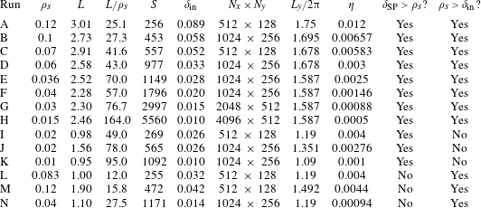
where this instability is expected to be active. We specifically wish to focus on the instability’s existence at modest, experimentally accessible, values of the Lundquist number. To this effect, we perform a series of runs as listed in table 1. Amongst other parameters, the table lists the length of the current sheet,
 $L$
, that is dynamically obtained during the nonlinear evolution of the primary tearing mode (which results from the collapse of the
 $X$
-point, as previously described). This length is measured using a full width at half-maximum estimateFootnote
5
(as is the current sheet thickness,
 $\unicode[STIX]{x1D6FF}$
) just before the plasmoid appears, and it is this length that is used to estimate the Lundquist number that is also listed in table 1 (the magnitude of the upstream magnetic field remains unchanged by the
 $X$
-point collapse).
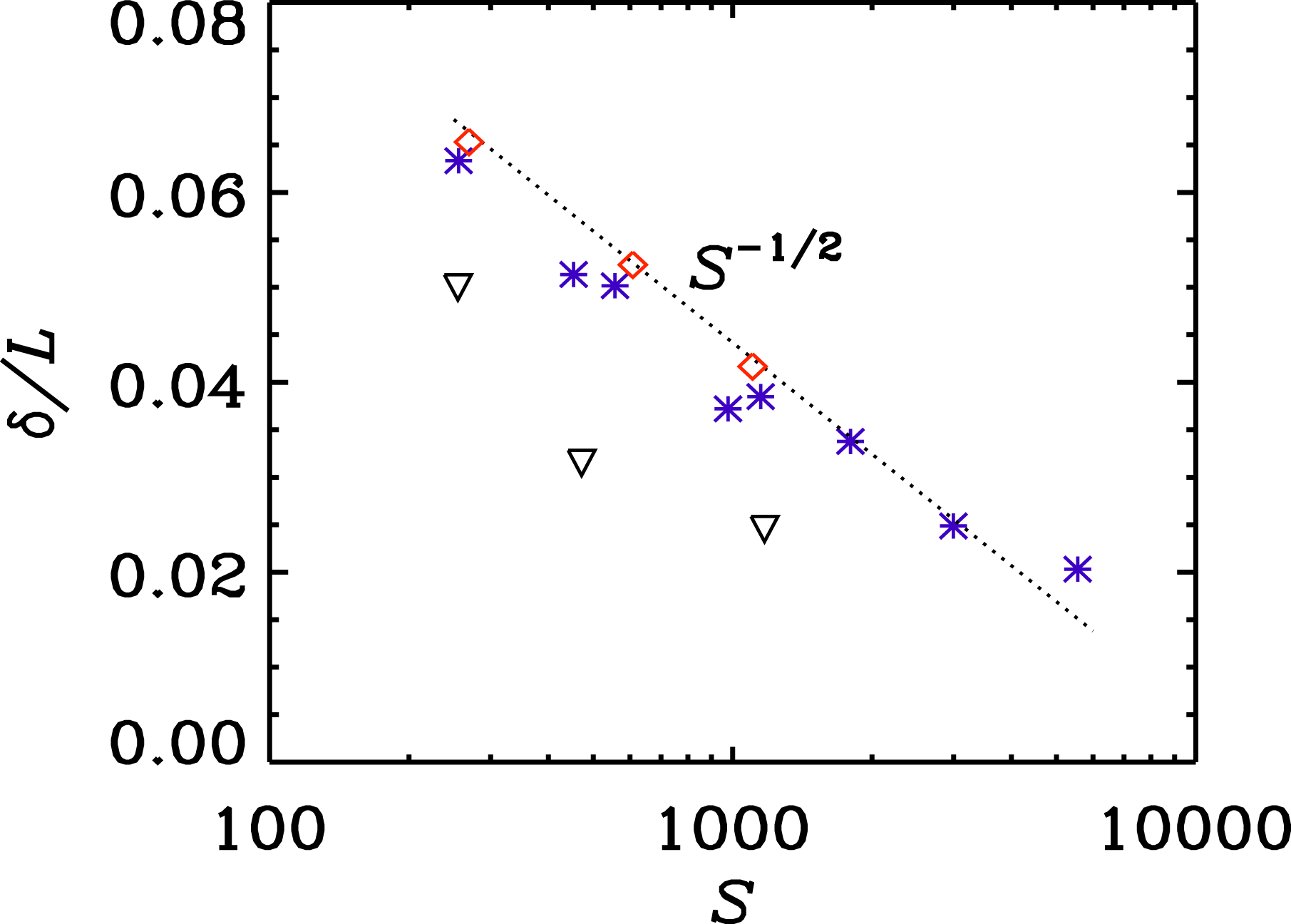
The ratio of current sheet width
 $\unicode[STIX]{x1D6FF}$
to its length
 $L$
against the Lundquist number
 $S$
is shown for Runs A through H (blue stars), I, J and K (red diamonds), and L, M and N (black inverted triangles). Refer to table 1 for details of these runs. The dotted line indicates an
 $S^{-1/2}$
slope, expected for Sweet–Parker current sheets.

Summary of all the runs discussed in the paper. The table lists the values of the sound Larmor radius
 $\unicode[STIX]{x1D70C}_{s}$
, length of the current sheet
 $L$
, their ratio
 $L/\unicode[STIX]{x1D70C}_{s}$
, Lundquist number
 $S$
, the inner boundary layer width
 $\unicode[STIX]{x1D6FF}_{\text{in}}$
(using (2.14)), the number of grid points employed
 $N_{x}\times N_{y}$
, the length of domain in the
 $y$
-direction,
 $L_{y}$
, resistivity
 $\unicode[STIX]{x1D702}$
and answers whether both constraints of the semi-collisional regime are satisfied or not for a given run.

The first step in the description of our results is the characterization of the current sheet that is dynamically obtained from the
 $X$
-point collapse of the primary tearing mode. The theory of the semi-collisional plasmoid instability laid out in § 2 assumes a SP sheet as the background equilibrium; and so it is important to determine whether indeed that is the case in our simulations. In figure 2, we plot
 $\unicode[STIX]{x1D6FF}/L$
as a function of the Lundquist number
 $S$
, obtained from all the runs. We find, as shown in figure 2 by the blue stars (Runs A to H) and red diamonds (Runs I, J, K), that the current sheets in these runs follow the SP scaling. The system in these runs is initially purely in the MHD regime as the inner boundary layer thickness of the primary tearing mode is larger than the kinetic scales. And thus, upon
 $X$
-point collapse of the MHD tearing mode, the current sheets that form are expected to follow the SP scaling (Loureiro et al.
Reference Loureiro, Cowley, Dorland, Haines and Schekochihin2005), which indeed bears out.
In the case of the three black inverted triangles shown in the figure 2, corresponding to Runs L, M and N, the ion sound Larmor radius
 $\unicode[STIX]{x1D70C}_{s}$
is set to be larger than the SP current sheet width (
 $\unicode[STIX]{x1D6FF}_{\text{SP}}$
). Thus, when
 $X$
-point collapse happens, these runs are affected by ion scale physics; unsurprisingly, the current sheets here do not follow the SP scaling. In summary, by the end of the collapse of the primary tearing mode and formation of the current sheet, the blue starred runs (Runs A to H) are in the semi-collisional regime (
 $\unicode[STIX]{x1D6FF}_{\text{SP}}>\unicode[STIX]{x1D70C}_{s}>\unicode[STIX]{x1D6FF}_{\text{in}}$
), the red diamond runs (Runs I, J, K) in the MHD regime (
 $\unicode[STIX]{x1D6FF}_{\text{SP}}>\unicode[STIX]{x1D6FF}_{\text{in}}>\unicode[STIX]{x1D70C}_{s}$
) and the black inverted triangles (Runs L, M and N) in a weakly collisional regime where a Sweet–Parker sheet no longer forms (
 $\unicode[STIX]{x1D70C}_{s}>\unicode[STIX]{x1D6FF}_{\text{SP}}>\unicode[STIX]{x1D6FF}_{\text{in}}$
).
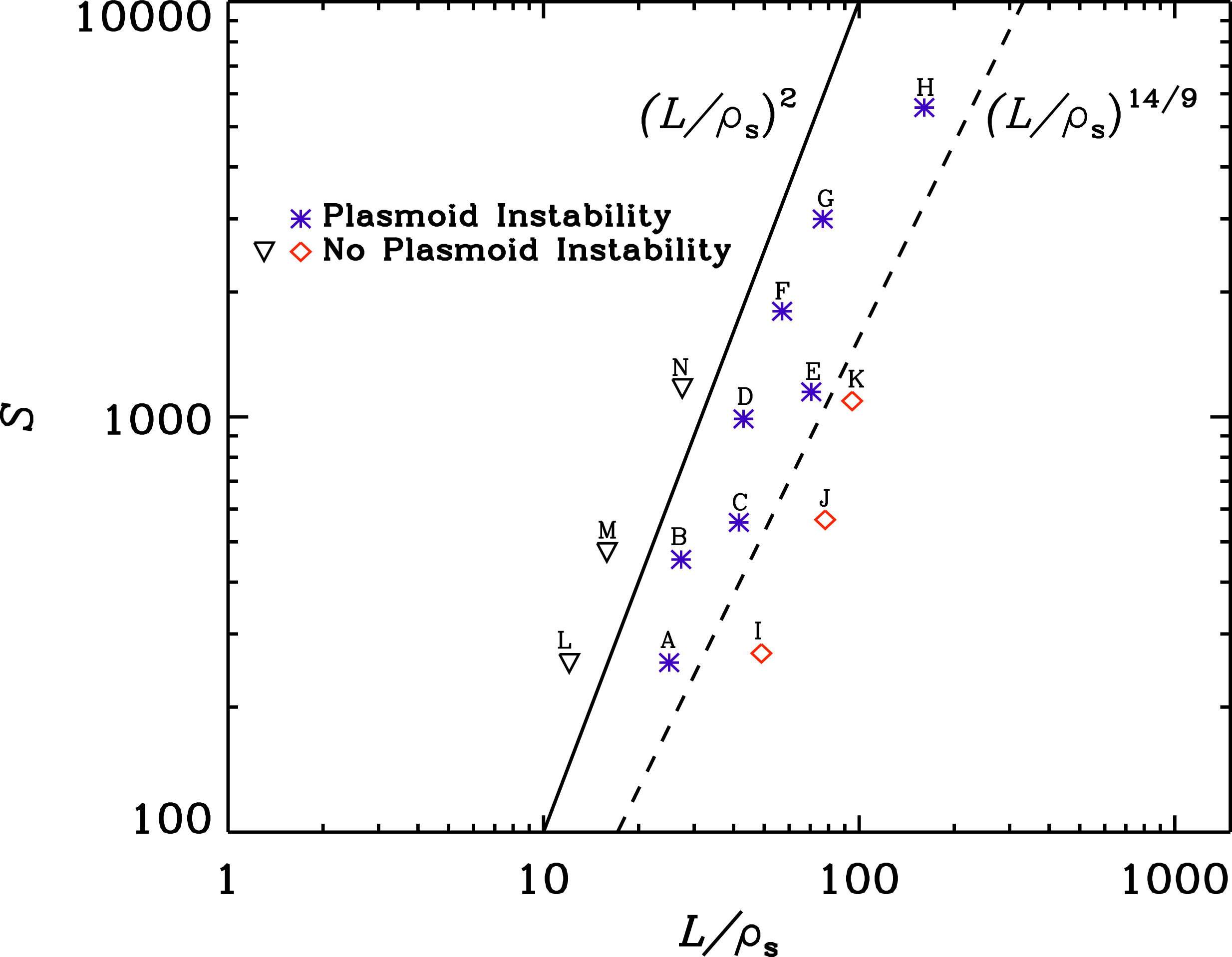
Reconnection phase diagram showing the semi-collisional regime marked out by the upper bound (
 $\unicode[STIX]{x1D6FF}_{\text{SP}}>\unicode[STIX]{x1D70C}_{s}$
; solid line) and lower bound (
 $\unicode[STIX]{x1D70C}_{s}>\unicode[STIX]{x1D6FF}_{\text{in}}$
; dashed line) as prescribed by (2.15). Blue stars denote simulations which show the plasmoid instability; red diamonds and black inverted triangles correspond to simulations which do not. The parameters (and other details) of each run can be looked up in table 1.

Next, we show whether or not the plasmoid instability is observed for a given run on the
 $S$
–
 $L/\unicode[STIX]{x1D70C}_{s}$
parameter space in figure 3. The two groups of runs represented by blue stars and red diamonds, which form SP current sheets, have
 $\unicode[STIX]{x1D70C}_{s}<\unicode[STIX]{x1D6FF}_{\text{SP}}$
(the symbols here match those in figure 2). Furthermore, in the case of the blue starred runs, upon the formation of the current sheet, the system becomes sensitive to the presence of
 $\unicode[STIX]{x1D70C}_{s}$
, as this kinetic scale is now larger than the semi-collisional inner boundary layer
 $\unicode[STIX]{x1D6FF}_{\text{in}}$
(corresponding to the newly formed SP layer) (see (2.8)). As a result, the plasmoid instability can arise, and indeed it does, as seen in Runs A to H (blue stars). On the other hand, in the case of Runs I, J, K (red diamonds),
 $\unicode[STIX]{x1D70C}_{s}$
is not only smaller that
 $\unicode[STIX]{x1D6FF}_{\text{SP}}$
, but is also smaller that
 $\unicode[STIX]{x1D6FF}_{\text{in}}$
and thus no plasmoids arise in these runs. The condition of
 $\unicode[STIX]{x1D70C}_{s}<\unicode[STIX]{x1D6FF}_{\text{in}}$
implies the absence of the plasmoid instability simply because the system continues to be in MHD regime and
 $S$
is much below the critical value of
 ${\sim}10^{4}$
required in MHD.
The Runs A to H which do result in plasmoid instability are within the two theoretical bounds of the semi-collisional regime marked by solid and dashed black lines (2.15). Runs I, J and K (where
 $\unicode[STIX]{x1D70C}_{s}<\unicode[STIX]{x1D6FF}_{\text{in}}$
) below the lower bound match roughly in
 $S$
with Runs A, C and E respectively; Runs L, M, N (where
 $\unicode[STIX]{x1D70C}_{s}>\unicode[STIX]{x1D6FF}_{\text{SP}}$
) above the upper bound, were performed to match in
 $S$
roughly with Runs A, B and E respectively. We find that neither of these two sets of runs yield the plasmoid instability. We conclude, therefore, that the theoretically prescribed bounds demarcating the semi-collisional regime are remarkably robust within the range of Lundquist numbers and Larmor radii that we have explored.
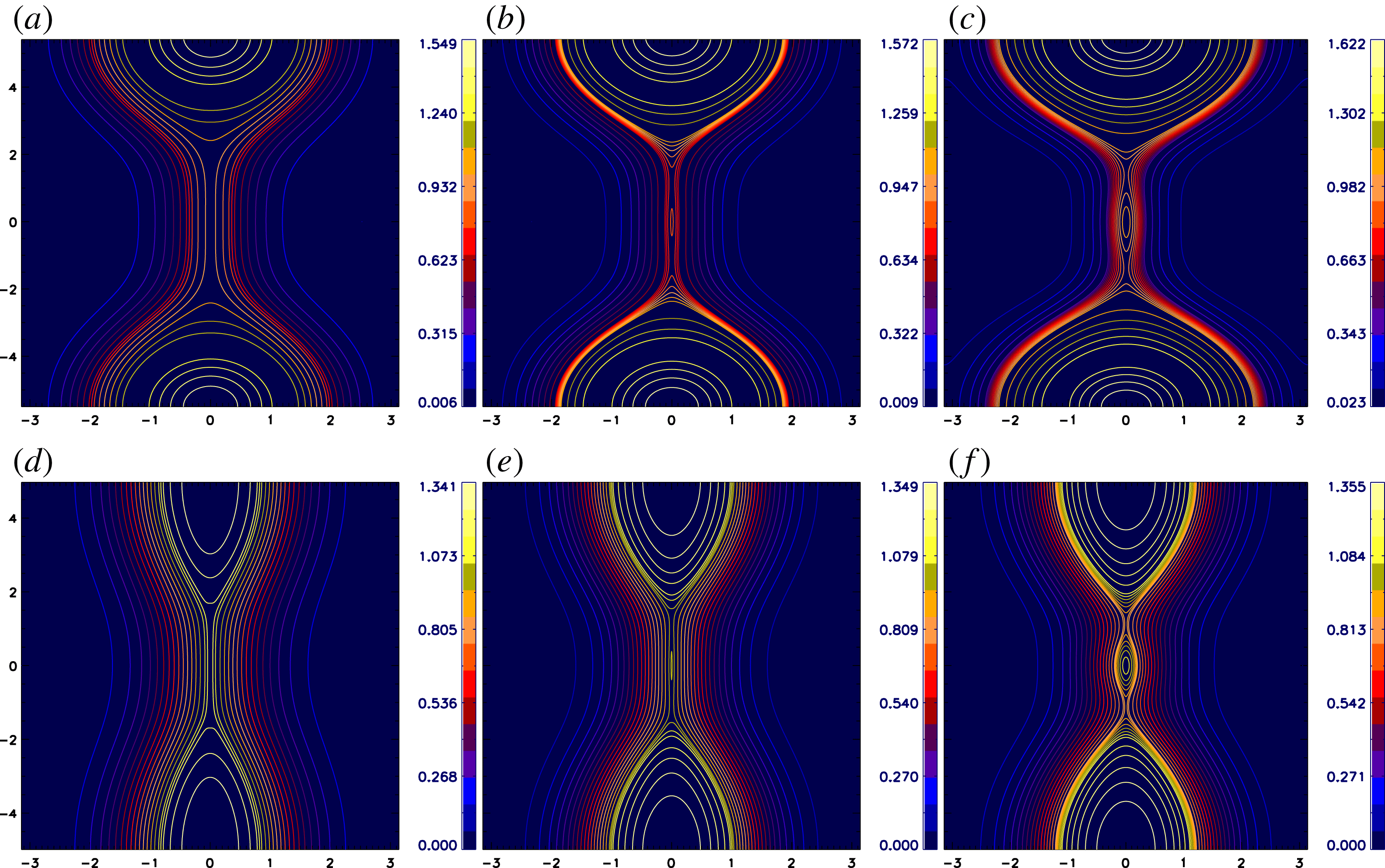
Contour plots of
 $A_{\Vert }$
for Run A (a–c) with lowest
 $S=256$
(and
 $L/\unicode[STIX]{x1D70C}_{s}=25$
), and Run H (d–f) with highest
 $S=5560$
(and
 $L/\unicode[STIX]{x1D70C}_{s}=164$
) at three different times: (a,d), just before the plasmoid forms; (b,e), in the early stages of plasmoid formation; and (c,f), when the plasmoid is in its nonlinear stage.

Further insight can be gained by visually analysing these runs. In particular it is of interest to visually compare Runs A and H, corresponding, respectively, to the lowest (
 $S=256$
) and highest (
 $S=5560$
) values of the Lundquist number at which we have observed the plasmoid instability. Figure 4 shows contour plots of
 $A_{\Vert }$
at three different times. The two leftmost panels (a,d) depict the system just before the plasmoid formation. The middle panels show the early stages of the plasmoid development; and the rightmost panels show the plasmoid well into the nonlinear stage. In both cases, note that in its early stage (b,e) the
 $y$
-extent of the plasmoid (roughly its linear wavelength) is much smaller than the length of the current sheet (to be discussed below). Also, due to the highly symmetric configuration of the magnetic field (and the intrinsic symmetry germane to the pseudo-spectral method that we employ), the plasmoid is stuck to the middle of the sheet. In a less constrained situation, we expect that this plasmoid would be ejected upwards or downwards, and subsequent plasmoids to be seeded until the system approaches saturation. It can be seen clearly that the gradient of
 $A_{\Vert }$
in the current sheet is larger in Run H compared to Run A, as expected given the order of magnitude difference in the values of their Lundquist numbers. Thus a curiosity is that even in the run with highest
 $S$
, only a single plasmoid forms. We will address this concern at a later point.
Another interesting comparison is between Runs E (
 $S=1149$
,
 $L/\unicode[STIX]{x1D70C}_{s}=70.5$
, blue star) and K (
 $S=1092$
,
 $L/\unicode[STIX]{x1D70C}_{s}=95$
, red diamond). As seen in figure 5, Run E shows a similar time evolution to that displayed by the runs in figure 4, with the current sheet becoming unstable to plasmoid formation. In Run K, on the other hand, the collapsed current sheet never goes unstable, and the primary tearing mode just proceeds to saturation. This is rather remarkable given how close in the phase space outlined by
 $S$
and
 $L/\unicode[STIX]{x1D70C}_{s}$
these two runs are (see figure 3).
Contour plots of
 $A_{\Vert }$
for Run E in the semi-collisional regime (a–c), with
 $S=1149$
and
 $L/\unicode[STIX]{x1D70C}_{s}=70.5$
; and for Run K in the MHD regime (d–f), with
 $S=1092$
and
 $L/\unicode[STIX]{x1D70C}_{s}=95$
, at three consecutive times from left to right.

Contour plots of
 $A_{\Vert }$
for Run N (in the weakly collisional regime), with
 $S=1171$
and
 $L/\unicode[STIX]{x1D70C}_{s}=27.5$
, at three consecutive times from (a) to (c).

In figure 6, we also show a run from the weakly collisional regime, with the parameters
 $S=1171$
and
 $L/\unicode[STIX]{x1D70C}_{s}=27.5$
(Run N). There is no plasmoid formation as expected. It is interesting to note that the current density forms an
 $X$
-point, as seen from figure 6(a), which is consistent with what is expected in such a regime. The
 $X$
-point later transitions to a double-structured current sheet, which retains a sharp peak at its centre.
Wavenumber measured from the width of the arising plasmoid in Runs A–G, plotted against the theoretical prediction (2.13).

It is noteworthy that all of the runs in this regime are at Lundquist numbers much lower than the MHD critical value of order
 ${\sim}10^{4}$
. The lowest
 $S$
at which a simulation (Run A) obtains the plasmoid instability is 250. As one decreases the value of
 $S$
even further we find in our simulations that width of the primary island becomes as large as the simulation domain before any plasmoid is observed. In a less constrained system it is possible that the plasmoid instability remains active at even lower values of
 $S$
.
The linear regime of the plasmoid instability is very short lived: it ends once the plasmoid becomes larger than the inner boundary layer. Although this layer is resolved in all our simulations, the number of grid points in the inner layer is not sufficiently large to be able to trace a long enough evolution in the linear regime. Thus, linear growth rate measurements cannot reliably be obtained. However, the wavenumber is a straightforward quantity to measure. An intriguing observation is that only one single plasmoid arises in the Runs A–H. These runs range over a decade in Lundquist number and thus the expected number of plasmoids varies by a factor of
 ${\gtrsim}3$
from the run with lowest
 $S$
to the run with highest
 $S$
, according to (2.13). That is not what we obtain, suggesting disagreement with the linear predictions. This leads one to wonder why it is that the lower bound,
 $S>(L/\unicode[STIX]{x1D70C}_{s})^{14/9}$
, is validated so well (figure 3), given that its validity relies on the scalings for
 $k_{\text{max}}$
(and
 $\unicode[STIX]{x1D6FE}_{\text{max}}$
) being correct.
To address this issue, we proceed as follows. For each run, instead of counting the number of plasmoids to estimate the wavenumber, we compute it from the measurement of the
 $y$
-extent of the plasmoid (full width at half-maximum of the island in
 $A_{\Vert }$
) at the earliest possible stages of its appearance. We find that this measurement of the wavenumber does follow the theoretical scaling rather well, as shown in figure 7. We suspect that the explanation for this result lies in the effects of spatial inhomogeneity in the direction along the sheet, as well as flows and reconnected component of the magnetic field. None of these effects is negligible at these low values of the Lundquist number, but they are all neglected in the theoretical derivation. This argument is strengthened further by the results shown in the Appendix. The important observation, however, is that the plasmoid that does form has the correct wavenumber as predicted by linear theory.
6 Discussions and conclusions
In this paper, we have investigated, analytically and numerically, the semi-collisional regime of the plasmoid instability – an extension to a Sweet–Parker sheet of the semi-collisional tearing mode (Drake & Lee Reference Drake and Lee1977; Cowley, Kulsrud & Hahm Reference Cowley, Kulsrud and Hahm1986; Zocco & Schekochihin Reference Zocco and Schekochihin2011). We employ a reduced kinetic formalism obtainable from the gyrokinetic formalism via asymptotic expansion in low plasma
 $\unicode[STIX]{x1D6FD}$
(Zocco & Schekochihin Reference Zocco and Schekochihin2011). The simulations are carried out with the code Viriato (Loureiro et al.
Reference Loureiro, Dorland, Fazendeiro, Kanekar, Mallet, Vilelas and Zocco2016). This regime is analytically predicted to occupy a significant sliver of the reconnection phase diagram defined by a lower bound
 $S>(L/\unicode[STIX]{x1D70C}_{s})^{14/9}$
and an upper bound
 $S<(L/\unicode[STIX]{x1D70C}_{s})^{2}$
. Our numerical simulations show that these bounds are remarkably robust: runs which fall within these two bounds yield the plasmoid instability, and vice versa. The instability arises at much lower values of the Lundquist numbers than the MHD analogue; as low as
 $S\sim 250$
. We are limited in our exploration of even lower values of
 $S$
by our simulation set-up. Thus, we do not rule out the formation of plasmoids for
 $S<250$
in less constrained systems; indeed, we speculate that this regime could also potentially explain formation of plasmoids in recent reconnection experiments (Jara-Almonte et al.
Reference Jara-Almonte, Ji, Yamada, Yoo and Fox2016; Hare et al.
Reference Hare, Lebedev, Suttle, Loureiro, Ciardi, Burdiak, Chittenden, Clayson, Eardley and Garcia2017a
,Reference Hare, Suttle, Lebedev, Loureiro, Ciardi, Burdiak, Chittenden, Clayson, Garcia and Niasse
b
, Reference Hare, Suttle, Lebedev, Loureiro, Ciardi, Chittenden, Clayson, Eardley, Garcia and Halliday2018). In Magpie, for example, we find from table I in Hare et al. (Reference Hare, Suttle, Lebedev, Loureiro, Ciardi, Chittenden, Clayson, Eardley, Garcia and Halliday2018) that
 $S\approx 120$
and
 $L/d_{i}\approx 18$
. If we were to consider the relevant kinetic scale to be
 $d_{i}$
instead of
 $\unicode[STIX]{x1D70C}_{s}$
, then the value of these parameters (
 $S$
and
 $L/d_{i}$
) satisfy the condition for the semi-collisional regime and fall within its bounds. Note that in the collisionless (or weakly collisional) regime, plasmoids arise only when
 $L/\unicode[STIX]{x1D70C}_{s}$
is larger than a value of about
 ${\sim}50$
(an empirical value seen in simulations) (Ji & Daughton Reference Ji and Daughton2011), whereas the semi-collisional regime seems to offer no hard lower bound. Further, with the validation of the existence of this regime, the reconnection phase diagram (figure 1 in Ji & Daughton Reference Ji and Daughton2011) would be modified. The lower bound of this regime, governed by either
 $S=(L/\unicode[STIX]{x1D70C}_{s})^{14/9}$
or
 $S=(L/\unicode[STIX]{x1D70C}_{s})^{8/5}$
would now cut across the two lines – one line representing the critical Lundquist number for MHD plasmoid instability (
 $S=S_{c}$
) and then a second line representing the lower bound of the multiple
 $X$
-line hybrid regime (
 $S=L\sqrt{S_{c}}/2\unicode[STIX]{x1D70C}_{s}$
).
The numerical experiments reported here are limited in that the amount of flux to reconnect is finite, and the simulation box is periodic. As such, (statistical) steady state reconnection cannot be attained, thereby preventing us from numerically answering the important question of what the reconnection rate is in the semi-collisional plasmoid regime. However, theoretically we may expect the following. In the phase-space diagram of figure 3, assume that the initial system, with a certain
 $S$
,
 $L$
and
 $\unicode[STIX]{x1D70C}_{s}$
, is in the semi-collisional regime. As the plasmoid instability unfolds, we expect that smaller, interplasmoid current sheets will arise. These will necessarily have a smaller length,
 $L^{\prime }\sim L/N$
, where
 $N$
is the number of primary plasmoids. Each of these interplasmoid current sheets now defines a reconnecting site which can be located in the reconnection phase diagram. Since
 $\unicode[STIX]{x1D70C}_{s}$
and
 $\unicode[STIX]{x1D702}$
are fixed, and assuming that
 $V_{A}$
is the same in these daughter sheets, the only parameter that has changed is the length, from
 $L$
to
 $L^{\prime }$
. This means a diagonal displacement in the direction of smaller
 $L/\unicode[STIX]{x1D70C}_{s}$
from the initial point in that diagram; the slope of that diagonal is 1, because both axes are linearly proportional to
 $L$
. If the new position in this diagram remains in the semi-collisional regime, each interplasmoid current sheet is still unstable to the semi-collisional plasmoid instability. The process then repeats (i.e. the plasmoid hierarchy unfolds further) until arriving at an interplasmoid current sheet which is now short enough to be outside of the semi-collisional bounds. Inevitably, therefore, this lands the system to the left of the
 $S\sim (L/\unicode[STIX]{x1D70C}_{s})^{2}$
bound, i.e. the collisionless regime, where the expected reconnection rate is
 ${\sim}0.1\unicode[STIX]{x1D70F}_{A}^{-1}$
. Defining
 $\unicode[STIX]{x1D706}_{c}=(L_{c}/\unicode[STIX]{x1D70C}_{s})$
as an empirical scale separating the single from the multiple
 $X$
-line collisionless regimes (numerically observed to be
 ${\sim}50$
), we conclude that the system finally lands in either the multiple, or single,
 $X$
-line collisionless regime depending on whether it is initially above or below the diagonal line
 $S\sim \unicode[STIX]{x1D706}_{c}(L/\unicode[STIX]{x1D70C}_{s})$
, (which intersects the line
 $S\sim (L/\unicode[STIX]{x1D70C}_{s})^{2}$
at
 $(L/\unicode[STIX]{x1D70C}_{s})=\unicode[STIX]{x1D706}_{c}$
) in the reconnection phase space diagram.
Finally, let us outline some general arguments for the case when, unlike our simulations, the global Lundquist number of the system is so large that a Sweet–Parker current sheet may not be able to form dynamically. Consider then a forming current sheet, and assume for simplicity that the characteristic time at which it is forming is Alfvénic,
 $\unicode[STIX]{x1D70F}_{A}=L/V_{A}$
. At any given moment of time, we parameterize the forming current sheet aspect ratio as
 $a/L=S^{-\unicode[STIX]{x1D6FC}}$
(Pucci & Velli Reference Pucci and Velli2014), where
 $a$
is the current sheet width, and
 $\unicode[STIX]{x1D6FC}$
is a number such that
 $0<\unicode[STIX]{x1D6FC}<1/2$
, with
 $\unicode[STIX]{x1D6FC}=1/2$
representing a Sweet–Parker sheet (which the system presumably never gets to).
Using (2.6) (for a Harris-type sheet) we see that the growth rate of the most unstable semi-collisional mode exceeds the current sheet formation rate (Alfvénic) when
 $$\begin{eqnarray}\unicode[STIX]{x1D6FE}_{\text{max}}\unicode[STIX]{x1D70F}_{A}\sim (\unicode[STIX]{x1D70C}_{s}/L)^{2/3}S^{-1/3+2\unicode[STIX]{x1D6FC}}\gtrsim 1.\end{eqnarray}$$
This expression constrains the relationship between
 $S$
and
 $L/\unicode[STIX]{x1D70C}_{s}$
, for any value of
 $\unicode[STIX]{x1D6FC}$
, to attain Alfvénic growth at that value of
 $\unicode[STIX]{x1D6FC}$
. In addition, we must further require that this mode (the most unstable semi-collisional mode) is indeed in the semi-collisional regime, i.e.
 $\unicode[STIX]{x1D6FF}_{\text{in},\text{max}}^{SC}<\unicode[STIX]{x1D70C}_{s}$
. This leads to,
 $$\begin{eqnarray}(\unicode[STIX]{x1D70C}_{s}/L)^{1/9}S^{-(2\unicode[STIX]{x1D6FC}/3)-2/9}<\unicode[STIX]{x1D70C}_{s}/L.\end{eqnarray}$$
These two expressions intersect when
 $\unicode[STIX]{x1D6FC}=1/3$
. That is, if
 $\unicode[STIX]{x1D6FC}<1/3$
, the relationship that
 $S$
and
 $L/\unicode[STIX]{x1D70C}_{s}$
must satisfy to yield Alfvénic growth is given by (6.1); if instead
 $\unicode[STIX]{x1D6FC}>1/3$
, then it is sufficient to satisfy (6.2) to attain Alfvénic growth.Footnote
6
A detailed analysis of all different possibilities that are encountered as
 $\unicode[STIX]{x1D6FC}$
increases is beyond the scope of this paper and will be left to future work. Generally, for
 $\unicode[STIX]{x1D6FC}<1/3$
, the condition for the fastest semi-collisional mode to become faster than Alfvénic becomes progressively less demanding on
 $S$
. Consider the particularly interesting case where
 $\unicode[STIX]{x1D6FC}$
reaches the value of
 $1/3$
. At this value, we must have
 $S>(L/\unicode[STIX]{x1D70C}_{s})^{2}$
for the semi-collisional mode to both exist and be super-Alfvénic. Remarkably,
 $\unicode[STIX]{x1D6FC}=1/3$
is the value at which the fastest growing MHD mode becomes Alfvénic (Pucci & Velli Reference Pucci and Velli2014). The condition for that mode to indeed be in the MHD regime is, unsurprisingly, just the reverse of the above,
 $S<(L/\unicode[STIX]{x1D70C}_{s})^{2}$
. So, in this case (
 $\unicode[STIX]{x1D6FC}=1/3$
), the outcome is particularly simple: if
 $S>(L/\unicode[STIX]{x1D70C}_{s})^{2}$
the forming sheet would be disrupted by a semi-collisional mode, and one might expect the reconnection rate to ensue to be
 $0.1\unicode[STIX]{x1D70F}_{A}^{-1}$
as discussed above; if, instead
 $S<(L/\unicode[STIX]{x1D70C}_{s})^{2}$
then the sheet would be disrupted by an MHD mode, and the reconnection rate would presumably be
 $S_{c}^{-1/2}\unicode[STIX]{x1D70F}_{A}^{-1}\sim 0.01\unicode[STIX]{x1D70F}_{A}^{-1}$
(unless a transition to the semi-collisional regime occurs during the plasmoid cascade – see footnote 4 on page 5). For example, in the solar corona, where
 $S\sim 10^{13}$
and
 $L/\unicode[STIX]{x1D70C}_{s}\sim 10^{7}$
, we see that the MHD mode would win.
Acknowledgements
We thank E. Tolman and R. White for helpful discussions. This work was supported by the NSF-DOE Partnership in Basic Plasma Science and Engineering, Award no. DE-SC0016215. The simulations presented in this paper were performed on the MIT-PSFC partition of the Engaging cluster at the MGHPCC facility (www.mghpcc.org) which was funded by DoE grant no. DE-FG02-91-ER54109. We also acknowledge the usage of Stampede cluster in Texas under the allocation TG-PHY140041.
Appendix. Semi-collisional tearing mode scalings in an SP sheet
To confirm the validity of the analytical derivation of § 2, and the ability of the Viriato code to recover the scalings predicted there, we have performed a set of simulations whose key difference from those reported in the main text lies in the fact that the thickness of initial magnetic profile is now the Sweet–Parker width,
 $L_{y}S^{-1/2}$
, as is assumed throughout § 2. This initial configuration is not an exact Sweet–Parker sheet because it lacks both the appropriate flows, and the reconnected component of the magnetic field; these are also simplifications adopted in the theoretical derivation, and which can be shown analytically to be justifiable (Loureiro et al.
Reference Loureiro, Schekochihin and Cowley2007, Reference Loureiro, Schekochihin and Uzdensky2013).

All possible modes are seeded by the introduction of a small amplitude random perturbation at
 $t=0$
. After an initial transient, we observe the exponential growth of a single mode – the most unstable perturbation. The growth rate and wavenumber (determined by counting the number of arising plasmoids) of this mode are plotted in figure 8. Excellent agreement with the theoretical scalings of (2.12) and (2.13) is observed.