I. INTRODUCTION
Carbon, often referred to as ‘king of the elements’, has attracted tremendous research attentions.Reference Dai, Chang, Baek and Lu1 Graphite, diamond, and amorphous carbon are the three best known carbon materials.Reference Su and Schlögl2 The physical and chemical properties of carbon materials vary widely with carbon bonding forms, for example, the well-known sp 2 and sp 3 hybridization.Reference Su and Schlögl2–Reference Zheng, Luo, Lv, Wang and Yang4 According to dimensionalities, nano-sized carbons with sp 2 hybridization structure can be classified into zero, one and two dimensional (0D, 1D, and 2D) carbon nanomaterials.Reference Candelaria, Shao, Zhou, Li, Xiao, Zhang, Wang, Liu, Li and Cao3 The most classical representative of 0D nanocarbons is fullerene (C60), which was discovered in 1985 and was awarded the Nobel Prize in 1996.Reference Kroto, Heath, O’Brien, F Curl and Smalley5 The discovery of C60 has created a new branch of carbon chemistry. Carbon nanotube is a typical representative of 1D nanocarbon, and it was discovered in 1991 by Iijima.Reference Iijima and Ichihashi6 Carbon nanotubes consist of carbon hexagons arranged in a concentric manner with both ends often capped by fullerene-like hemispheres. Graphene, a perfect 2D nanocarbon, which can be regarded as a single-atom-thick carbon nanosheet, was first isolated from graphite by Geim AK and his co-workers in 2004, and this discovery won the 2010 Noble Prize in Physics.Reference Novoselov, Geim, Morozov, Jiang, Zhang, Dubonos and Firsov7 The discoveries of these three types of nanocarbons have greatly boosted the development of materials science and nanotechnology.Reference Kroto, Heath, O’Brien, F Curl and Smalley5–Reference Novoselov, Geim, Morozov, Jiang, Zhang, Dubonos and Firsov7
Amorphous carbon is another important carbon form with sp 3 hybridization, which can be obtained via pyrolysis of various organic precursors. Through certain synthetic strategies, amorphous carbon materials with various dimensions, including 0D nanospheres,Reference Yu, Wang, Huang, Shen and Kang8 1D nanofibers,Reference Zhang, Aboagye, Kelkar, Lai and Fong9 and 2D nanosheetsReference Yu, Zhao, Lv, Liang, Zhan, Bai, Huang, Shen and Kang10 can be achieved. Besides, they also exhibit tunable properties,Reference Dutta, Bhaumik and Wu11 like adjustable porosities and diverse surface functionality modification.Reference Xu, Yu, Liang, Bai, Huang and Kang12,Reference Paraknowitsch and Thomas13
In general, carbon nanomaterials, including sp 2-hybridized nanocarbons and amorphous nanocarbons, have large specific surface area, excellent mechanical properties, superior electrical conductivity as well as unique chemical and physical properties.Reference Su and Schlögl2,Reference Candelaria, Shao, Zhou, Li, Xiao, Zhang, Wang, Liu, Li and Cao3,Reference Zhao, Hu, Hu, Cheng, Shi and Qu14,Reference Wang, Xin and Wang15 Therefore, carbon nanomaterials have been applied in many fields. For example, graphene can be used in the electronic industry,Reference Rao, Biswas, Subrahmanyam and Govindaraj16,Reference Avouris17 biotechnology industry,Reference Akhavan, Ghaderi, Aghayee, Fereydooni and Talebi18 3D printing,Reference Kim, Chang, Kim, Yang, Han, Lee, Kim and Seol19 and energy storage and conversion systems.Reference Lin, Zeng, Gui, Tang, Zou and Cao20–Reference Liu, Zhang, Song and Li22 Typically, carbon nanomaterials can serve as electrode materials of energy storage devices, such as lithium-ion batteries,Reference Xin, Guo and Wan23 sodium-ion batteries,Reference Wenzel, Hara, Janek and Adelhelm24 lithium–sulfur batteries,Reference Ji, Lee and Nazar25 and supercapacitors.Reference Zhu, Murali, Cai, Li, Suk, Potts and Ruoff26 The large specific surface area of carbon nanomaterials can provide abundant active sites for electrochemical reaction (such as lithium-ion storage and sodium-ion storage), thus contributing to high specific capacity.Reference Xin, Guo and Wan23–Reference Zhu, Murali, Cai, Li, Suk, Potts and Ruoff26 In addition, carbon nanomaterials often possess an advanced porous structure with pore diameters ranging from several angstroms to tens of nanometers. The porous structure can provide rapid transport paths for electrolyte ions and shorten the ion diffusion length.Reference Su and Schlögl2,Reference Zheng, Luo, Lv, Wang and Yang4,Reference Wu, Yang, Wang and Hu27 As a result, superior rate performance can be achieved. Furthermore, the excellent mechanical properties of nanocarbons enable facile strain relaxation, guaranteeing structural stability of electrodes during electrochemical cycles.Reference Zhang, Aboagye, Kelkar, Lai and Fong9,Reference Rao, Biswas, Subrahmanyam and Govindaraj16,Reference Xin, Guo and Wan23 However, due to the huge surface area and strong π–π interactions or van der Waals interactions, carbon nanomaterials always suffer from serious aggregation and stacking problems, which induce the active surface area loss and hinder the smooth diffusion of electrolyte ions.Reference Zheng, Zhang, Pei, Dai, Fang, Wang and Zheng28,Reference Zhao, Zhang, Huang, Tian, Nie, Peng and Wei29 These problems damage the electrochemical performance of nanocarbon electrodes. Therefore, to make full use of surface area and improve electrochemical performance, it is critical to prevent nanocarbon electrodes from aggregation and stacking.
In recent years, researchers have proved that constructing hierarchical architectures which consist of nanocarbon subunits is an effective strategy to address above mentioned problems. Many hierarchically structured carbon nanomaterials have been designed and applied as electrode materials of energy storage devices. Structure hierarchy is quite important in the biological world. It shows complex architecture at multi length scale. Inspired by nature, hierarchically structured materials have been developed in recent years. Among them, hierarchically structured carbon nanomaterials (HSCNs) have received tremendous research attentions due to their intriguing properties. Normally, HSCNs consist of a primary carbon matrix structure and nanocarbon subunits, such as 0D carbon nanospheres, 1D carbon nanofiber/nanotube and 2D carbon nanosheets. Such subunits are ‘grown’ on a pre-synthesized carbon matrix or integrated in a specific manner to form the carbon matrix structure. The hierarchical structure of HSCNs can alleviate aggregation and stacking issues, and thus reduce active surface loss of nanocarbon subunits.Reference Zheng, Zhang, Pei, Dai, Fang, Wang and Zheng28,Reference Zhao, Zhang, Huang, Tian, Nie, Peng and Wei29 Moreover, HSCNs own interconnected porous network, which can facilitate the rapid diffusion of electrolyte ions. Therefore, the hierarchical structure enables taking full advantages of the unique properties of carbon nanomaterials. As a result, improved electrochemical performance, including specific capacity and rate capabilities of nanocarbons can be achieved.Reference Zheng, Zhang, Pei, Dai, Fang, Wang and Zheng28
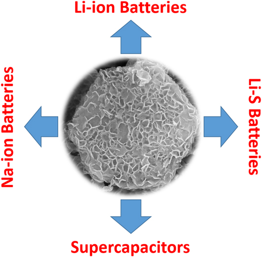
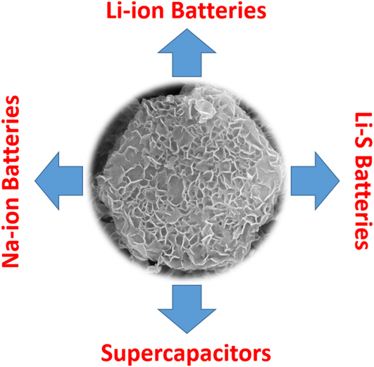
Three main factors need to be considered for the successful design and synthesis of HSCNs. First is the structure stability of the hierarchical carbon architecture. As stated above, if the carbon matrix structure is presynthesized, it should have good mechanical strength to maintain the structure stability. If the carbon matrix structure is constructed by the nanocarbon subunits, the subunits should have excellent mechanical properties, and are integrated in a firm and steady way. Second is the uniform growth of nanocarbon subunits on the carbon matrix structure through certain synthesis methods, which benefit for ion high efficient transportation. Third is the porosity in the carbon matrix structure and in nanocarbon subunits, which is significant to provide adequate energy storage sites. In this review, we make a systematic summary and review about those research on hierarchical structure design of carbon nanomaterials and their electrochemical energy storage applications, including lithium-ion batteries (LIBs), sodium-ion batteries (SIBs), lithium–sulfur (Li–S) batteries and supercapacitors (Illus. 1), and also comment the challenges and future development trends of HSCNs.
HSCNs for different electrochemical energy storage applications.
II. HIERARCHICALLY STRUCTURED NANOCARBONS FOR LIBS
LIBs have been widely used in portable electronic devices and electric vehicles. LIBs are made up of cathode, anode, separator and electrolyte. LiCoO2, LiMn2O4, and LiFePO4 are common materials which have been studied and applied as cathode for LIBs.Reference Doughty and Roth30 The most popular anode material for LIBs is graphite, a commercially available soft carbon with high crystalline degree. Unfortunately, the theoretical specific capacity of graphite is 372 mA h/g, which cannot meet the requirement in practical application of LIBs.Reference Xie, He, Feng, Xu, Cui, Zhang, Yan, Carreon, Liu and Wang31 In addition, the rate performance of graphite is far from satisfaction.Reference Dong, Yu, Wang, Liu, Wang, Zhao and Qiu32
Nanocarbon materials, such as carbon nanospheres, carbon nanotube, graphene and carbon nanosheets, are promising candidates to replace graphite and boost electrochemical performance of LIBs.Reference Su and Schlögl2,Reference Zhao, Hu, Hu, Cheng, Shi and Qu14,Reference Lin, Zeng, Gui, Tang, Zou and Cao20,Reference Xin, Guo and Wan23,Reference Zheng, Zhang, Pei, Dai, Fang, Wang and Zheng28 However, the aggregation and stacking problems of nanocarbons cause a significant irreversible capacity loss (>50%) and damage its rate performance.Reference Yen, Tsai, Zhou, Holby, Choudhury, Chen, Adamska, Tretiak, Sanchez, Iyer, Zhang, Zhu, Lin, Dai, Wu and Wang33 Designing low-dimensional hierarchical architecture which consists of nanocarbon subunits can greatly improve LIB performance of carbon nanomaterials.
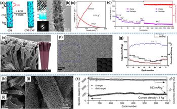
Goodenough et al.Reference Chen, Li, Park, Song, Hong, Zhou, Mai, Huang and Goodenough34 designed a 1D hierarchical carbon nanofiber-carbon nanotube hybrid (CNF-CNT) for the LIB anodes. The CNTs was grown on the surface of N-doped CNFs via in situ chemical vapor deposition method [Fig. 1(a)]. The CNF-CNT hybrid has a super high specific Brunauer–Emmett–Teller (BET) surface area of 1840 m2/g and a total pore volume of 1.21 m3/g. In this structure, the CNTs occupy the space between the CNFs and thus retain accesses in all directions for the electrolyte. The outside diameters of CNTs were about 30 nm and the diameter of CNF was about 260 nm [Fig. 1(b)]. The hybrid materials possess abundant pores with size blow 2 nm. When applied as anode materials of LIBs, the CNF-CNT composite delivered an initial discharge capacity of 2458 mA h/g and a charge capacity of 1530 mA h/g with an initial coulombic efficiency (ICE) of 62% [Fig. 1(c)]. No obvious discharge platform can be observed from the charge–discharge profile in the first cycle. The large irreversible capacity comes from the formation of solid electrolyte interface (SEI) layer and electrolyte decomposition in the first cycle. Because of the hierarchical structure, the CNF-CNT exhibited an excellent rate capability. Even at a high current density of 8 A/g, the discharge capacity still maintained at 320 mA h/g [Fig. 1(d)]. Zhao et al.Reference Fang, Lv, Che, Wu, Zhang, Gu, Zheng and Zhao35 designed a mesoporous carbon hollow tube array via a controlled low concentration monomicelle close-packing assembly approach [Fig. 1(e)]. Anodic aluminum oxide (AAO) membranes are used as a substrate to provide a large surface area for assembling and mass production. The obtained hollow tube consisted of 2D thin carbon nanosheets with 3 graphene layers, and the diameter of these carbon tubes was ∼400 nm. In this structure, the carbon layer displayed mesostructure, whose average pore size and wall thickness was ∼9 and ∼4 nm, respectively [Fig. 1(f)]. Interestingly, a bowl-like structure in the carbon nanosheet was obtained from the carbonization of organic precursor at high temperature [inset of Fig. 1(f)]. The atomic flat carbon layers with mesopores provide a huge active area for lithium-ion storage and intercalation, while the mesopores perpendicular to the carbon layer promote efficient ion diffusion as well as improve volume expansion flexibility. The discharge capacity was 3535 mA h/g and the ICE is about 26% at a current density of 100 mA/g. When the current density increased to 5 A/g, this unprecedented hierarchical carbon still can deliver a capacity of 370 mA h/g. This case is representative in terms of optimizing lithium-ion storage and rate capacity by introducing unique hierarchical structure in carbon electrodes. Zheng et al.Reference Zheng, Zhang, Pei, Dai, Fang, Wang and Zheng28 constructed a hierarchical porous carbon microrods (HPCMs) for LIB anodes. The HPCMs were composed of vertically aligned graphene-like nanosheets, and they were fabricated by using Mg(OH)2 templating method [Figs. 1(h)–1(j)]. The special design can successfully alleviate stacking problem of 2D nanocarbon. To construct HPCMS, MgO nanorods were simply treated with water, and thus a hierarchical structure of Mg(OH)2 microrods composed of vertically aligned ultrathin Mg(OH)2 nanosheets were prepared. Then the mixture of hierarchical Mg(OH)2 microrods and dopamine (which was used as carbon precursor) was heated under 900 °C. After removal of the template and further heat treating process at 1000 °C (to increase the electric conductivity), the HPCMs were finally obtained. The resulted HPCMs possess porous structure with BET surface area of 1423 m2/g and pore volume of 2.46 m3/g. The pore size distributed at ∼13 nm and the thickness of the carbon nanosheets grown on the surface of HPCMs was ∼2 nm. Such high surface and advanced porous structure made HPCMs a very promising candidate as anode of LIBs. The first discharge and charge capacity of HPCMs were 3382 and 1150 mA h/g, with an ICE of 34% (current density: 0.1 A/g). In the long-term cycling testing, HPCMs delivered a reversible capacity of 1150 mA h/g after 700 cycles even at a high current density of 1 A/g [Fig. 1(k)]. The superior electrochemical performance of HPCMs demonstrated that the oriented hierarchical structures could provide more favorable mass transport and ion diffusion pathways.
(a) Schematic of the activated N-doped hollow CNT-CNF hybrid material designReference Chen, Li, Park, Song, Hong, Zhou, Mai, Huang and Goodenough34; (b) TEM image of CNT-CNF hybridReference Chen, Li, Park, Song, Hong, Zhou, Mai, Huang and Goodenough34; (c) Charge–discharge curvesReference Chen, Li, Park, Song, Hong, Zhou, Mai, Huang and Goodenough34 and (d) Rate performance of CNT-CNF.Reference Chen, Li, Park, Song, Hong, Zhou, Mai, Huang and Goodenough34 (e) SEM images and schematic (inset) of the carbon hollow tubeReference Fang, Lv, Che, Wu, Zhang, Gu, Zheng and Zhao35; (f) TEM image of the carbon hollow tube and illustration of bowl-like mesostructured (inset)Reference Fang, Lv, Che, Wu, Zhang, Gu, Zheng and Zhao35; (g) Rate performance of the carbon hollow tube.Reference Wang, Yu, He, Kaneti, Han, Sun, He and Xiang36 (h), (i) and (j) SEM images of HPCMs at different magnificationsReference Zheng, Zhang, Pei, Dai, Fang, Wang and Zheng28; (k) Cycle performance of HPCMs at a current density of 1 A/g.Reference Zheng, Zhang, Pei, Dai, Fang, Wang and Zheng28

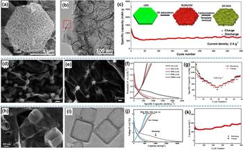
Wang et al.Reference Wang, Yu, He, Kaneti, Han, Sun, He and Xiang36 constructed a 2D hierarchical carbon architecture (2D-HCA) by utilizing an eco-friendly method. In 2D-HCA, graphene-like carbon nanosheets (2D) with a size of ∼150 nm grew on the surface of 2 μm-wide hexagonal carbon nanoplates (2D), building a hierarchical structure [Figs. 2(a) and 2(b)]. The carbon nanosheet effectively prevent stacking and aggregation of nanocarbon subunits. The 2D hierarchical structure consisted of 2D nanocarbon subunits which possessed a high surface (1363 m2/g), interconnected porous structure and abundant heteroatom doping. The synthesizing route was illustrated in the inset of Fig. 2(c). To be specific, Mg–Al layered oxides (LDO) nanopalts derived from Mg–Al layered double (LDH) nanoplates was used as template to adsorb Orange II (an toxic organic dye) in water. During the adsorb process, LDO was hydrated to LDH, and a morphology change of the 2D platy structure into the 2D hierarchical structure happened. After carbonization and template removal process, the 2D nanocarbon architecture with the hierarchical structure was obtained. The first discharge capacity of 2D-HCA at 200 mA h/g was 3277.6 mA h/g, and the ICE was 51%. Because of the structural advantages of 2D-HCA, it delivered a superior lithium-ion storage performance. At a high current density of 2 A/g, 2D-HCA exhibited a high discharge capacity of 748 m Ah/g even after 400 cycles [Fig. 2(c)].
(a) SEM image and (b) TEM image of 2D-HCAReference Wang, Yu, He, Kaneti, Han, Sun, He and Xiang36; (c) Cycle performance at 2 A/g and synthesizing route of 2D-HCA (inset).Reference Wang, Yu, He, Kaneti, Han, Sun, He and Xiang36 (d) and (e) SEM images of rGO/CNSs at different magnificationsReference Yang, Pang, Zhou, Zhang, Wu and Guo37; (f) Charge–discharge curves at 5 A/g and (g) Rate performance of rGO/CNSs.Reference Yang, Pang, Zhou, Zhang, Wu and Guo37 (h) and (i) SEM image of CNCs@CNSs at different magnificationsReference Ma, Jiang, Jin, Dang, Lu and Gao38; (j) Charge–discharge curves at 0.5 C and (k) Cycle performance of CNCs@CNSs at 10 C.Reference Ma, Jiang, Jin, Dang, Lu and Gao38

The stacking problem of graphene can be addressed by building hybrid materials of graphene-carbon nanospheres/nanocages. Guo et al.Reference Yang, Pang, Zhou, Zhang, Wu and Guo37 developed a composite of graphene and carbon nanoshperes, where the carbon nanoshperes (CNSs) can act as spacers to prevent graphene from stacking. To be specific, CNSs (derived from glucose and glutaric acid as precursors) and the mineralization reagent were mixed with graphene oxide (GO) under ultrasonication, and then the composite of GO/CNSs was reduced to reduced graphene oxide and CNSs (rGO/CNSs). In the GO/CNSs composite, CNS was observed being fully cladded by GO sheets and bridged by additional GO sheets to form 3D networks [Fig. 2(d)]. The formation of this 3D network can be attributed to the interaction of functional group in GO and CNSs surface, as well as the strong π–π interactions among them. After the reducing process, the 3D network was preserved properly in rGO/CNSs [Fig. 2(e)]. The rGO/CNSs composite delivered a high first reversible capacity of 925 mA h/g at a current density of 5 A/g [Fig. 2(f)]. When the current density increased to 10 A/g, the specific capacity of rGO/CNSs can still reach 604 mA h/g [Fig. 2(g)]. The electrochemical performance of rGO/CNSs was much better than that of rGO sheets. Gao et al.Reference Ma, Jiang, Jin, Dang, Lu and Gao38 synthesized a composite of ultrathin carbon nanosheets and carbon nanocages (CNCs@CNSs) through a facile one-step route by graphitizing common surfactant. In CNCs@CNSs, carbon nanocages was supported by ultrathin carbon nanosheets [Figs. 2(h) and 2(i)], forming a 3D hierarchical structure. The 3D composite showed an initial discharge and charge capacity of 2230.3 mA h/g and 823.4 mA h/g at 0.5 C (1 C = 372 mA/g), with initial Columbic efficiency of 37% [Fig. 2(j)]. At a current density of 10 C, a high capacity of 580 mA h/g after 500 cycles has also been exploited [Fig. 2(k)].
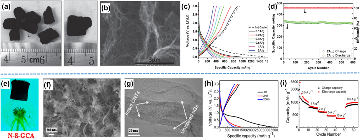
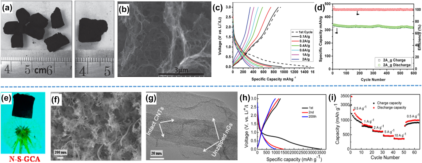
Constructing 3D carbon frameworks which consist of nanocarbon subunits with hierarchical structure is also an important method to avoid stacking problem and enhance electrochemical performance. Recently, Zuo et al.Reference Zuo, Kim, Kholmanov, Li, Chou and Li39 fabricated a 3D interconnected graphene framework (HPGF) electrode with large-scale continuity in an environment-friendly method [Fig. 3(a)]. The 3D hierarchical structure consisted of graphene nanosheets, with macropores and in-plane nanopores throughout the carbon framework [Fig. 3(b)]. The BET surface area of HPGF was 661 m2/g, and the pore size concentrated at ∼3 nm. At a small current density (100 mA/g), the first charge and discharge gravimetric capacities are 932 and 1519 mA h/g, respectively, with an initial reversible Coulombic efficiency of 61.3% [Fig. 3(c)]. After 600 cycles at 2 A/g, HPGF still can deliver a reversible capacity of 318 mA h/g, with the corresponding capacity retention of 93.5% [Fig. 3(d)]. Yi et al.Reference Chen, Jin, Wen, Lan, Yu, Sun and Yi40 used a facile and scalable strategy to construct highly integrated, intrinsically coupled, N,S-doped 3D graphene nanosheets trapped within carbon nanotubes (nGs@CNTs) through a modified counterion intercalation. The obtained nGs@CNTs framework (N–S-GCA) had a low gravimetric density [Fig. 3(e)], an interconnected porous structure, [Fig. 3(f)] and a high surface area of 621 m2/g and high electrical conductivity (approximately 105 S/m). Carbon nanotube can effectively prevent graphene nanosheets from stacking, and porous structure facilitated rapid diffusion of lithium-ions [Fig. 3(g)]. The first discharge capacity of N–S-GCA was 3471 mA h/g at 2 A/g, and the ICE was cycle was relatively low (36%) [Fig. 3(h)]. When the current density increased to 10 A/g, the N–S-GCA still can exhibit a high discharge capacity of 364 mA h/g [Fig. 3(i)].
(a) Digital photograph and (b) SEM image of HPGFsReference Zuo, Kim, Kholmanov, Li, Chou and Li39; (c) Charge–discharge curves of HPGFs and (d) Cycle performance of HPGFs at 2 A/g.Reference Zuo, Kim, Kholmanov, Li, Chou and Li39 (e) Digital photograph,Reference Chen, Jin, Wen, Lan, Yu, Sun and Yi40 (f) SEM image and (g) TEM image of N–S-GCAReference Chen, Jin, Wen, Lan, Yu, Sun and Yi40; (h) Charge–discharge curves of N–S-GCA at 2 A/g, and (i) Rate capabilities of N–S-GCA.Reference Chen, Jin, Wen, Lan, Yu, Sun and Yi40
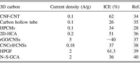
The major drawback of these hierarchically structured nanocarbon anode was their low ICE (most of which lower than 50%), which means a huge irreversible capacity loss in the first cycle. The low ICE can be attributed to the formation of SEI layer and the decomposition of electrolyte on the surface of nanocarbon. The ICE of above mentioned work was summarized in Table I. Sustained efforts should be made to improve the ICE of these nanocarbon anodes, for example, modifying chemical properties of the HSCN surface. Another challenge is that most of nanocarbons with a hierarchical structure show no obvious platform in the charge–discharge profiles. Most discharge capacity and charge capacity of nanocarbons were delivered at high voltage (>0.5 V). In addition, because of the porous structure, HSCNs always possess low tap density (which is obtained by vibrating powder in a container, and record the readings when the volume of powder does not reduce anymore, finally, divide the weight of powder by its volume), which would damage the volumetric energy density of LIBs. Therefore, developing HSCNs with high tap density has a significant meaning for improving energy density of LIBs, and this will be a hot and important research topic in the future.
Summary of ICE for different HSCNs.

III. HIERARCHICALLY STRUCTURED NANOCARBONS FOR SIBS
The further application of LIBs in large-scale energy storage systems is limited by the shortage of lithium resources. Sodium ions has similar electrochemical properties with lithium ions, while its resources is much richer on the earth than that of lithium.Reference Xu, Wang, Wickramaratne, Jaroniec, Dou and Dai41 Therefore, sodium ion batteries (SIBs) are expected to be a low cost alternative to lithium ion batteries (LIBs). However, it is difficult for most LIB anodes to storage sodium ions because of its large radius (0.098 nm, 55% larger than that of Li+), especially for graphite, whose interlayer distance is too narrow to accommodate sodium ions intercalation.Reference Yan, Yin, Guo and Wan42 Therefore, it is very important to develop advanced electrode materials with better sodium-ion storage performance for SIB anodes. In recent years, carbon nanomaterials have been proved to be promising candidate as anode for SIBs due to their considerable reversible capacity and low operating potential.Reference Ding, Wang, Li, Kohandehghan, Cui, Xu, Zahiri, Tan, Lotfabad, Olsen and Mitlin43 Hierarchical structured carbon nanomaterials have been applied in this field.
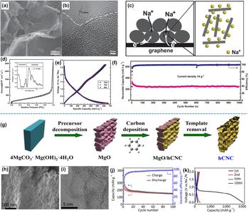
Wan et al.Reference Yan, Yin, Guo and Wan42 built a porous carbon-graphene-porous carbon sandwich-like hierarchical structure (G@HPC) via a facile ionothermal process [Figs. 4(a) and 4(b)]. Porous carbon on both sides of graphene facilitates Na+ diffusion within bulk electrode material, while the graphene sandwiched by porous carbon guarantees fast electron transport [Fig. 4(c)]. G@HPC composite exhibited broad pore size distributions in the micro- and mesoranges with a specific surface area of 825.9 m2/g [Fig. 4(d)]. The hierarchical structure would offer more favorable transport routes for the Na+, while the large surface area provides Na+ with more adsorption sites. When G@HPC was applied as anode materials of SIBS, there was no obvious voltage platform in the charge–discharge profiles [Fig. 4(e)]. It delivered a stable capacity of 364 mA h/g after 1000 cycles at 1 A/g. Hu et al.Reference Lyu, Yang, Xu, Zhao, Lai, Jiang, Wu, Li, Wang and Hu44 synthesized a hierarchical carbon nanosheet by using MgO nanosheets derived from 4MgCO3·Mg(OH)2·5H2O as template [Fig. 4(g)]. The carbon nanosheets consisted of interconnected hierarchical carbon nanocages (hCNCs) [Fig. 4(h)], and the size of the cages was ∼5 nm [Fig. 4(i)]. The hCNCs had a large surface area of 1051 m2/g, with coexisting micro, meso, and macropores. When applied as anode for SIBs, the hCNCs exhibited a capacity of 150 mA h/g after 100 cycles at 0.1 A/g [Fig. 4(j)]. Similar to other nanocarbon anodes for SIBs, hCNCs exhibited a quit low ICE, and had no obvious voltage platform in the charge–discharge curves after the first cycle [Fig. 4(k)].
(a) SEM image and (b) TEM image of G@HPCReference Yan, Yin, Guo and Wan42; (c) Schematic illustration of Na storage in the G@HPCReference Yan, Yin, Guo and Wan42; (d) Nitrogen adsorption/desorption isotherms of SPC@G nanocomposite; (e) Voltage profile at 50 mA/g; and (f) Long-cycle performance at 1A/g of G@HPC.Reference Yan, Yin, Guo and Wan42 (g) Schematic diagram for the formation of hCNC via in situ MgO template methodReference Lyu, Yang, Xu, Zhao, Lai, Jiang, Wu, Li, Wang and Hu44; (h) SEM image and (i) TEM image of hCNCReference Lyu, Yang, Xu, Zhao, Lai, Jiang, Wu, Li, Wang and Hu44; (j) Cycle capability and coulombic efficiency and (k) the corresponding voltage profiles at low rate of 0.1 A/g.Reference Lyu, Yang, Xu, Zhao, Lai, Jiang, Wu, Li, Wang and Hu44

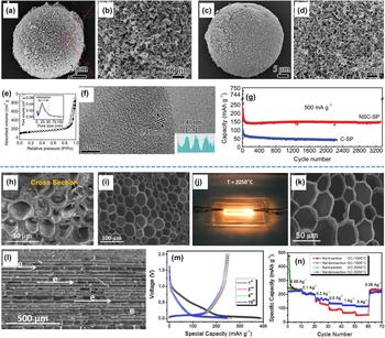
The sodium ion storage mechanisms of hard carbons which have nanostructures obey a “house of cards” model. Expanded interlayer distances of nanocarbons can bring positive effects on facilitating Na+ insertion in hard carbon and therefore improve the rate performance of SIBs. Zhang et al.Reference Xu, Chen, Xie, Zhang, Miao, Cai, Huang and Zhang45 synthesized a N/S dual-doped carbon nanospheres (NSC-SP) with an expanded interlayer distance by pyrolyzing cellulose/polyaniline (PANI) (9:1 by weight) microspheres which containing dodecyl benzene sulfonic acid (DBSA) dopant. The composite of cellulose/PANI and DBSA had a hierarchical spherical structure which consisted of numerous nanofibers [Figs. 5(a) and 5(b)]. After carbonization, the hierarchical spherical-like structure was remained perfectly [Figs. 5(c) and 5(d)]. NSC-SP had a porous structure with pore size lower than 50 nm [Fig. 5(e)]. The interlayer distance of NSC-SP was 0.41 nm, much higher than that of graphite [Fig. 5(f)]. The expanded interlayer space can be attributed to the hoping of heteroatoms, especially S doping. When applied as anode for SIBs, the NSC-SP delivered a stable capacity of 150 mA h/g after 3400 cycles at a current density of 500 mA/g [Fig. 5(g)].
(a) and (b) SEM images of cellulose-PANI-DBSA compositeReference Xu, Chen, Xie, Zhang, Miao, Cai, Huang and Zhang45; (c) and (d) SEM images of NSC-SPReference Xu, Chen, Xie, Zhang, Miao, Cai, Huang and Zhang45; (e) Nitrogen absorption/desorption isotherm (inset: pore size distribution) and (f) TEM image (inset: corresponding intensity profile for the line scan across the lattice fringes) of NSC-SPReference Xu, Chen, Xie, Zhang, Miao, Cai, Huang and Zhang45; (g) Cycle performance of NSC-SP at a current density of 500 mA/g.Reference Xu, Chen, Xie, Zhang, Miao, Cai, Huang and Zhang45 (h) SEM image of switchgrass stemReference Zhang, Yao, Wan, Henderson, Zhang and Hu46; (i) SEM image of GC-1000Reference Zhang, Yao, Wan, Henderson, Zhang and Hu46; (j) Digital photograph of switchgrass derived carbon under Joule heatingReference Zhang, Yao, Wan, Henderson, Zhang and Hu46; (k) SEM image of cross section from GC-2050Reference Zhang, Yao, Wan, Henderson, Zhang and Hu46; (l) SEM image of longitudinal section from GC-2050Reference Zhang, Yao, Wan, Henderson, Zhang and Hu46; (m) Voltage profiles at GC-2050 at 50 mA/g and (n) Rate performance of GC-1000 and GC-2050.Reference Zhang, Yao, Wan, Henderson, Zhang and Hu46

On the one hand, large surface area provides abundant active sites for sodium-ion storage. On the other hand, a low ICE may occur because of electrolyte decomposition on the surface of nanocarbons. Designing carbon nanomaterials with low surface can be useful to improve ICE of SIBs. Hu et al.Reference Zhang, Yao, Wan, Henderson, Zhang and Hu46 developed a hierarchical carbon architecture with low surface area by carbonizing switchgrass at a very high temperature. The switchgrass stems had a hierarchical structure [Fig. 5(h)], and after carbonization at 1000 °C, the obtained carbon (GC-1000) maintained the hierarchical structure of pristine switchgrass stems [Fig. 5(i)]. The GC-1000 was further heated at 2050 °C with a Joule heating process under Ar [Fig. 5(j)], and finally a 3D hierarchical structured carbon (GC-2050) with partially graphitization nature can be obtained. The 3D hierarchical GC-2050 was composed of interconnected carbon nanosheets with a thickness of ∼200 nm [Fig. 5(k)]. Parallel channel structures which benefit ion diffusion can be observed in the carbon framework of GC-2050 [Fig. 5(l)]. The BET surface area of GC-2050 was only 23 m2/g. As anode for SIBs, GC-2050 delivered an ICE of 64%, higher than that of GC-1000 (50 mA/g) [Fig. 5(m)]. In addition, GC-2050 had an obvious voltage platform under 0.1 V in the discharge processes. After 800 cycles, a stable capacity of 200 mA h/g was retained with a CE nearly 100% [Fig. 5(n)].
Although many HSCNs have been designed and synthesized for SIBs in recent years, some challenges still were not well solved. Similar with that of LIBs, the ICE of SIBs was too low to satisfy the practical needs (some were even lower than 30%). The low ICE, which resulted from the formation of SEI and decomposition of the electrolyte in the first cycle, would damage the electrochemical performance and increase the costs of SIBs. Chemically surface modification and decreased specific surface area of HSCNs may have a positive effect on improve the ICE. In addition, synthesizing HSCNs with extended interlayer distance can facilitate the sodium ion diffusion and improve electrochemical performance of SIBs. Furthermore, an increased graphitization degree may make contribute to a lower discharge platform, which has practical significance for SIBs.
IV. HIERARCHICALLY STRUCTURED NANOCARBONS FOR SUPERCAPACITORS
Electrochemical supercapacitors have attracted increasing attention due to its high power density. Carbon nanomaterials are the most classical electrode materials for electrochemical double layer capacitors (EDLCs).Reference Liu, Zhu, Kou, Worsley, Qian, Condes, Duoss, Spadaccini and Li47–Reference Huang, Liu, Song, Li and Liu52 The capacity (C) of EDLCs at each electrode interface can be given by
 $$C = {{\varepsilon A} \over {4\pi d}}\quad ,$$
where ε is the dielectric constant of the electrical double-layer region, A the surface area of the electrode and d is the thickness of the electrical double layer.Reference Pandolfo and Hollenkamp53 It can be concluded that a higher A leaded to higher C. From this point of view, building hierarchical structure and preventing carbon nanomaterials from stacking have a significant meaning on improving electrochemical capacity of EDLCs.
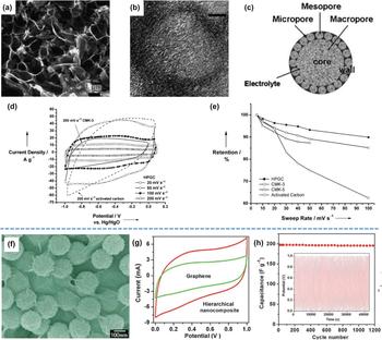
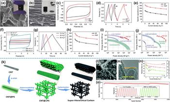
Cheng et al.Reference Wang, Li, Liu, Lu and Cheng54 developed a hierarchically structured graphitic carbon with porous network (HPGC) for electrode materials of EDLCs. The HPGC was composed of graphitic carbon nanosheets, and the adjacent nanosheets formed interconnected pores [Figs. 6(a) and 6(b)]. The 3D hierarchical porous texture of HPGC combined macroporous cores to reduce the diffusion distances, mesoporous walls can provide low-resistant pathways for ions, and the micropores to improve the electric-double-layer capacitance. This hierarchical architecture composed of macroporous cores and mesoporous walls was self-supported and able to overcome nanoparticle aggregation [Fig. 6(c)]. The graphitic structure can increase the electric conductivity of HPGC. The cyclic voltammetry (CV) profiles of HPGC retain a quasi-rectangular shape at sweep rates ranged between 20 and 200 mV/s [Fig. 6(d)] in an aqueous solution. Based on the 3D hierarchical structure, HPGC delivered much better capacitance retention compared with CMK-3 (rod like ordered mesoporous carbon), CMK-5 (tubular-like ordered mesoporous carbon) and activated carbon [Fig. 6(e)]. Li et al.Reference Guo and Li55 synthesized a hybrid materials of carbon nanospheres and graphene with assistance of poly(diallyldimethylammoniumchloride) (PDDA). 0D carbon nanospheres act as nano-spacers to separate 2D graphene sheets [Fig. 6(f)]. This composite show a rectangular-like CV curve [Fig. 6(g)], and its specific capacity was higher than that of graphene. In addition, it delivered a stable capacity of ∼200 F/g after 1200 cycles [electrolyte: 6 M KOH in aqueous solution, Fig. 6(h)].
(a) SEM image of the macroporous cores of the HPGC materialReference Wang, Li, Liu, Lu and Cheng54; (b) TEM image of the localized graphitic mesopore wallsReference Wang, Li, Liu, Lu and Cheng54; (c) Schematic representation of the 3D hierarchical porous textureReference Wang, Li, Liu, Lu and Cheng54; (d) CV curves in an alkaline electrolyte (6 M KOH) within the potential range: 1.0–0.1 V of HPGC and (e) Capacitance retention ratio as a function of the potential sweep rates of HPGC.Reference Wang, Li, Liu, Lu and Cheng54 (f) SEM image of the graphene-carbon nanosphere compositeReference Guo and Li55; (g) CV curves and (h) cyclic stability of the graphene-carbon nanosphere composite, the inset shows the first 300 charge–discharge cycles.Reference Guo and Li55

Developing high energy density electrode materials is crucial to bridge the gap between traditional supercapacitors and batteries. Duan et al.Reference Xu, Lin, Zhong, Huang, Weiss, Huang and Duan56 developed a 3D holey graphene framework (HGF) with a porous structure as high performance binder-free supercapacitor electrodes. The graphene hydrogels was composed of self-assembled graphene nanosheets with interconnected 3D macroporous network [Fig. 7(a)]. After being compressed, HGF was used as electrode materials of EDLCs [Fig. 7(b)]. It was worth noting that the BET surface area of compressed HGF (810 m2/g) was closed to that of HGF (830 m2/g), which means the compressing process did not sacrifice the surface area of this nanocarbon. When tested in 6 M KOH, it delivered a rectangular CV curve [Fig. 7(c)], and the capacity was higher than that of graphene framework (GF). In addition, HGF shew small voltage drop (IR drop) of 0.12 V [Fig. 7(d)]. The HGF electrodes exhibited an ultrahigh specific capacitance of 310 F/g at a current density of 1 A/g [Fig. 7(e)]. When tested in EMIMBF4/AN (organic condition), it also delivered a rectangular CV curve [Fig. 7(f)] and a very small IR drop [Fig. 7(g)]. The HGF electrodes exhibited an ultrahigh specific capacitance of 298 F/g at a current density of 1 A/g, which can compare with energy density in aqueous solution [Fig. 7(h)]. Interestingly, HGF exhibited higher gravimetric and volumetric energy densities of 35 W h/kg and 49 W h/L [Figs. 7(i) and 7(j)]. The high energy density even approached that of lead acid batteries. Wu et al.Reference Liang, Chen, Zhuang, Liu, Fu, Zhang, Wu and Matyjaszewski57 developed a novel super-hierarchical carbons (SHCs) with a unique carbonaceous hybrid nanotube-interconnected porous network structure by utilizing well-defined carbon nanotube@polystyrene (CNT@PS) bottlebrushes as building blocks. To prepare the SHCs, firstly, PS chains was grafted from the surface of CNT via surface-initiated atom transfer radical polymerization (SI-ATRP), and then CNT@PS was treated with a facile hypercrosslinking reaction to form a crosslinked and porous network of CNT@xPS, fand finally SHCs was obtained by directing heat treat of CNT@xPS [Fig. 7(k)]. The hierarchical structure of CNT@xPS was formed in the hypercrosslinking process, and after the carbonization process, the super-hierarchical carbon in which the interconnected porous carbon network (amorphous) coated on the outer surface in CNT (graphitic) was achieved [Figs. 7(l) and 7(m)]. The BET surface area of SHCs was 635 m2/g. Based on the advanced structure, SHCs delivered high area specific and excellent capacity retention at high current density [Fig. 7(n)]. When at 1 A/g, after 10,000 cycles, it still remained about 100% of the initial capacitance [Fig. 7(o)].
(a) SEM image of interior microstructures of HGFs (Scale bar, 1 μm), and the inset: a photograph showing a free-standing HGFReference Xu, Lin, Zhong, Huang, Weiss, Huang and Duan56; (b) SEM image of the compressed HGF film. Scale bar, 1 μm, and the inset: a photograph showing HGFs before and after mechanical compression and the flexibility of the compressed HGF filmReference Xu, Lin, Zhong, Huang, Weiss, Huang and Duan56; (c) CV curves of HGF at a high scan rate of 1000 mV/s and (d) Galvanostatic charge/discharge curves of HGF at a high current density of 100 A/g in 6 M KOH, and (e) Specific capacitances versus different current densities for HGF-EC in 6 M KOHReference Xu, Lin, Zhong, Huang, Weiss, Huang and Duan56; (f) CV curves, (g) Galvanostatic charge/discharge curves in EMIMBF4/AN, and (h) Specific capacitances of HGF electrodes versus different current densities in EMIMBF4/ANReference Xu, Lin, Zhong, Huang, Weiss, Huang and Duan56; (i) Ragone plots of gravimetric energy density versus gravimetric power density for HGF and (j) Ragone plots of volumetric energy density versus volumetric power density for HGF in comparison of other type energy storage devices.Reference Xu, Lin, Zhong, Huang, Weiss, Huang and Duan56 (k) Schematic illustration of the preparation of super-hierarchical carbons from well-defined heterogeneous core–shell CNT@PS bottlebrushesReference Liang, Chen, Zhuang, Liu, Fu, Zhang, Wu and Matyjaszewski57; (l) SEM images and (m) TEM images of SHCReference Liang, Chen, Zhuang, Liu, Fu, Zhang, Wu and Matyjaszewski57; (n) capacitance retention ratios and specific capacitances per surface area for SHC (red) and activated carbon (green)Reference Liang, Chen, Zhuang, Liu, Fu, Zhang, Wu and Matyjaszewski57; (o) Long-term cycling stability over 10,000 cycles for SHC at a current density of 1 A/g; the inset shows the curves for the first and last ten cycles.Reference Liang, Chen, Zhuang, Liu, Fu, Zhang, Wu and Matyjaszewski57

The hierarchical structure of HSCNs have improved electrochemical performance of EDLCs; however, the low tap density of HSCNs, which resulted from the large surface area and porous structure, would damage volume energy density of supercapacitors. Developing HSCNs with high tap density is valuable for improve comprehensive performance of supercapacitors. In addition, increasing wettability of HSCNs by means of heteroatom doping and other method, will be also helpful to achieve an enhanced capacity and improved rate capability because better wettability can guarantee better accesses of electrodes to electrolyte. This will be a promising research topic which valuable to be investigated in the future.
V. HIERARCHICALLY STRUCTURED NANOCARBONS FOR LI–S BATTERIES
Lithium–sulfur (Li–S) batteries have attracted enormous research interest due to its theoretical capacity (1672 mA h/g) and energy density (2600 W h/kg).Reference Yuan, Peng, Huang, Liu, Wang, Cheng and Zhang58,Reference Deng, Hu, Chen, Zhang, Tang, Liu, Fan and Xiao59 Therefore it has been regard as important power sources for future electric vehicles. However, the practical application of pure sulfur cathodes is hindered by low intrinsic electric conductivity, huge volume expansion during lithiation processes and shuttle effects of lithium polysulfides.Reference Zheng, Guo, Pei, Zhang, Chen, Fang, Wang and Zheng60–Reference Xu, Ding, Nie, Shen, Dou and Zhang67 Porous nanocarbons have been investigated as hosting materials for Li–S battery cathode, because carbon matrix enhances conductivity of sulfur, alleviate volume change during cycling and restrict the shuttling of the polysulfides.
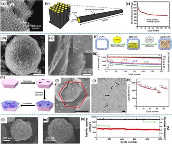
In recent years, many hierarchical carbon architectures with porous structure have been developed to host sulfur cathode. The pores can act as a reservoir to storage sulfur and enable electrochemical reaction occur inside. Cui et al.Reference Zheng, Yang, Cha, Hong and Cui68 synthesized a hollow carbon nanofiber array by using AAO as templates, then the hollow carbon nanofiber was used as sulfur host for Li–S batteries [Fig. 8(a)]. The hollow carbon nanofiber had a length of ∼60 μm and a diameter of ∼200 nm. Sulfur powder was coated on the inner surface of hollow carbon nanofibers [Fig. 8(b)]. The high length/diameter ratio made it possible to trap polysulfides, and hollow structure also accelerated diffusion speed of lithium ions. With a sulfur loading of 75% and 0.1 M LiNO3 additive in the electrolyte, the hollow carbon fibers delivered an initial capacity of 1560 mA h/g, which approached the theoretical capacity of sulfur (current density: 0.5 C). After 150 cycles, it stilled delivered a capacity of ∼700 mA h/g. Hu et al.Reference Lyu, Xu, Yang, Che, Feng, Zhao, Li, Wu, Wang and Hu69 also applied their hCNC as cathode host for Li–S batteries. The small-sized carbon nanocages interconnected and formed carbon nanosheets, and these carbon nanosheets further assembled to spherical-like carbon nanoparticles [Figs. 8(d) and 8(e)]. The pore volume is 4.178 cm3/g, which was appropriate to host sulfur cathode. Especially, the inner volume of the small carbon nanocages can act as buffering matrix for volume expansion of sulfur during discharge process, and restrict shuttle effect of polysulfides [Fig. 8(f)]. When highly loaded with sulfur at 79.8%, hCNC delivered a specific capacity of 419 mA h/g after 100 cycles at 0.5 A/g [Fig. 8(g)].
(a) Hollow carbon nanofiber encapsulated sulfur after etching away AAO templateReference Zheng, Yang, Cha, Hong and Cui68; (b) The design principle showing the high aspect ratio of the hollow carbon nanofiber for effective trapping of polysulfidesReference Zheng, Yang, Cha, Hong and Cui68; (c) Capacities of the carbon nanofiber-encapsulated sulfur electrode in electrolyte with LiNO3 additive at C/5.Reference Zheng, Yang, Cha, Hong and Cui68 (d) and (e) SEM images of hCNC, and the inset of (c) TEM image of hCNCReference Lyu, Xu, Yang, Che, Feng, Zhao, Li, Wu, Wang and Hu69; (f) A schematic diagram of constructing S@hCNC composite via melt-diffusion and subsequent lithiation and high-rate capabilityReference Lyu, Xu, Yang, Che, Feng, Zhao, Li, Wu, Wang and Hu69; (g) long cyclability and Coulombic efficiency of hCNC at different high current densities (sulfur loading: 79.8%).Reference Lyu, Xu, Yang, Che, Feng, Zhao, Li, Wu, Wang and Hu69 (h) Scheme for the synthesis of unstacked DTGReference Zhao, Zhang, Huang, Tian, Nie, Peng and Wei29; (i) and (j) TEM images of DTG at different magnifications, and (k) rate performance of the DTG/S cathode.Reference Zhao, Zhang, Huang, Tian, Nie, Peng and Wei29 (l) SEM image of PACP/PEO-b-PS composite nanospheresReference Tang, Liu, Lu, Lin, Zheng, Liu, Wu and Fu70; (m) SEM image of PCNS and (n) the specific capacity (red) and coulombic efficiency (black) over 1000 cycles at 2 C for PCNS/S cathodes.Reference Tang, Liu, Lu, Lin, Zheng, Liu, Wu and Fu70

Zhang et al.Reference Zhao, Zhang, Huang, Tian, Nie, Peng and Wei29 constructed an intrinsically unstacked double-layer templated graphene via template-directed chemical vapor deposition. To be specific, Mg–Al LDO derived from Mg–Al LDH was used as template, and graphene layer were deposited are the surface of side surfaces of LDO plates during CVD process. The as-obtained graphene was composed of two unstacked graphene layers separated by a large amount of mesosized protuberances, and the formation of graphene protuberances was attributed to the graphene being cast on the inner surface of the mesopores of the LDO templates [Figs. 8(h)–8(j)]. The protuberances can serve as nano-spacers to prevent graphene layers from stacking, thus maintain the high surface area of DTG. As a result, DTG shown a BET surface area of 1628 m2/g and a pore volume of 2 cm3/g. The hierarchical structure of DTG was used as cathode host of Li–S batteries. When tested at a high discharge rate of 10 C, the DTG–S composite achieved a high reversible capacity of 713 mA h/g, and it also exhibited excellent rate performance [Fig. 8(k)]. The superior electrochemical performance can be attributed to the unique structure of DTG. Wu et al.Reference Tang, Liu, Lu, Lin, Zheng, Liu, Wu and Fu70 synthesized a novel N-doped carbon nanospheres (PCNSs) based upon the copolymerization-induced self-assembly of aniline/pyrrole co-monomers and polyoxyethylene-b-polystyrene (PEO-b-PS). The aniline/pyrrole co-monomers strongly interacted with PEO-b-PS micelles, and their copolymerization [poly(aniline-co-pyrrole), PACP] organizes the PEO-b-PS micelles together to form well-defined bayberry-like nanospheres [Fig. 8(l)]. After the followed carbonization process, the sphere-like structure was maintained in N-doped PCNSs, in which carbon nanoparticles decorated on the surface on carbon nanospheres [Fig. 8(m)]. The direct carbonization of PACP/PEO-b-PS composite not only generated large mesopores resulting from decomposition of PS segments of the micelles, but also leaded to ultrahigh surface areas because of introduction of numerous micropores into the resultant carbon framework. The BET surface area of as-obtained PCNSs was 2520 m2/g and the pore volume was 1.43 cm3/g. Such porous structure enabled it can be superior cathode hosts for Li–S batteries. When tested at 2 C, the PCNSs-S cathode exhibited an initial discharge capacity of 856 mA h/g, and a high reversible capacity of 715 mA h/g was retained after 1000 cycles [Fig. 8(n)].
The HSCNs hosts have increased electric conductivity and alleviated volume change of sulfur cathodes; however, the shuttle effects of lithium polysulfides have not been addressed well, and capacity fading still is a big problem of Li–S batteries. Designing hierarchical pores with more rationally distributed size and constructing closed pores may alleviate the shuttle effect. Moreover, heteroatom doping, especially N and S doping, can have a positive effect on resting polysulfides. Rational designed pore structure and heteroatom doping may have a synergistic strategy to address the shuttle effect problem. Apart from this, mass loading of sulfur on the HSCN was usually lower than 2 mg/cm2, which cannot afford an increasing demand on energy density. Constructing HSCNs with high sulfur loading can make contribute to improve energy density of Li–S batteries.
VI. CONCLUSIONS AND PROSPECTIVES
We have summarized recent progress in hierarchical structure design of carbon nanomaterials and their applications in lithium/sodium-ion batteries, lithium–sulfur batteries and supercapacitors. In general, there are two approaches to construct the hierarchical structure. One is ‘top-down’ approach, i.e., fabricating a framework first and then preparing subunit nanocarbon on the framework. The other is ‘bottom-up’ approach, i.e., preparing nanocarbon subunits first and then integrating them into an integrated architecture. The hierarchical structure can effectively alleviate the aggregation problem of nanocarbon subunits, create smooth ion diffusion channels and thus promote full utilization of the active sites. The interconnected conductive framework benefits fast electron conduction and charge transfer. Meanwhile this framework also enables better structural stability than the individual nanocarbon subunit. Therefore, high-rate capability and cycling stability can be achieved. When designing HSCNs for LIBs, interconnected porous structure can shorten diffusion length of Li+ ions, and micropores as well as large surface area can provide abundant Li+ ion storage sites. Nevertheless, large surface also increases irreversible capacity loss in the first cycle. Therefore, moderate surface area and porous structure with abundant micropores are required when designing HSCNs as anode for LIBs. As for HSCNs for SIBs, moderate surface and interconnected structure are also required. However, because of the larger radius of Na+ ions, larger size pores, such as mesopores, will be better for Na+ ion storage. When designing HSCNs for supercapacitors, achieving huge surface area is the most important aspects, because there is a positive correlation between capacity of supercapacitors and the surface area. As for HSCNs for Li–S batteries, a large pore volume has a great meaning, because this means more space for sulfur hosting. In addition, constructing hierarchical porous structure in HSCNs which means the co-existence of micropores, mesopores and macropores can have positive effects on Li–S battery performance.
Despite the structure and performance merits of HSCNs, their wide applications in energy storage fields are still hindered by several factors. First, the synthesis processes of HSCNs are still complex and cost-expensive. Developing facile synthesis procedures at a large scale would be one of the future directions. Besides, there are several challenges for various energy storage technologies need to be addressed. For lithium/sodium-ion batteries, low ICE is a big obstacle. Surface modification of HSCNs could promote stable SEI formation, and optimize the value of surface area may decrease irreversible capacity loss of HSCNs during the first cycle. For supercapacitors, the most important thing is to increase the tap density of HSCNs to make HSCNs materials compatible to current industrial slurry-coating process and also to increase the volumetric energy density. Constructing graphene aerogel may a promising approach to achieve this goal. In addition, introducing heteroatom dopants, especially N doping, can increase wettability of HSNCs and thus improve the electrochemical performance. As for lithium–sulfur batteries, building hierarchical carbon nanohosts to prevent sulfur dissolution can be of great significance. Further increasing the pore volume can increase the sulfur loading ability of HSCNs, and optimizing the ratio of micropores, mesopores and macropores have significant meanings for promoting electrochemical reaction of sulfur cathode. Functional group modification on the framework of HSCNs can also effectively restrict the shuttle effects of polysulfide. With continuous research efforts in hierarchical architecture design of carbon nanomaterials and electrochemical technique optimization, more and more advanced HSCNs materials for high-performance energy storage are expected to be achieved.
ACKNOWLEDGMENTS
This work was supported by the National Key Basic Research Program of China (2014CB932400), the National Natural Science Foundation of China (51672156 and 51232005), the Guangdong special support program (2015TQ01N401), and the Shenzhen Technical Plan Project (KQJSCX20160226191136 and JCYJ20170412170706047).