I. INTRODUCTION
Bulk metallic glasses (BMGs) are very promising materials for the production of microdevices. They exhibit high strengths and hardnesses and are therefore regarded as attractive structural materials in microelectromechanical systems.Reference Greer and Ma1, Reference Inoue and Nishiyama2 Their outstanding mechanical properties are important for the applications like micromouldsReference Kumar, Tang and Schroers3 or tools for microembossing techniques.Reference Henann, Srivastava, Taylor, Hale, Hardt and Anand4 Soft magnetic glassy alloys based on Fe or Co are, furthermore, the appropriate materials for micrometer-sized yokes in positioning systemsReference Inoue and Nishiyama2 or magnetic cores.Reference Roth, Stoica, Degmová, Gaitzsch, Eckert and Schultz5
However, forming microparts from BMGs is still challenging. In general, thermomechanical forming is a promising technique for shaping them.Reference Saotome, Imai, Shioda, Shimizu, Zhang and Inoue6–Reference Chen, Zhang, Zhang and Chen11 Using this method, surface patterningReference Saotome, Imai, Shioda, Shimizu, Zhang and Inoue6, Reference Kündig, Cucinelli, Uggowitzer and Dommann7 and the production of micropartsReference Schroers8, Reference Nishiyama and Inoue9 were demonstrated. Nevertheless, this technique exhibits some disadvantages.Reference Kündig, Cucinelli, Uggowitzer and Dommann7, Reference Schroers8, Reference Schroers, Nguyen, O’Keeffe and Desai10, Reference Chen, Zhang, Zhang and Chen11 The processing is only possible for glassy alloys exhibiting a wide undercooled liquid region at low temperatures. For thermomechanical processing, a strict temperature and atmosphere control is needed to avoid crystallization and oxidation. Therefore, a shaping technique operating at room temperature might open new possibilities for the utilization of glassy alloys.
For crystalline metallic materials, different electrochemical methods operating at low temperatures were developed in the past.Reference Landolt, Chauvy and Zinger12 In the electrochemical machining process, the shape of the cathode (tool electrode) is reproduced on the anode (work piece) by a diffusion-limited high-rate anodic dissolution. The current densities in this process can exceed 100 A/cm2, and electrolyte flow rates in the electrode gap of several meters per second are used.Reference Landolt, Chauvy and Zinger12 High machining rates of up to 1 mm/min are achieved. However, the accuracy is limited to about 0.1 mm.Reference Bhattacharyya, Munda and Malapati13 A more recent development is the pulsed electrochemical micromachining (ECMM) allowing a submicrometer precision.Reference Bhattacharyya, Munda and Malapati13 A microsized tool electrode is brought in close distance to the work piece surface. When applying ultrashort voltage pulses, the rate determining step of the anodic dissolution is the charging of the electrochemical double layer (DL). For small distances between the work piece and directly under the tool electrode, the resistance through the electrolyte is small and the DL is charged sufficiently for a significant anodic dissolution rate. At larger distances laterally from the tool electrode, the resistance through the electrolyte is high and the DL is not charged sufficiently for a significant dissolution rate. Therefore, by applying short voltage pulses, a highly localized material removal is possible.Reference Schuster, Kirchner, Allongue and Ertl14–Reference Maurer, Mallett, Hudson, Fick, Moffat and Shaw16 The ECMM technique was successfully used for machining crystalline materials such as Cu, Ni, and stainless steel in high precision.Reference Schuster, Kirchner, Allongue and Ertl14–Reference Maurer, Mallett, Hudson, Fick, Moffat and Shaw16 It has also been demonstrated that high aspect ratios of the machined structures and complex shapes can be achieved.Reference Kock, Kirchner and Schuster17, Reference Sen and Shan18 However, the impact of the passive layer of spontaneously passive alloys and the high metalloid content of metal–metalloid type BMGs (as used in this study) have been scarcely investigated. Maurer et al.Reference Maurer, Mallett, Hudson, Fick, Moffat and Shaw16 demonstrated that the micromachining process exploiting the transpassive dissolution is possible for the nickel-based superalloy “Hastelloy B-2.” Koza et al.Reference Koza, Sueptitz, Uhlemann, Schultz and Gebert19 demonstrated that the machining of a Zr-based metal–metal type BMG is in principle possible but only structures with irregular shapes were obtained.
For our study, we chose the alloy Fe65.5Cr4Mo4Ga4P12C5B5.5,Reference Stoica, Degmová, Roth, Eckert, Grahl, Schultz, Yavari, Kvick and Heunen20 which can be obtained by casting to a maximum amorphous sample diameter of 3 mm and which exhibits a strength of 2.84 GPa and an elongation to failure of 1.91% in compression.Reference Stoica, Eckert, Roth, Zhang, Schultz and Wang21 Furthermore, this alloy shows a coercivity of less than 10 A/m and a saturation polarization of 0.82 TReference Stoica, Eckert, Roth, Zhang, Schultz and Wang21 making it an interesting candidate for soft magnetic materials in microelectromechanical applications. A high corrosion resistance in media not containing halide ions promises a high chemical stability including severe conditions such as concentrated acid solutions. The glass transition temperature is 745 K, and an undercooled liquid region is limited to 61 KReference Stoica, Degmová, Roth, Eckert, Grahl, Schultz, Yavari, Kvick and Heunen20 making thermoplastic forming challenging.
The aim of the present study was to demonstrate the possibility of surface structuring of a Fe-based BMG with a high metalloid content by exploiting the transpassive dissolution. It is shown that the identification of a suitable electrolyte is crucial for the success of the ECMM process.
II. EXPERIMENTAL
Bulk glassy Fe65.5Cr4Mo4Ga4P12C5B5.5 rods of 1-mm diameter were cast and their microstructure was characterized as described elsewhere.Reference Stoica, Eckert, Roth, Yavari and Schultz22 Three-millimeter thick slices of these rods were embedded in epoxy resin and successively polished with SiC paper up to grit 4000 before using them as working electrode (WE).
Electrochemical characterization was carried out using a conventional three-electrode Teflon cell with a Pt mesh as counter electrode and a Hg/Hg2SO4/K2SO4(sat.)reference electrode [640 mV versus standard hydrogen electrode (SHE)]. All potentials given here are reported versus the SHE. In selected electrolytes, linear sweep voltammetry was performed with a potential scan rate of 2 mV/s.
For machining experiments, two types of microtool electrodes were used. Tungsten wires of 75-μm diameter were obtained from Goodfellow (Goodfellow Cambridge Ltd., Huntingdon, England). By electrochemical etching in 2 M NaOH electrolyte, as described in detail by Ju et al.,Reference Ju, Chen and Ge23 electrodes with diameters down to 10 μm were obtained. Furthermore, a Pt wire of 50-μm diameter was used. The microelectrodes were isolated with glass by inserting them into a glass capillary, which was then heated in a gas flame until the molten glass covered the metal apart from a small region approximately 400 μm in length.
The machining experiments were performed in the setup shown and explained in detail in Ref. Reference Stoica, Eckert, Roth, Zhang, Schultz and Wang21. However, in the present study, no bias potentials were applied to the work piece or tool electrode. For all machining experiments, a pulse–pause ratio of 1:10 was used. After the machining experiments, the WE surface was examined by means of optical microscopy. Surface depth profiles were recorded with a resolution of 1 point per 4 μm2using a white light profilometer (FRT MicroProf, FRT GmbH, Bergisch Gladbach, Germany). Linear structures were machined by raster scanning at a rate of 1 μm steps every 10 s. After the defined distances, the pulse potential was varied. Finally, the received structures were examined by scanning electron microscopy.
All experiments were conducted at least three times to ensure a high reproducibility.
III. RESULTS AND DISCUSSION
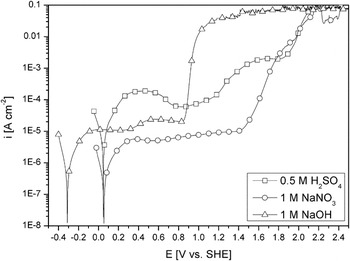
To characterize the polarization behavior of the glassy Fe65.5Cr4Mo4Ga4P12C5B5.5 alloy, potentiodynamic polarization curves were recorded in potential machining electrolytes. Typical curves recorded in acidic media (0.5 M H2SO4), alkaline media (1 M NaOH), and neutral media (1 M NaNO3) are shown in Fig. 1. In neutral and alkaline media, the alloy exhibits spontaneous passivity and a free corrosion current density i corr in the order of 1 μA/cm2. The passive current density i p is (5–10) μA/cm2 for the NaNO3 solution and (10–25) μA/cm2 for the NaOH solution, respectively. In H2SO4 solution, i corr is 9 μA/cm2, i.e., almost one order of magnitude higher than in the neutral and alkaline solution (∼1 μA/cm2). This comparatively high i corr and a logarithmic increase of the current density in the potential region of about 0.1–0.22 V indicate a charge transfer-controlled active dissolution mechanism. However, i corr as well as a maximum anodic current density of 180 μA/cm2 are much lower than those measured for pure iron in 0.5 M H2SO4 (i corr ∼300 μA/cm2 and maximum anodic current densities of about 200 mA/cm2) in a previous investigation.Reference Sueptitz, Koza, Uhlemann, Gebert and Schultz24 Thus, we suggest that in acidic media, under free corrosion conditions, the alloy is covered by a less protective passive layer than in alkaline or neutral solutions. The Tafel behavior might point to a selective dissolution mechanism but was not investigated in more detail. Beyond the current density maximum, the current density decreases to about 25 μA/cm2 at 0.8 V followed by an increase up to ∼70 μA/cm2 at 1.2 V. According to Pourbaix,Reference Pourbaix25 the anodic water decomposition starts at ∼1.2 V for the H2SO4 solution, at ∼0.85 V for the NaNO3 solution, and at 0.45 V for the NaOH solution. In case of the NaOH solution and the H2SO4 solution, an increase of the current density is indeed visible at these potentials but not in NaNO3 solution. However, in all electrolytes, the anodic water decomposition is strongly inhibited. It is only at high overpotentials, 0.4 V in NaOH solution or 0.65 V in H2SO4 solution, that a strong increase of the current density and visible gas evolution at the electrode occurs. Remarkably, the increase of the current density with potential is higher in the NaOH solution than in the NaNO3 solution and the H2SO4 solution. Only a polarization of 40 mV is needed to increase the current density by one order of magnitude in the NaOH solution compared to ∼130 mV for the other two. For comparison, values of (50–55) mV/dec. were recorded for pure Fe in H2SO4and NaOH solutions (not shown here). After the potentiodynamic polarization experiments, a significant material loss was visible at the specimen’s surfaces with the naked eye. Thus, a transpassive dissolution of the alloy occurs in all three electrolytes within the potential region of the potentiodynamic polarization tests, i.e., at potentials below 2.5 V (SHE).
Current density–potential curves of Fe65.5Cr4Mo4Ga4P12C5B5.5BMG recorded in selected electrolytes with a potential scan rate of 2 mV/s.

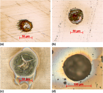
First machining attempts were conducted in the above-discussed electrolytes. Since tungsten dissolves in alkaline media, a 50-μm platinum tip was used. Fe, the main element of the glassy alloy, forms insoluble hydroxides in alkaline media.Reference Pourbaix25 Thus, on first view, this electrolyte appears not to be suitable for machining. However, due to the parallel oxygen evolution at the electrode surface, these hydroxides might be removed by the convection caused by the gas bubbles. The surface attack after applying pulses of 200 ns is shown in Fig. 2(a) for the 1 M NaOH solution, in Fig. 2(b) for the 1 M NaNO3 solution, and in Fig. 2(c) for the 0.5 M H2SO4 solution. The achieved pulse voltages measured between work piece and tool electrode were 6, 7, and 6.5 V, respectively. In 1 M NaOH solution [Fig. 2(a)], a localized corrosion attack occurred but with no significant material removal. The machined structure on the BMG surface exhibits about the same diameter as the used tool electrode. In the center region, the material remained shiny metallic; adjacent to this region, a rim region covered with a brown layer, which exhibits some cracks, is visible. This appearance did not change when the pulses were applied for several minutes.
Optical microscope images of machined structures on Fe65.5Cr4Mo4Ga4P12C5B5.5 BMG surface with a pulse length of 200 ns in (a) 1 M NaOH, (b) 1 M NaNO3, (c) 0.5 M H2SO4, and (d) 1 M HCl. (color online)

After applying 200 ns pulses in 1 M NaNO3 solution, limited localized material removal was observed as shown in Fig. 2(b). The appearance of the surface damage is not reproducible but the diameter of this zone always corresponds to the diameter of the tool electrode. A significant material removal allowing a feed rate of the tool electrode was not achieved. Voltage pulses of 6.5 V amplitude and 200-ns length applied between WE and tool electrode in 0.5 M H2SO4 solution resulted in the surface structure shown in Fig. 2(c). The affected surface area is larger than that obtained in NaOH solution or NaNO3 solution. In this area, a layer of dark gray corrosion products with cracks is visible. A possible formation mechanism of this structure is the film breaking mechanism, which was discussed by Streblow and LöchelReference Strehblow26, Reference Löchel and Strehblow27 for iron and nickel electrodes. The voltage pulse causes stress in the oxide layer, which leads to crack formation. However, since no ions promoting pitting corrosion are present in the solution, the electrode repassivates in the regions where the bare alloy surface was exposed to the electrolyte due to cracks in the oxide layer. Therefore, a significant material removal by active dissolution was not possible in this media.
Since halide ions must be expected to weaken the oxide layer, further machining attempts were conducted in solutions of 1 M HCl, 0.1 M HCl, 0.5 M H2SO4 + 0.5 M KCl, and 0.5 M H2SO4 + 0.5 M KI. The hole machined in 1 M HCL solution (pulse length 200 ns, pulse amplitude 6.7 V) is shown in Fig. 2(d). Only in this solution where well-defined holes with sharp walls achieved. In all other tested halide ion containing electrolytes, the rim of the machined holes was lacerated (not shown here). Furthermore, in all these electrolytes, pitting corrosion occurred across the entire BMG surface, as visible in Fig. 2(d). Thus, halide ion containing electrolytes has to be considered to be not suitable for an optimum machining process.
When halide ions are present in the electrolyte, machining is possible but the work piece suffers from corrosion attack. A localized production of halide ions in the machining region might result in a machining process without affecting the nonmachined electrode surface. For such a localized production of halide ions, a halide containing compound of low stability is needed, which might decompose due to the voltage pulse. Machining tests were performed using a 1 M trifluoroacetic acid (CF3COOH) solution and a 1 M acetic acid (CH3COOH) solution for comparison. For CF3COOH, it is known that it thermally decomposes forming HF and other reactive species such as CF2radicals.Reference Jollie and Harrison28
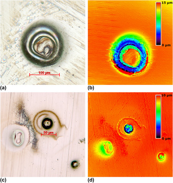
Machining attempts were conducted using both Pt and W tool electrodes. Voltage pulses of 200-ns duration were applied and amplitudes of ∼7 V were obtained. After this procedure, no material removal or surface damage was observed when the 1 M CH3COOH electrolyte was used (not shown here). In contrast, defined structures were obtained when the Pt tool was used in the 1 M CF3COOH solution as shown in Fig. 3(a). However, with the Pt wire tool, electrode machining of a hole was not possible. Instead, a ring-like structure developed as visible in the surface depth profile shown in Fig. 3(b). A reason for this structure might be the nonuniform current distribution at the electrode surface.Reference West and Newman29 Obviously, material removal would occur where the current density was at its maximum, e.g., opposite the rim of the tool electrode.
Holes machined into the surface of a Fe65.5Cr4Mo4Ga4P12C5B5.5 BMG sample in 1 M CF3COOH solution. (a) 50-μm Pt tool electrode optical microscope image and (b) corresponding surface depth map, (c) 20-μm Pt tool electrode and (d) corresponding surface depth map. (color online)

Thus, it is possible that only in this region, the voltage pulse was sufficient to decompose the CF3COO− ion. This explanation implies that it should be possible to machine holes using a sharper tool electrode. Since machining was not successful using W tips (see below), Pt wire electrodes were etched in boiling aqua regia. The process is poorly reproducible, but after several attempts, a tool electrode of ∼20 μm diameter was obtained. Machining attempts conducted with this Pt tool electrode are shown in Fig. 3(c) and the corresponding surface profile in Fig. 3(d). The machined hole in the center of Figs. 3(c) and 3(d) demonstrates that a strongly localized material removal is possible in 1 M CF3COOH solution resulting in a hole with sharp edges. A ring-like structure surrounding the center hole is visible, where the brown area in the microscopic picture corresponds to a region of slight material removal in the surface profile. The oval expansion of this region to the right in both figures [Figs. 3(c) and 3(d)] corresponds to the convection driven by the gas bubbles, which evolve during the machining process. Due to the low stiffness of the thin Pt electrode, the machining is challenging. The electrode is easily bent by gas bubbles. In the lower part of Figs. 3(c) and 3(d), the surface structures resulting from aborted machining attempts are visible.
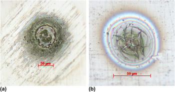
Since W tips are easy to etch and exhibit a high stiffness, machining attempts were conducted with etched W electrodes. A surface after pulsing with 200 ns pulses of ∼7 V using a W electrode of ∼50-μm diameter is shown in Fig. 4(a). The overall structure corresponds to the structure obtained with the 50-μm Pt tool in 1 M CF3COOH solution: a ring-like structure of material loss is visible. Repeating the treatment with a 30-μm W tip resulted in the cracked surface structure shown in Fig. 4(b), which is similar to the structure obtained in 0.5 M H2SO4 solution [Fig. 2(c)].
Optical microscope images of machined structures on an Fe65.5Cr4Mo4Ga4P12C5B5.5 BMG surface in 1 M CF3COOH solution with 200 ns pulses of 7 V amplitude with (a) a 50-μm-diameter W tool electrode and (b) a 30-μm W tool electrode. (color online)

In summary, in CF3COOH solutions, the material of the tool electrode is an important factor for the machining success. In the other electrolytes discussed above, such an effect was not found. This strongly indicates that the machining process of the Fe-based BMG surface in CF3COOH solution is not affected by an oxide layer modification or adsorption of the fluorine containing species but by its decomposition.
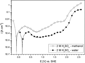
Another approach to pulsed ECMM in the transpassive potential region is the modification of the oxide layer on the metallic glass. It is known that in the case of iron, water plays an important role in the passivation process. Accordingly, iron does not passivate in highly concentrated H2SO4 solution.Reference Mazurkiewicz30 Solutions of low water content have been used for the conventional machining of titaniumReference Piotrowski, Madore and Landolt31 and tantalum.Reference Piotrowski, Madore and Landolt32 During potentiostatic polarization experiments (8 V, 3 M H2SO4—methanol solution) for both metals, an initial decrease of the current density was observed and correlated to an oxide layer formation. Only after about 100 s did the current density increases, leading to mass transfer-controlled dissolution of the metal. However, in contrast to the so-called valve metals Ti and Ta, Fe does not form low conducting oxide layers. The electrochemical behavior of Fe-based alloys during submicrosecond pulses in such an electrolyte has not been investigated yet. However, a comparison of the potentiodynamic behavior of the Fe-based BMG in 2 M H2SO4 solution in water and in 2 M H2SO4 solution in methanol as shown in Fig. 5 indicates that the oxide layer is less protecting in the H2SO4–methanol solution. The free corrosion potential is less noble than in the aqueous solution indicating a higher reactivity. Furthermore, the free corrosion current density increases from ∼20 to ∼90 μA/cm2 and the minimum passive current density increases from ∼25 to ∼150 μA/cm2when the water is replaced by methanol. Additionally, for the machining process, it is important that less current is consumed by the water decomposition reaction and, therefore, more of the current accounts for the alloy dissolution.
Current density–potential curves of Fe65.5Cr4Mo4Ga4P12C5B5.5 BMG recorded in 2 M H2SO4 aqueous solution and 2 M H2SO4methanolic solution with a potential scan rate of 2 mV/s.

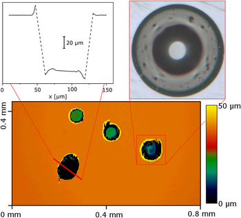
For the first machining tests with the Fe-based BMG, a mixture of methanol and 2 M H2SO4 was prepared using 98% H2SO4, i.e., the electrolyte is not completely free of water. Microholes machined with the use of an etched W-tip as tool electrode and pulse amplitudes of ∼8 V are shown in Fig. 6. In the lower part of the figure, a surface depth map is shown. In the diagonal ordered holes, the pulse length was varied from 50 ns (top right) to 100 ns (middle) and 150 ns (bottom left). An optical microscope image of the hole machined with 150 ns pulses is included in Fig. 6 in the top right side. It shows a smooth surface and a sharp rim of the hole. The elliptic structure in the surface depth map was machined using pulses of 100 ns. Since the color code of the surface depth map does not cover the bottom of this structure, a surface depth line profile was recorded along the red line drawn in the surface depth map and included in Fig. 6. The dashed line in the surface depth line profile represents the rim of the hole, which was not resolved by the measurement system. It is clearly visible that structures of about 100-μm depth can be machined showing that aspect ratios of the machined structures of more then 1:2 are possible. However, when the tool electrode hits the surface on the bottom of the hole, it bends and the machined structure becomes elliptic.
Surface depth profile of holes machined into a surface of Fe65.5Cr4Mo4Ga4P12C5B5.5 BMG in a 2 M H2SO4–methanol electrolyte using pulses of different lengths (see text) and an amplitude of ∼8 V; an optical microscope image of the marked hole and a surface depth line scan along the marked line in the surface map. (color online)

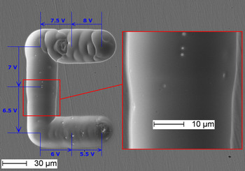
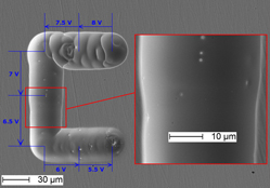
With the use of a mechanical positioning system, more complex structures can be machined. A scanning electron microscope (SEM) image of a typical line structure is shown in Fig. 7. It was machined with a pulse time of 100 ns using a W tool electrode of ∼20-μm diameter and a feed rate of 1 μm every 10 s. The machining process was started with a pulse amplitude of 8 V in the upper right corner of the structure. After moving the tool electrode 20 μm in depth, the lateral machining was then performed as marked by the arrows in the figures whereby the pulse amplitude was lowered in steps of 0.5 V. When a pulse amplitude of 7.5–8 V was used, a significant gas evolution was observed during the machining process. Since the small tool electrode might be bent by the formation and release of gas bubbles, the gas evolution may be a cause for the high roughness of the obtained structure. A pulse amplitude of 6.5–7 V (vertical line in Fig. 7 and inset in Fig. 7) produced a smooth surface. It is furthermore visible in the inset of Fig. 7 that the gap size between the tool electrode and the machined structure slightly decreases with decreasing pulse amplitude. Using pulse amplitudes lower than 6.5 V again reduced the surface smoothness. With an amplitude of 5.5 V, machining was still possible but the tool electrode came in contact with the work piece electrode a number of times, i.e., the tool feed rate of 1 μm every 10 s is already slightly too high.
SEM image of a machined line structure. The tool electrode was moved 1 μm every 10 s as indicated by the arrow. The pulse amplitude of each line segment is noted in the figure. Inset: magnification of the marked area. (color online)

IV. CONCLUSION
Pulsed ECMM is a promising method for the microstructuring of Fe-based BMG surfaces. Highly accurate smooth machined structures can be achieved with the correct combination of electrolyte and probe material. A single-phase defect-free glassy structure appears to be ideal for a homogeneous controlled electrochemical metal removal. The multicomponent nature of the Fe65.5Cr4Mo4Ga4P12C5B5.5alloy with a high metalloid content does not influence the local dissolution process. However, the identification of a suitable electrolyte remains crucial for the success of the machining processes. Therefore, a more detailed understanding of the transpassive dissolution process at ultrashort time scales is necessary and is under investigation.
A systematic study has shown that aqueous solutions of different pH values were not suitable for the micromachining process. Since halide ions in the electrolyte lead to a local breakdown of the oxide layer and pitting corrosion of the glassy Fe65.5Cr4Mo4Ga4P12C5B5.5 alloy, electrolytes containing these ions are not suitable for the micromachining process. However, if these ions can be produced localized, they can contribute to a defined material removal. Another method is the reduction of the water content in the electrolyte to weaken the oxide layer formed at the surface of the alloy and to reduce side reactions (i.e., water decomposition) of the transpassive dissolution. The best machining results were obtained in a methanolic 2 M H2SO4solution in which defined structures with a smooth surface and high aspect ratios can be machined.
ACKNOWLEDGMENT
The German Research Foundation (DFG) is gratefully acknowledged for the support of this work under Grant DFG Ge 1106/10 “Elektrochemische Mikrobearbeitung hochfester metallischer Gläser.”