I. INTRODUCTION
Bulk metallic glasses (BMGs) have many unique properties, e.g., exceptionally high strength, large elastic limit, high hardness, good corrosion resistance, and reduced sliding friction, etc., and are therefore regarded as potential candidates of engineering materials. However, their structural applications are severely stymied by their intrinsic limited plasticity that is confined to narrow regions near dilute shear bands at room temperature. To make BMGs tough, many techniques have been gradually developed. It is commonly accepted that multiaxial stress field is identified to efficiently initiate the proliferation of shear bands and effectively impede their rapid propagation. Among these measures, introducing notches could markedly enhance the plasticity of BMGs, and the toughening efficiency could largely rely on many factors, and the inherent mechanism in the notched BMGs is still poorly understood. On the other hand, understanding notch-related failure is also crucial for the design of reliable engineering structures, but the underlying physical mechanism responsible for the amorphous materials is far from being revealed.
Up to date, many relevant researches have been performed to analyze the effect of notch configurations on the plasticity of BMG structures by experimental method. Qu et al.Reference Qu, Calin, Eckert and Zhang1 investigated the notch tensile behavior of Zr-based BMGs, and found that the tensile strength of the BMGs is insensitive to notches, and notched BMGs exhibit enhanced plastic deformation ability with the formation of shear band zones. Wu et al.Reference Wu, Zhang, Mao and Eckert2 proposed the critical shear offset to explain the strong size effect on the enhanced plasticity of BMGs by taking account of the shear fracture energy density, and pointed out that the failure mode is very sensitive to the notch depth and notch sharpness. Zhao and ZhangReference Zhao and Zhang3 performed the compressive tests on the Zr- and Ti-based BMGs with different notches, and found that the plasticity of the two BMGs can be improved by installing two semicircular symmetrical notches. The improved plasticity may be ascribed to the consequent blocking effect of notches on the propagation of shear bands. Furthermore, Zhao et al.Reference Zhao, Qu, Wu, Lia and Zhang4 experimentally confirmed that the plasticity of Ti-based BMGs with different aspect ratios could be improved by introducing two semicircular notches on the edges of the samples. ZhaoReference Zhao5 experimentally investigated the dependence of the compressive global plasticity on different settings of notch cluster for Zr-based BMGs, and found that a large plasticity could be generated by changing the distance of notch pairs which could make the shear bands interact with each other and block the rapid shear banding progression.
Moreover, the failure mechanism and shear banding evolution were also analyzed by numerical modeling. Sha et al.Reference Sha, Pei, Liu, Zhang and Wang6 performed molecular dynamics (MD) simulation to study the effect of notch depth and notch sharpness on the deformation and failure behavior of BMGs. Increasing notch depth and notch sharpness will lead to a failure mode transition from shear banding to necking. Sha et al.Reference Sha, Pei, Sorkin, Branicio, Zhang and Gao7 conducted MD simulations on the effects of size and shape of a superficial or internal notch on the tensile strength and failure mechanism of CuZr BMG, and concluded that the ultimate strength is insensitive to the notch size and shape, while failure location is notch-sensitive. Sha et al.Reference Sha, He, Xu, Pei, Liu, Zhang and Wang8 examined the effect of aspect ratio on the tensile failure of Cu50Zr50 BMGs with aspect ratios from 2:1 to 12:1. For long BMGs, however, an abrupt unstable shear banding failure is observed, while a combined abrupt unstable shear banding and slow stable shear band sliding is observed for short BMGs. The simulations based on the MD method could clearly interpret the deformation mechanisms at the atomic scale, but their simulation scales are not comparable to real samples,Reference Zhou, Qu and Yang9 and only the qualitative relationship between the microstructure and properties could be obtained. Moreover, these results are highly influenced by some simplifications, e.g., periodical boundary condition, model simplification and others. Furthermore, owing to the restriction of the current computational capability, the strain rates in the MD simulation are in the level of 1010/s, however, the measured strain rates are often in the range of 10−4 to 103/s. The large different in strain rate between the atomistic simulation and macroscopic experiments fatherly indicates that the MD predictions can not compare with the measured results. Recently, finite element method (FEM) was also used to illuminate the shear banding progression in the BMGs. Henann and AnandReference Henann and Anand10 modified the Anand–Su theoryReference Anand and Su11 for large elastic–plastic deformations of BMGs to account for the strongly nonlinear and eventually softening dilatational volumetric elastic response of these materials. They have conducted FEM simulations of fracture initiation at notch tips in a representative BMGs under different conditions. Singh and NarasimhanReference Singh and Narasimhan12 conducted the continuum FEM analysis of tensile loading of nanosized notched BMG specimens using a thermodynamically consistent nonlocal plasticity model to clearly understand the deformation behavior from a mechanics perspective. They conclude that the specimen size scales with an intrinsic material length associated with the interaction stress between flow defects. A transition in deformation behavior from quasibrittle to ductile becomes possible when this critical plastic zone size is larger than the uncracked ligament length. Pan et al.Reference Pan, Zhou, Wang, Li and Gao13 investigated the physical origin of an inverse notch effect in a Zr-based BMG by experiments and MD simulations, and concluded that the seemingly anomalous inverse notch effect is in fact caused by a transition in failure mechanism from shear banding at the notch tip to cavitations and void coalescence. Unfortunately, most of FEM modeling was conducted only based on elastic mechanics and did not consider the plastic deformation and subsequent damage process. To overcome the above mentioned defects in MD and FEM methods, Homer and SchuhReference Homer and Schuh14–Reference Homer and Schuh16 proposed a mesoscale modeling framework for studying BMGs, in which the coarse-grained action of shear transformation zones as the fundamental deformation event. The modeling was controlled through the kinetic Monte Carlo algorithm and the mechanical behavior of the system is captured by FEM analysis. The most advantage of their modeling procedure is that the whole simulations are conducted on the time- and length-scales relevant to both the underlying physics of deformation and experimental methods. The recent advances in the researches of the mechanical behavior of metallic glasses, including the deformation and fracture mechanisms, atomistic as well as continuum modeling and experimental work on elasticity, plastic flow and localization, fracture, fatigue and theoretical developments, can be seen in Schuh's review.Reference Schuh, Hufnagel and Ramamurty17
In this work, a systematic numerical study was performed on the shear banding evolution in notched BMG samples based on the free volume theory, which will be incorporated into ABAQUS code as a user material subroutine (UMAT). The correctness of the present numerical procedure should be firstly verified by comparing with the compression experiments, and then parameter analyses are focused on the effect of notch shape, depth, and configurations on the plastic deformation of various notched BMGs.
II. CONSTITUTIVE RELATIONS OF BMGS
The shear band formation and evolution form fundamental deformation mechanism of BMGs. From microscopic level, shear band formation is believed to be associated with evolution of the local structural order. One atomistic mechanism capturing shear band formation and evolution in BMGs is the free volume model proposed by SpaepenReference Spaepen18 and further developed by Steif et al.Reference Steif, Spaepen and Hutchinson19 From continuum mechanics point of view, the shear band is a result of strain softening and regarded as a strain-localization phenomenon. The free volume model treats the free volume as the state variable, which controls the structural change at the atomic level in BMGs.
The free volume is a measure of the departure from the ideally ordered structure and regarded as the difference between the average atomic volume in real materials and that in the ideally ordered structure. This model assumes that the macroscopic plastic flow in pure shear case occurs as a result of net forward atomic jumps in the direction of the applied stress. The general flow equation is expressed as
 $${{\partial \gamma ^{\rm{p}} } \over {\partial t}} = 2f\,\exp \left( { - {{\alpha \nu ^ * } \over {\nu _{\rm{f}} }}} \right)\,\exp \left( { - {{\Delta G^{\rm{m}} } \over {k_{\rm{B}} T}}} \right)\,\sinh \left( {{{\tau \Omega } \over {2k_{\rm{B}} T}}} \right)\quad ,$$
where, f is frequency of atomic vibration; α is a geometric factor of order 1; ν* is the hard-sphere volume of an atom; νf is the average free volume per atom; ΔG m is the activation energy; Ω is the atomic volume; τ is the applied shear stress; k B is the Boltzmann constant, and T is the absolute temperature. The average free volume νf is treated as the order parameter and control the structural change in BMGs.
The structural rearrangement with applied stress is controlled by competition between a stress-induced disordering and diffusion reordering process. Consequently, the net increase of the free volume is given as
 $${{\partial \nu _{\rm{f}} } \over {\partial t}} = \nu ^ * f\,\exp \left( { - {{\alpha \nu ^ * } \over {\nu _{\rm{f}} }}} \right)\exp \left( { - {{\Delta G^{\rm{m}} } \over {k_{\rm{B}} T}}} \right)\left\{ {{{2\alpha k_{\rm{B}} T} \over {\nu _{\rm{f}} C_{{\rm{eff}}} }}\left( {\cosh \left( {{{\tau \Omega } \over {2k_{\rm{B}} T}}} \right) - 1} \right) - {1 \over {n_{\rm{D}} }}} \right\}\quad ,$$
where n D is the number of atomic jumps needed to annihilate a free volume equal to ν* and is usually taken to be 3–10, and the effective elastic modulus is C eff = E/3(1 − ν). This is still a stress-controlled process. At low stress level, the free volume created by the stress can be readily annihilated and the homogeneous deformation is maintained, while at high stress level, a net increase of the free volume arise and hence shear banding occurs. In the amorphous material, the free volume can be created by the applied loading, and maybe diffused by the thermal activation. The competition between the creation and diffusion process mainly dominate the resulting deformation mode. If the created free volume is immediately annihilated by the brown motion, a homogeneous deformation will be reached, otherwise the sample deforms inhomogenously.
According to the J2-type, small strain visco-plasticity framework, the free volume model can be generalized into multiaxial stress state. The strain rates can be decomposed into the elastic and plastic parts
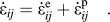 $$\dot \varepsilon _{ij} = \dot \varepsilon _{ij}^{\rm{e}} + \dot \varepsilon _{ij}^{\rm{p}} \quad .$$
The above elastic part is described by the general Hooke's law,
 $$\dot \varepsilon _{ij}^{\rm{e}} = {{1 + \nu } \over E}\left( {\dot \sigma _{ij} - {\nu \over {1 + \nu }}\dot \sigma _{kk} \delta _{ij} } \right)\quad ,$$
with a characteristic time scale t* = tf −1 exp(ΔG m/k BT). After defining the normalized time t*, the equations of (4) and (5) are then differentiated in terms of the normalized time scale t*. The plastic part, i.e., the flow equation can be expressed as
 $$\dot \varepsilon _{ij}^{\rm{p}} = \exp \left( { - {1 \over {\nu _{\rm{f}} }}} \right)\,\sinh \left( {{{\sigma _{\rm{e}} } \over {\sigma _0 }}} \right){{S_{ij} } \over {\sigma _{\rm{e}} }}\quad ,$$
where  $S_{ij} = \sigma _{ij} - {{\sigma _{kk} \delta _{ij} } \mathord{\left/ {\vphantom {{\sigma _{kk} \delta _{ij} } 3}} \right. \kern-\nulldelimiterspace} 3}$ is the deviatoric stress tensor and
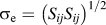 $\sigma _{\rm{e}} = \left( {S_{ij} S_{ij} } \right)^{{1 \mathord{\left/ {\vphantom {1 2}} \right. \kern-\nulldelimiterspace} 2}}$ is the von Mises' stress. It should be noted that a dot over a quantity denotes
 $\left( {\dot □} \right)$ = f −1 exp(ΔG m/k BT) (∂□/∂t), which will be used in the following expression. The symbol “□” denotes the variables that will be substituted in the function. The free volume evolution equation under multiaxial stress state is written as
 $$\dot \nu _{\rm{f}} = {1 \over \alpha }\,\exp \left( { - {1 \over {\nu _{\rm{f}} }}} \right)\left\{ {{{3\left( {1 - \nu } \right)} \over E}\left( {{{\sigma _0 } \over {\beta \nu _{\rm{f}} }}} \right)\left( {\cosh \left( {{{\sigma _{\rm{e}} } \over {\sigma _0 }}} \right) - 1} \right) - {1 \over {n_{\rm{D}} }}} \right\}\quad ,$$
where σ0 = 2k BT/Ω is the reference stress;  $\nu _{\rm{f}} = {{\nu _{\rm{f}} } \mathord{\left/ {\vphantom {{\nu _{\rm{f}} } {\alpha \nu ^ * }}} \right. \kern-\nulldelimiterspace} {\alpha \nu ^ * }}$ is the normalized free volume and β = ν*/Ω.
III. FEM SIMULATIONS
The above constitutive equations are implemented into ABAQUS code by using a user-defined material subroutine UMAT, which is obtained from Gao's work.Reference Gao20 In this framework, the shear band evolution is described by an internal state variable, i.e., the normalized free volume νf as given in Eq. (6). The plastic flow stress is supposed to be a function of the effective Mises stress and the free volume at a certain spatial point. The evolution of the free-volume field depends on the in situ stress state and the current free-volume field. The state-variable field and the stress field should be computed, the formation of the shear band corresponds to a localized increase in the state variable, and the progression of shear banding can be described by free volume density that is denoted by the state-dependent variable, i.e., free volume νf, in ABAQUS package.21
The shear band propagation should be carefully discussed to reveal the failure mechanisms of the BMGs. The initial aspect ratio of the specimen, i.e., the ratio of the initial height (measured along axis-x) to the initial width (measured along axis-y) is 2:1. The initially undeformed FEM mesh of this sample shown in Fig. 1 comprises 5000 ABAQUS CPE4R continuum plane-strain elements. During the computation, all the nodes in the bottom node set are prevented from motion along axis-x. A negative displacement along axis-x is exerted to the single node located at the top-right corner to achieve the desired test strain-rate. The multipoint constraint equation is applied to the rest of the nodes in the top surface to keep their deformation coordinate with the top-right corner node. To suppress rigid-body motions of the sample, the node located at the bottom-left corner is also prevented from moving along axis-y. The remaining nodes in the bottom and top nodes are free to move along axis-y.
(a) Finite element mesh consisting of 5000 CPE4R elements in ABAQUS package for two-dimensional modeling of plane-strain compression and the corresponding boundary conditions exerted during the computation. (b) Contour plot of the initial free volume distribution.

Many prior researchesReference Ke, Zeng, Liu and Yang22,Reference Huo, Zeng, Wang, Liu and Yang23 already suggests that the seemly pure BMGs consist of a solid-like region and liquid-like regions in essential, and such the structural heterogeneity in BMGs would resulted in the nucleation of shear transition zone and the subsequent shear banding progression. To better capture the shear localization in the BMGs, some elements with a slightly lower value of initial free volume act as nucleation sites for shear banding. Also shown in Fig. 1, (b) is the contour plot for the initial free volume ν0 in the BMG sample, and the initial free volume ν0 was presumed to be statistically varied over the elements obeying a Gaussian distribution function with a mean value of 0.05, and a standard deviation of 0.005. Unless otherwise stated, all the following numerical simulations for various notched samples would strictly obey the similar method performed for the unnotched specimen in the calculation.
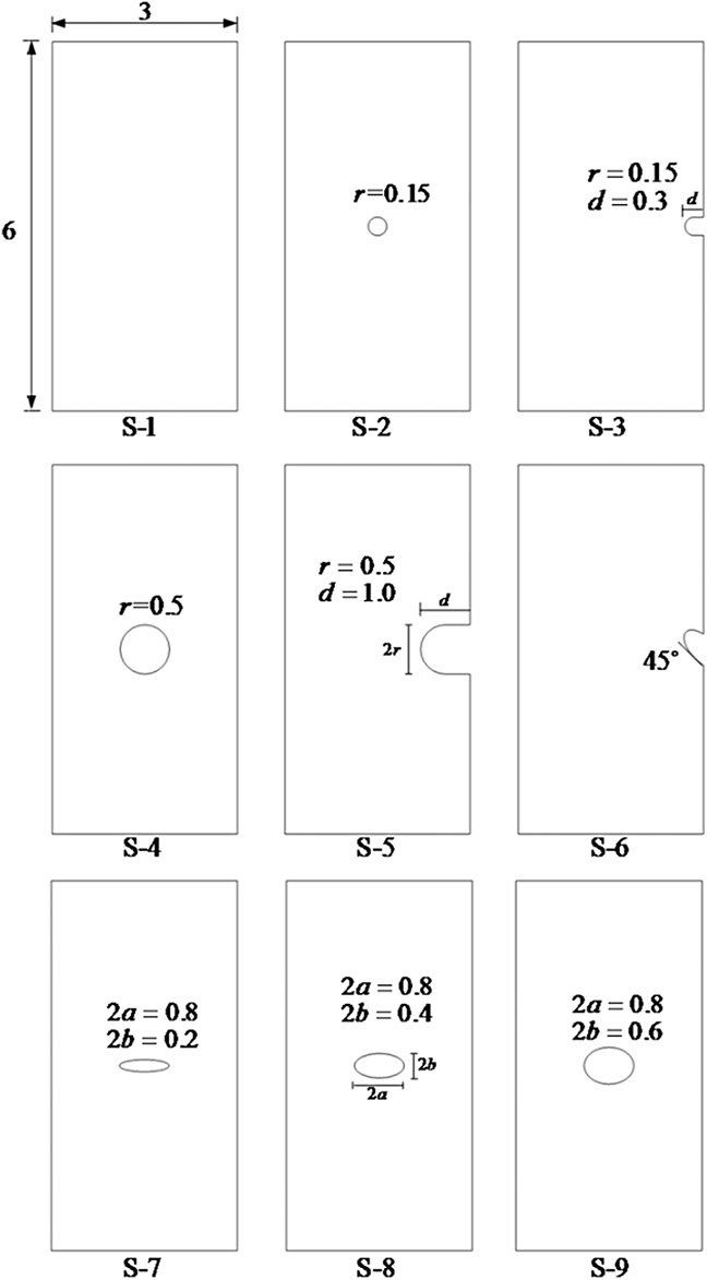
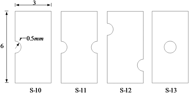
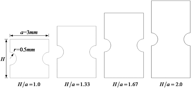
To systematically investigate the influences of notch size, location, shape, configuration, and orientation on the deformation and failure behaviors of BMG samples, Figs. 2 and 3 schematically illustrate the configurations of 13 notched samples. Most of these notched specimens were selected from the experiments available in the published literature, and thus the corresponding numerical simulations could readily compare with the experimental results so as to deeply reveal the inherent failure mechanisms. Furthermore, Fig. 4 illustrates the schematic diagrams for the BMG samples containing two symmetry notches with different aspect ratio.
Schematic of the BMG samples containing of various shaped notches.
Schematic diagrams of the BMG samples with different notch configurations.
Schematic diagrams of the BMG samples with two symmetry notches and different aspect ratio.
IV. RESULTS AND DISCUSSION
A. Verification of the present numerical method
The developed FEM procedure is used to predict the stress (σxx)–strain (εxx) relations in the compression direction for the unnotched BMG sample under the uniaxial compression. The material properties of BMG will be determined by comparing with the measured stress–strain relations continuously until a satisfied agreement between them is reached. The predictability of the present FEM method should be firstly checked by comparing with the experimental result of BMGs.
Figure 5 shows the stress–strain relation of BMG sample under uniaxial compression, and the corresponding contours of shear banding evolution in the BMG specimen during the deformation process, here mesh density N = 5000 was used. The material properties for the BMG are: E = 96 GPa, ν = 0.36, n D = 3, α = 0.35, β = 0.85 and νf/αν* = 0.085. As clearly seen in Figs. 5(a)–5(d), the shear bands are very thin, and dispersed randomly over the BMG sample, which means that the microdeformation energy should be dissipated during the plastic deformation after introducing the perturbation of hard and soft zones in the BMG sample. Once the shear band initiates at εxx = 2.3%, some shear bands will rapidly develop into thicker ones at εxx = 3.0%, and propagate speedily without any impeding effect and grow up into a saturate state at which the macroscopic stress is in a stable level as shown in the stress–strain plot in Fig. 5. Cheng et al.Reference Cheng, Han, Li and Ma24 carefully analyzed the shear banding dynamics in BMGs, and concluded that shear band slid in a stick-slip manner, corresponding to acceleration–deceleration cycle that explains the stop-and-go behavior observed in experiments, which means that the shear banding evolution is a shear-instability process. From a micromechanism perspective, plastic shearing within a shear band ceases when the driving force for shear decreases below some critical value. When deformation continues after shear band is arrested, new shear bands may be activated. This is reflected as a serrated flow in stress–strain curve in the experiments. The stress initiation and propagation of a shear band is associated with a stress drop. Once the shear band is arrested, the stress once again increases to the level necessary to initiate a new shear band. Unfortunately, such microdeformation process is very hard to be realized in the present simulation, and thus no stress fluctuation appears in the corresponding stress–strain relations. The stress–strain curve plotted in Fig. 5 qualitatively shows the compressive stress–strain response of a BMG undergoing homogeneous deformation, i.e., linear elastic deformation until the yield/peak point is reached and strain-softening behavior for the application of deformation beyond the yield point until a steady-state stress level is attained. At point d, the distribution of the free volume within the specimen has reached a steady-state level, i.e., further deformation beyond point d will result in only negligible changes in the specimen's free volume. Hence deformation beyond point d will cause no further shear band growth as the shear band has become fully developed. From the contour plots obtained at point d, we can clearly see shear offsets created on both the lateral surfaces of the BMG sample.
The stress–strain relation of BMG sample under uniaxial compression, and the corresponding contours of shear banding evolution in the BMG specimen at the strains of (a) εxx=0, (b) εxx=2.3%, (c) εxx=3.0% and (d) εxx=3.2%.
Since the present simulations focus on the plasticity of BMGs, the homogeneous deformability before strain localization should be defined firstly. The uniform deformation is given as the slope of the transient between the peak stress and the steady flow stress, which is a known indicator for the degree of flow localization and thus proneness to brittle failure. For instance, the strain stage from origin of coordinate to point d in the stress–strain relation as shown in Fig. 5 regards as the uniform deformation for the BMG sample.
Figure 6 shows the comparison between numerical prediction and the experimental resultsReference Qu and Zhang25 for Vitreloy-1 BMG, here mesh density N = 5000 was used. Since no damage effect was considered during the simulation, the collapse stage in the deformation response of BMG sample could not be well characterized. However, the main part of the deformation process is in good agreement with the corresponding experimental results, which again confirms the accuracy of the developed simulations. Based on the comparison between the modeling and the experimental data, the proposed computational micromechanics model appears to be capable of capturing the constitutive behaviors of BMG materials.
Comparisons between numerical prediction and the experimentsReference Steif, Spaepen and Hutchinson19 for Vitreloy-1 BMG, here the mesh density N = 5000 was used.
Figure 7 demonstrates the dependence of the compressive stress–strain relations on mesh density, here the initial free volume ν0 = 0.05 and the standard derivation S d = 0.005 were adopted. The calculated stress–strain curves are approximately overlapped each other except that the descending stages of the deformation responses scatter a little for different mesh density. The comparison among these computations demonstrates that mesh density has a little influence on the stress–strain relations of BMG sample. Such the exciting numerical result is very attractive to the continuous computational analysis, and mesh density would not be regarded as an important factor to affect the predicted mechanical behaviors.
Dependence of the compressive stress–strain relations on mesh density, here the initial free volume ν0 = 0.05 and the standard deviation S d = 0.005 were adopted.
Figure 8 shows the dependence of the compressive stress–strain relations on the standard deviation of inhomogeneous BMG microstructures, here the initial free volume ν0 = 0.05 was used. The calculated stress–strain curves nearly overlap each other for the models with various standard deviations of S d. The comparison among these computations also shows that statistical distribution of initial defect almost does not affect the predicted stress–strain relations of the BMG samples. Therefore, the inhomogeneous distribution of initial defects would not be considered to be the factor in affecting the predictions.
Dependence of the compressive stress–strain relations on the standard deviation S d of inhomogeneous BMG microstructures, here the initial free volume ν0 = 0.05 was used.
B. The effect of notch configuration on the plasticity of BMGs
To deeply reveal the deformation and failure mechanisms in notched BMG samples, Fig. 9 illustrates the shear band contours as the notched samples collapse. For the present simulation, it should be noted that a shear band could be induced by both the inhomogeneous distribution of initial defect and the introduced notches. Numerical results show that a shear band always originates from the notch root and subsequently propagates rapidly across the sample, resulting in a sudden and rapid stress drop as shown in Fig. 10. The shear band propagation direction is always along a principal shear stress path, forming ∼45° against the loading direction. Comparatively, the notches affect the initiation and propagation of shear bands more greatly than the inhomogeneous distribution of initial defects. The sample would fail completely after the main shear band transects the whole sample. Seen from the contours in Fig. 5, the main shear band would transect the whole sample at point d in the stress–strain curve, and just corresponding to the termination of the uniform deformation and the start of steady-state flow. This connection is firmly supported by the computations for the other samples as shown in Fig. 9. Based on this correlation, the plastic flow becomes much more uniform as compared with the other samples, and two intersecting shear bands strongly prevent the notched sample from strain softening. Therefore, uniform deformation is largely extended while the strain localization is greatly delayed, and correspondingly the malleability is effectively promoted by introducing two symmetric notches.
The final shear band contours in the various notched BMG samples.
The nominal stress–strain relations in (a) and the notch effect in (b) for various notched BMG samples.
As clearly seen from Fig. 10(a), all the curves show a linear elastic behavior in the beginning stage, followed by a nonlinear behavior before reaching the ultimate compressive strength (UCS). After reaching the UCS, all the samples suffer a sudden and rapid stress drop, after which the stress–strain relations go into a steady state with farther compression. The normalized UCS is adopted to characterize the notch sensitivity of the failure strength. The normalized ultimate compressive strength (NUCS) = σn/(σm × Sn/Sm), where σn and σm denote the maximum engineering stress of notched and unnotched sample, respectively, while Sn and Sm represent the net loading area of notched and unnotched samples, respectively. NUCS > 1 is defined as notch strengthening while NUCS < 1 as notch softening. After a simple computation, Fig. 10(b) plots the notch effect in varied notched specimens, and shows that all the BMG samples exhibit the notch strengthening under uniaixal compression.
C. The effect of notch location on the plasticity of BMGs
Figure 11 demonstrates the nominal stress–strain relations for various notched BMG samples and the corresponding contours of final shear banding in these notched BMG samples. It is seen from these curves that the uniform deformation of S-11 sample is far larger than those of the others, and reaches up to 4.5%. While the uniform strains of the other three samples are less than 2.5%. The inherent failure mechanism can be clearly revealed from the associated contours of shear band propagation in these notched BMG samples. Only a main shear band appears along the maximum shear stress plane for the notched samples except the S-11 specimen, and thus the corresponding plastic deformation is very limited. Conversely, the shear banding evolution in S-11 sample is quite different. It should be noted that two main shear bands are formed and intersected strongly with each other, which is called “blocking effect” in Zhao's work.Reference Zhao, Qu, Wu, Lia and Zhang4 The blocking effect can effectively hinder the rapid propagation of shear banding, and largely delays the stress drop for the S-11 sample.
The nominal stress–strain relations for various notched BMG samples and the corresponding contours of final shear banding progression.
D. The effect of sample aspect ratio on the plasticity of notched BMGs
Feng et al.Reference Feng, Li, Yu, Zhang, Ma, Qi and Liu26 analyzed the effects of aspect ratios of Zr-based BMGs on the shear band arrangements through MD simulations and experiments, and their results demonstrate that plasticity increases with the decrease in the aspect ratio. Similarly, the sample aspect ratio may also influence the plastic deformation of notched samples. Figure 12 demonstrates the dependence of the stress–strain relations on the BMG sample size ratio in (a) and dependence of the uniform deformation on the sample size ratio in (b), respectively. Comparatively, all the uniform deformations of notched samples with various aspect ratios are higher than that of BMG sample without notch. Therefore, introducing two symmetric notches can effectively improve the plasticity of BMG samples. However, the uniform deformation does not increase monotonously with reducing the sample aspect ratios, and the experimentsReference Zhao, Qu, Wu, Lia and Zhang4 by Zhao et al. also confirmed the reasonability of the present modeling.
(a) Dependence of the stress–strain relations on the sample aspect ratio, and (b) dependence of the uniform deformation on the sample aspect ratio for the BMG specimens with two symmetric notches.
V. CONCLUSIONS
The numerical modeling was used to analyze the shear banding evolution in BMGs with various notches, and whereby the relationship between the notched configurations and plasticity behaviors was systematically elucidated. Free volume theory was incorporated into ABAQUS code as a user material subroutine UMAT. The present predictions were firstly compared with the experiments to verify the predictability of the developed numerical procedure, and subsequently parametric study was performed to explore the interaction between notches and shear bands in various notched BMG samples. Based on the comparison of the simulations and experimental observation, some typical failure mechanisms were clearly presented. Several main conclusions are reached.
(1) Based on the numerical model with randomly assigned initial free volume value, the mesh density has a little influence on the calculated stress–strain relations of BMG sample.
(2) The inhomogeneous distribution of initial defects has almost no any effect on the predicted stress–strain relations of the BMG sample.
(3) The shear band propagation direction is always along a principal shear stress path, forming ∼45° against the loading direction. Comparatively, the notches affect the initiation and propagation of shear bands more strongly than the inhomogeneous distribution of initial defects.
(4) The present FEM simulation also confirmed the same blocking effect in enhancing the malleability as the observation in the experiment for the BMG sample with two symmetric notches.
ACKNOWLEDGMENTS
This work was supported by the Fundamental Research Funds for the Central Universities (No. B11020079), Jiangsu Provincial Natural Science Foundation (No. BK2012407), National Natural Science Foundation of China (11202064) and Program for New Century Excellent Talents in University. The author would like to thank the anonymous reviewers for their constructive comments.