I. INTRODUCTION
Material extrusion 3D printing (ME3DP) is a technology which relies upon the extrusion of a thermoplastic monofilament through a heated nozzle. Reference Chang and Huang1,2 Originally trademarked as fused deposition modeling (FDM™), there has been a dramatic increase in the use of this technology with rapid growth in the form of desktop models of various grades Reference Roberson, Espalin and Wicker3 and do-it-yourself (DIY) kits due to the expiration of the original patents on the technology in 2009. Reference Crump4 As is the case with other 3D printing technologies, ME3DP presents many advantages over traditional manufacturing techniques, most notably direct computer aided design (CAD) to final part fabrication, the capability to print unique and complex geometries, and short design to product cycle time. The flexibility of ME3DP makes it an attractive manufacturing platform; however, the greatest limitation to this technology is a dependence on amorphous polymeric materials as a feedstock, limiting the amount of printable materials. The lack of a large variety of compatible materials limits the applicability of parts fabricated from ME3DP and inhibits the overall growth of this technology. Currently, two of the most common polymers used by ME3DP are acrylonitrile butadiene styrene (ABS) and polylactic acid (PLA).
One method to increase the variety of materials compatible with ME3DP is the creation of polymer matrix composites (PMCs) where the matrix material is a printable material such as ABS. Indeed, several examples of the creation of printable PMCs can be found in the literature. Reference Masood and Song5–Reference Shofner, Lozano, Rodríguez-Macías and Barrera8 However, in this work, we utilize another strategy to increase the number of ME3DP-compatible materials, the use of polymer blends. While there is not a large body of work in literature performing research on printable polymer blends, there are commercially available amorphous polymer blends such as PC ABS (polycarbonate and ABS) and Ultem 9085 (polycarbonate and polyetherimide), which are both marketed by Stratasys.
The work presented here demonstrates the development of new ABS-based polymeric blends which are compatible with ME3DP, yet have physical properties that are different than pure ABS. The lynchpin of the experiments presented here was the use of the styrene ethylene butadiene styrene (SEBS) copolymer as both a blend with ABS and a compatibilizer agent in the blending of ABS with ultrahigh molecular weight polyethylene (UHMWPE)—a material that is semicrystalline and neither extrudable (without specialized equipment) nor compatible with ME3DP platforms. The use of SEBS as a compatibilizer for blends of polystyrene (PS) and high density polyethylene (HDPE) has been demonstrated in the literature Reference Jelčić, Vranješ and Rek9 and our work here sought to utilize the copolymer block to blend the similar materials ABS and UHMWPE. SEBS has also been widely used as a “rubber toughening” agent for several polymer systems including nylon and polyethylene terephthalate (PET) among others Reference Huang, Keskkula and Paul10–Reference Tanrattanakul, Hiltner, Baer, Perkins, Massey and Moet12 ; and our efforts here strived to achieve a toughened, rubberized ABS which was compatible with ME3DP platforms.
The polymer blending process has several advantages over synthesizing new printable polymers: i) by using known, printable materials as a base, the new blended material will also be compatible with ME3DP platforms; and ii) polymer blending can be done away from large-scale production facilities using small-batch polymer extruders, providing an expanding area for the development of new materials that meets the customer demand for personal 3D printers. This work is focused on altering the physical properties of printable base polymers (in this case ABS) for use in 3D printing through the addition of UHMWPE and the thermoplastic elastomer SEBS. Utilizing and optimizing these three polymeric materials can create unique combinations of properties, based on the individual constituents. For example, ABS is based on three monomers (acrylonitrile, butadiene, and styrene). Of particular interest are the acrylonitrile and butadiene groups, the former is responsible for forming polar bonding between the chains (producing a stronger material) and the latter provides better mechanical resilience. Reference Charles and Carraher13 Likewise UHMWPE offers high toughness, wear and abrasion resistance, and impact strength. Reference Lim, Ishak, Ishiaku, Fuad, Yusof, Czigany, Pukanszky and Ogunniyi14 However, as mentioned before UHMWPE is not compatible with most extrusion equipment and therefore, must be blended with other polymers for 3D printing, as it lacks the melt flow capability required for printing, even above the melting temperature.
In comparison, polymeric elastomers such as SEBS have properties including low melt viscosity, low process temperature, and low distortion during extrusion. Reference Gupta and Purwar15 Also, SEBS has demonstrated high impact strength and high elongation at break. Reference Stricker, Thomann and Mülhaupt16 For these reasons, our work introduced a blended system of SEBS and ABS to increase the elastomeric properties and toughness of ABS. Also, by incorporating a combination of SEBS and UHMWPE to ABS, it was believed possible to achieve the benefits of UHMWPE (toughness) with the properties of ABS and SEBS (printability and relatively low process temperature). To this end, two blend types were fabricated (ABS SEBS and ABS SEBS UHMWPE) to take advantage of these properties and alter one of the most common 3D printing materials (ABS).
II. EXPERIMENTAL
A. ABS/SEBS blends
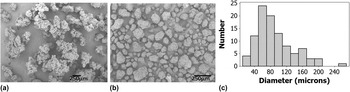
In this study, the ABS used was a CYCOLAC resin MG37CR produced by Sabic (Pittsfield, MA). The SEBS used was a powdered Kraton (Houston, TX, USA) A1536 HU SEBS polymer [Fig. 1(a)] in the form of globular chunks roughly 0.5 mm in diameter. Different blends of ABS were made with varying weight percentages of SEBS: 5, 10, 20, and 50% (in terms of ABS:SEBS ratio 95:5, 90:10, 80:20, and 50:50) and compared with baseline samples created from ABS. The ABS/SEBS blends were pre-mixed and then oven dried. The oven drying process entailed a drying cycle at 100 °C for 14 h followed by a ramp to 110 °C for 1 h and a ramp down to room temperature for an additional 1 h. The mixture was fed to a twin screw extruder/compounder (Dr. Collin Model ZK 25T, Dr. Collin GmbH, Ebersberg, Germany) operating at a temperature of 165 °C, under a pressure of 45 bar, and a screw rate of 70 rpm. The extrusion process was used to create a monofilament of 1.75 mm in diameter which is the standard diameter used by most ME3DP systems.
SEM image of the (a) SEBS and (b) UHMWPE polymer before compounding. The size distribution of the UHMWPE polymer (c) was measured to be 92.6 ± 45 µm.

B. ABS/UHMWPE/SEBS blends
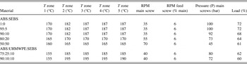
Blends of UHMWPE with ABS using SEBS as a compatibilizer were made using GUR® 1020 UHMWPE (Celeanese, Irving, TX) blended with the same ABS and SEBS materials mentioned above. The UHMWPE was in powder form with a size distribution [Figs. 1(b) and 1(c)] of 92.6 ± 45 µm. The ternary blends tested in this study were based on mass ratios of ABS:UHMWPE:SEBS (90:10:10 and 75:25:10). We found that we were unable to successfully create a printable monofilament when the weight percent of UHMWPE was greater than 25% compared with the ABS base (greater than an ABS:UHMWPE ratio of 75:25). The mixtures were fed to the same twin screw extruder/compounder; however, the operating parameters used for these blends were at a temperature of 195 °C, under a pressure of 72 bar, and a screw rate of 40 rpm. In contrast to both blend systems, the pure ABS filament was created using extrusion parameters of temperature of 175 °C, under a pressure of 54 bar, and a screw rate of 50 rpm. All extrusion parameters for the various blends are shown in Table I and it should be noted that the difference in physical properties necessitated different extrusion parameters which we determined empirically.
Extrusion parameters for the blended materials.

C. Materials testing and characterization
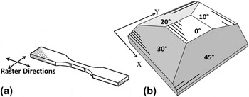
The blended materials underwent tensile testing following the ASTM Standard D638-10 using the Type V dimensions. 17 To verify commercial printability, these samples were printed using a MakerBot Replicator (MakerBot Industries, Brooklyn, NY) material extrusion 3D printer. The print direction of the dog-bone structures was in the XYZ direction [Fig. 2(a)] with a raster height of 0.4 mm and a raster width of 0.4 mm. The raster path was set to produce a maximum filling percentage. A slight modification was made to the MakerBot Replicator; the stock drive gear was replaced with a “hyena” gear as we found this gear to work better with the blended polymer filaments. Additionally, a modified nozzle with a diameter of 0.8 mm was used to print some of the blends as seen in Table II. Machine printing parameters used for each material are listed in Table II and, as was the case with the extrusion process, the 3D printing process demanded different properties based on the material type. The tensile test specimens were subjected to loading using an Instron® 5866 (Instron, Norwood, MA) tensile tester, and the resulting stress, strain, and average Young's modulus were recorded.
(a) Type V tensile test specimen where the raster direction is designated by arrows and hash marks. (b) The structure designed to test surface roughness with surface angles at 10°, 15°, 30°, and 45° with respect to the surface normal.

MakerBot print parameters for all materials.

Fracture surfaces of representative specimens from each sample pool were analyzed with a Hitachi TM-1000 scanning electron microscope (SEM; Hitachi High-Technologies Europe GmbH, Germany) operating at a 15 kV accelerating potential and equipped with a backscatter electron (BSE) detector. SEM imaging allowed fracture surface morphology observations of the blended structures to identify common failure modes within these new material systems. As the goal of this paper was to demonstrate the development of new polymeric blends, a test to measure the printability of the material beyond the printing of mechanical testing specimens was developed. A test structure designed to test the ability to print an inclined plane was developed with surface angles at 10°, 15°, 30°, and 45° with respect to the normal surface of the XY plane [Fig. 2(b)]. The specific angles were chosen based on precedence set in the literature. Reference Pandey, Venkata Reddy and Dhande18 Surface roughness measurements were taken using a Mitutoyo surface roughness tester (model SJ-201P Mitutoyo America Corp., Aurora, IL) and were also made on the flat top surface and bottom surface of the test piece (0° top and 0° bottom in the x and y direction).
III. RESULTS AND DISCUSSIONS
A. ABS/SEBS blends
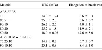
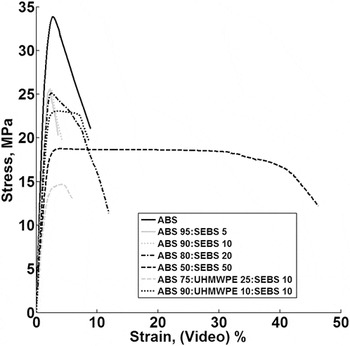
The results of the mechanical testing data are shown in Table III. As can be seen, blends that were 5% and 10% by weight SEBS (the 95:5 and 90:10 ABS:SEBS blends) do not exhibit an improvement in mechanical properties and suffered from a slight decrease in ultimate tensile strength (UTS) of 25.5 ± 2.3 and 26.2 ± 2.5 MPa for 5% and 10% SEBS as compared with UTS of 34.0 ± 1.74 MPa for the baseline ABS samples. The blends with 20% and 50% by weight SEBS (the 80:20 and 50:50 ABS:SEBS blends) also displayed a lower UTS (18.0 ± 0.03 MPa); however, there was a dramatic increase in the percentage of elongation at the breaking strength where the 20% SEBS blend 50% SEBS blend displayed elongation percentage values of 11.9 ± 2.1% and 47.6 ± 5.0% compared with 8.6 ± 3.3% for the baseline ABS specimens. The increase in plastic deformation before fracture is indicative of an increase in toughness over the original ABS base resin. The stress–strain data for all blends are represented graphically in Fig. 3. Each stress–strain curve is a composite curve of every tested sample for a given blend. The data compiling to generate the curves was achieved by a process described in the study of Torrado et al. Reference Perez, Roberson and Wicker19 where a MatLab®-based program was used. By comparing the elongation percentage before failure, it is possible to observe the difference in toughness for the new polymeric blends as compared with the base ABS resin. It is important to note that though there were differences in the mechanical properties of the blends, the materials were still compatible with our ME3DP platform.
Mechanical testing data for all materials tested in this study.

Sample size, n = 5.
Composite stress–strain diagrams generated from tensile test data for all material systems tested in this study. Note the difference in mechanical properties as compared with the base ABS resin. Most notable is the drastic increase in toughness for the 50% by weight SEBS blend.

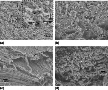
Scanning electron microanalysis of the fracture surfaces from representative specimens from each blend sample pool revealed different characteristics based on the weight percentage of SEBS in the blend. In general, the fracture surface of the tensile specimens is indicative of craze cracking which propagated normal to the direction of applied stress as has also been demonstrated in the literature. Reference Perez, Roberson and Wicker19,Reference Engel, Klingele, Ehrenstein and Schaper20 The prominent features of the fracture surface for the 5% and 10% by weight SEBS blends is the presence of fibrils (indicated by arrows in Fig. 4). These fibrils appear to have torn out of the surrounding matrix, and they decrease in number as the concentration of SEBS increases. In terms of miscibility, this may indicate that ABS is miscible in SEBS because an increase in SEBS concentration corresponds to a decrease in fibrils present. Also, an increase in SEBS concentration causes a shift in the mechanical behavior of the tensile specimens toward a material which is more elastic than ABS alone.
Micrographs of ABS:SEBS blends (a) 95:5, (b) 90:10, (c) 80:20, (d) 50:50. The fracture surfaces of the tensile specimens are indicative of craze cracking, and all fracture surfaces prominently display fibrils, highlighted by black arrows in (a), (b), and (c).

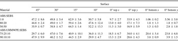
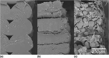
The ABS blends with a concentration of 20% and 50% SEBS were qualitatively different in terms of surface smoothness than the samples printed from pure ABS. These two SEBS blends were subjected to surface roughness testing utilizing the printed test piece discussed above [Fig. 2(b)] and the results are shown in Table IV. As can be seen in the table, the 50% SEBS blend led to the printing of smoother 45° and 30° degree surfaces as compared with the sample printed from ABS. The reason for the improvement in surface roughness for inclined planes is due to the unique characteristics in the way the material is deposited during the printing process which is influenced by the rheological differences between the material systems. As is seen in the SEM images of cross sections from samples printed from selected blends in this study (Fig. 5), the filament shape is still discernable for the sample printed from ABS while the 50:50 ABS:SEBS blend deposits differently. The difference in deposition morphology allows for the creation of smoother inclined planes. The other surfaces of the ABS test piece were comparable for the blends tested.
Surface roughness measurements (Ra in µm) for selected materials.

Sample size, n = 5.
SEM micrographs comparing (a) ABS, (b) the 50:50 ABS:SEBS blend, and (c) the 75:25:10 ABS:SEBS:UHMWPE ternary blend. Note that the ternary blend has a propensity to blend raster layers leading to an overall smoother surface finish for inclined planes.

B. ABS/UHMWPE/SEBS blends
Mechanical testing data for the two ternary blends tested here are listed in Table III. In both blended cases, the material's UTS was weaker than ABS. The average UTS for the ABS:UHMWPE:SEBS (75:25:10) blend was 14.7 ± 0.7 MPa while the ABS:UHMWPE:SEBS (90:10:10) blend produced samples with an average UTS of 23.1 ± 0.8 MPa, as compared with 34.0 ± 1.74 MPa for the baseline ABS samples.
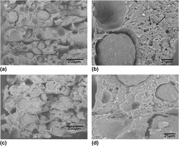
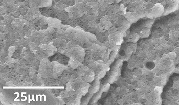
The electron micrographs of the fracture surfaces of representative samples for the two ternary blends (ABS:UHMWPE:SEBS—75:25:10 and 90:10:10) examined in this study are shown in Fig. 6. Analysis of the micrographs confirmed prominent globules of the material in both ternary blends. Comparing the size of the globules to the size distribution of the UHMWPE powder confirms that the globules are most-likely undissolved UHMWPE particles. The surface features of the globules are much smoother than the original powder and are most likely due to particle melt during the extrusion process as the process was above the melting temperature (T m ∼130 °C) of UHMWPE. The particles also appear to pull out of the matrix as there are several cavities and free-to-move particles on the fracture surface. The fracture morphology of the matrix material is more brittle than even the comparable mixtures of ABS and SEBS meaning that it is possible that some of the UHMWPE did dissolve into the ABS matrix or that the SEBS mixed with the UHMWPE as the fracture surface of the matrix resembles the fracture surface of pure ABS (Fig. 7). Also present in the fracture surface of both ternary blends are fibrils and voids where the fibrils pulled out of (highlighted by black arrows in Fig. 6). The mechanics of the fibril tear out is more prominent here than in the ABS:SEBS blend images and may point to a threshold of miscibility between SEBS and ABS.
Micrographs of ABS:SEBS:UHMWPE (a), (b) 90:10:10 and (c), (d) 75:25:10. Large globules are of consistent in size with undissolved UHMWPE. At higher magnifications (b), (d) the undissolved UHMWPE appear to be pulled out of the composite matrix and free-to-move after testing, in addition to have undergone melting.

Representative fracture surface of a tensile specimen printed from ABS.

Surface roughness measurements (Table IV) show that for inclined surfaces, the 75:25:10 ternary blend produced the smoothest surfaces of all materials tested in this study whereas the flat surfaces were among the roughest tested here. As was the case with the 50:50 ABS:SEBS blend, one reason for the smoother inclined planes may be the rheological differences for this blend as compared with the others. Figure 5 compares the print rasters near the edges of specimens for ABS [Fig. 5(a)], the 50% SEBS blend [Fig. 5(b)], and the 75:25:10 ternary blend [Fig. 5(c)]. From the images, it can be seen that the ternary blend has the propensity to deposit in a more spread out fashion than the other blends to the point that it is difficult or impossible to discern the deposition layers. In all cases, the roughness in the x direction was less than that in the y direction due to the fact that in the y direction the test probe traveled against the print raster direction while measurements in the x direction were parallel with the print raster direction. Once again, though the material displayed different mechanical properties as compared with ABS, we were still able to use it as the feedstock on our ME3DP platform.
IV. CONCLUSION
The work presented here had the goal of demonstrating the development of new polymeric blends for material extrusion 3D printing platforms through characterization of mechanical properties, phase morphology, and 3D printer compatibility of novel copolymer blend systems (ABS:SEBS and ABS:UHMWPE:SEBS), each having different physical and chemical characteristics. Toward this goal, the 3D printability of novel binary and ternary polymer blends of varying constituent concentrations was determined by printing standard tensile test specimens and a roughness testing piece with multi-angled inclined planes using a commercially available MakerBot Replicator. In terms of roughness, the 50:50 ABS:SEBS provided smoother flat surfaces and the 75:25:10 ABS:UHMWPE:SEBS blend provided the smoothest sloped surfaces due to the rheological differences as compared with ABS and the other blends in this study. However, we were unable to create a filament when the amount of UHMWPE was increased above 25%. Mechanical testing was also performed on all printable copolymer blends. Through this testing, we observed that blending any amount of SEBS and UHMWPE into an ABS matrix lowered the UTS of printed tensile specimens. Yet, it was also observed when SEBS copolymer blends were loaded greater than 20%, the elongation percentage values (amount of plastic deformation endured by the material prior to failure) increased where tensile test samples printed from the 50:50 ABS:SEBS blend displayed elongation percentage values approaching 50% which is indicative of an increase in toughness of the material.
Characterization of the ABS:UHMWPE:SEBS and ABS:SEBS blends via SEM microanalysis revealed an insolubility of UHMWPE within the ABS matrix as for the ternary blends as well as a solubility threshold between ABS and SEBS for the binary blends. In all cases, ABS blends with altered physical properties were created and demonstrated to be compatible with a desktop grade material extrusion 3D printer. In the case of the binary ABS:SEBS blend, manipulation of the percentage of elongation at break was achieved by changing the ABS:SEBS ratio. While the addition of UHMWPE was detrimental UTS, the result was a 3D printable material capable of printing smoother inclined planes than the ABS base material alone. The work here demonstrates the ability to create 3D printer compatible materials with tailorable physical properties which can be customized for a given application.
ACKNOWLEDGMENTS
The work presented here was supported by a grant from the Intelligence Community Postdoctoral Research Fellowship Program through funding from the Office of the Director of National Intelligence under Grant No. 2012-12071000005. All statements of fact, opinion, or analysis expressed are those of the author and do not reflect the official positions or views of the Intelligence Community or any other U.S. Government agency. Nothing in the contents should be construed as asserting or implying U.S. Government authentication of information or Intelligence Community endorsement of the author's views. Additional support came from the National Aeronautics and Space Administration (NASA) under Grant No. 282002-8784. The facilities of the W.M. Keck Center for 3D Innovation and the Department of Metallurgical and Materials Engineering located at The University of Texas at El Paso were used for fabrication, SEM imaging, and material testing throughout this research project.