Introduction
Nano- and micro-instrumented indentation techniques are now common to characterize the metallic materials. Some of the obvious advantages of these techniques are a small tested volume, which enables characterization of material gradients and heterogeneous materials, and a simple analysis method that provides hardness and elastic modulus [Reference Oliver and Pharr1]. However, when it comes to polymers, the application of the Oliver and Pharr method revealed to be questionable. Many authors [Reference Briscoe and Sebastian2, Reference Cheng and Cheng3, Reference Cheng and Cheng4, Reference Oliveira, Costa, Teixeira and Costa5, Reference Hardiman, Vaughan and McCarthy6, Reference Chudoba and Richter7, Reference Feng and Ngan8, Reference Chattaraj, Pant and Nanavati9, Reference Beyaoui, Mazeran, Arvieu, Bigerelle and Guigon10] noticed difficulties in fitting of the unloading curve, which is necessary to obtain material stiffness and contact depth, since this curve presented a “nose,” i.e., negative stiffness at the beginning of the unloading. This is usually attributed to the viscoelastic behavior of polymers, which results in a retardation of material response to the loading phase superposed to the unloading recovery behavior. There are several ways to avoid the problem of negative stiffness and to improve the fitting of the unloading curve. For instance, a holding period is often introduced at the maximum load. However, the duration of hold has a significant impact on the values of elastic modulus and hardness [Reference Oliveira, Costa, Teixeira and Costa5, Reference Hardiman, Vaughan and McCarthy6, Reference Chudoba and Richter7]. A combination of minimal duration of hold and minimal unloading speed was suggested by Feng and Ngan [Reference Feng and Ngan8] to obtain instantaneous elastic modulus clear of viscoelastic effects. Recently, Hardiman et al. [Reference Hardiman, Vaughan and McCarthy6] suggested to fit the unloading curve and to evaluate the stiffness not at the maximal load, but at the point of zero creep and relaxation drift, where the viscoelastic effects from loading disappeared. Chattaraj et al. [Reference Chattaraj, Pant and Nanavati9] suggested to use a better fitting procedure (smoothing LOESS) of the unloading curve from 20 to 95% that minimizes the residuals. The part of the curve to fit is also not standardized for polymers. Beyaoui et al. [Reference Beyaoui, Mazeran, Arvieu, Bigerelle and Guigon10] demonstrated that the bounds of 20–100%, 20–98%, and 50–100%, usually used by other authors, give different results in terms of elastic modulus. Nevertheless, all these studies use the Oliver and Pharr method to obtain the stiffness and contact depth by deriving the fitted unloading function.
Although the quality of fit can be improved by the above-cited methods, the results obtained by Oliver and Pharr method are not necessarily valid. Some authors [Reference Briscoe and Sebastian2, Reference Hardiman, Vaughan and McCarthy6, Reference Beyaoui, Mazeran, Arvieu, Bigerelle and Guigon10, Reference Tranchida, Piccarolo, Loos and Alexeev11] highlighted the fact that the fitting of the unloading curve obtained on polymers gives a power law exponent inconsistent with the elastic solution it is based on. Indeed, according to Sneddon’s analytical solution [Reference Sneddon12] for indentation of an elastic medium, the power law exponent is 1 for flat punch, 1.5 for a paraboloid of revolution, and 2 for a conical indenter. However, for an elasto-plastic material indented with a cone or pyramid, the experimentally determined power law exponent is usually lower than its theoretical value of 2. This is explained by Pharr and Bolshakov [Reference Pharr and Bolshakov13, Reference Bolshakov and Pharr14] through finite element method simulations both by the fact that the surface in contact is not flat as in Sneddon’s case but matches the shape of the indenter, and by the complex elasto-plastic deformation processes under the surface. In the case of polymers, this coefficient is usually higher than 2 even after the holding period at maximum load or the correction of unloading fitting procedure [Reference Hardiman, Vaughan and McCarthy6, Reference Beyaoui, Mazeran, Arvieu, Bigerelle and Guigon10, Reference Tranchida, Piccarolo, Loos and Alexeev11]. This inconsistency of Sneddon’s analysis, and therefore the Oliver and Pharr method, for polymers was already pointed out by several studies [Reference Briscoe and Sebastian2, Reference Tranchida, Piccarolo, Loos and Alexeev11]. Tranchida et al. [Reference Tranchida, Piccarolo, Loos and Alexeev11] even went further saying that using of the Oliver and Pharr method for polymers is improper, and the main reason is not in the contribution of pile-up or viscoelastic effects. Indeed, the use of Oliver and Pharr method assumes purely elastic behavior at the beginning of unloading, which is independent on rate or time of loading/unloading, and perfect contact conditions assuming the material surface to fit closely the surface of indenter. Both these assumptions are generally not true for polymers.
A recent paper by Herbert et al. [Reference Herbert, Phani and Johanns15] gives a critical review of current methods to characterize viscoelastic materials. According to Herbert et al., time-domain viscoelasticity can be characterized by indentation creep or relaxation tests which give the creep compliance function or the stress relaxation modulus at long time scale. However, among the most significant issues with these methods are the thermal drift, which can become very significant in long tests, and experimental difficulties in a step loading which require a correction of the results [Reference VanLandingham, Chang, Drzal, White and Chang16, Reference Baral, Guillonneau, Kermouche, Bergheau and Loubet17]. Moreover, the results of indentation creep tests often do not superpose with macroscopic creep tests and demonstrate nonlinear viscoelastic behavior [Reference Tweedie and Van Vliet18]. The stress relaxation test has an advantage of maintaining constant affected volume and constant contact area during the test. However, a difficulty to conduct this test is that most of commercially available nanoindentation apparatuses are load-controlled. The use of a feedback loop is necessary to maintain the displacement constant, which results in a significant overshoot at the beginning of the test [Reference Baral, Guillonneau, Kermouche, Bergheau and Loubet17].
The frequency-domain viscoelasticity is characterized by dynamic indentation tests where the load is oscillated around some positive values with a constant and very small amplitude. The phase lag is then measured and correlated through a single-degree of freedom simple harmonic oscillator model to storage and loss moduli of the material. This experiment enables to characterize short-time viscoelasticity at frequencies of 1–300 Hz. There are a significant number of assumptions and experimental precautions to be made if this method is used to determine the viscoelastic moduli. Moreover, the obtained moduli are usually rather different from the results of dynamic mechanical analysis (DMA) [Reference Herbert, Phani and Johanns15, Reference Herbert, Oliver and Pharr19, Reference White, Vanlandingham, Drzal, Chang and Chang20], which makes them difficult to validate.
A possible explanation of difficulties to characterize time dependency of polymers with indentation is that the dynamic indentation and indentation creep tests are based on the assumptions of linear viscoelasticity and absence of plasticity. Both assumptions seem strong in view of very high local stresses and complex stress field in indentation with pyramidal indenter. To include plasticity in viscoelastic model, some authors [Reference Oyen and Cook21, Reference Zhang, Zhang, Zeng and Shen22] suggest to use simple rheological arrangements of spring, dashpots, and sliding frictional elements. This kind of models is rather simple to implement, and the fit they provide is very close to the experimental curves. However, the obtained viscoelastic and plastic parameters are often far from the ones measured in macroscopic tests, raising a problem of validation of these results.
In view of the highlighted difficulties in the existing theoretical solutions to closely fit the experimental data with a sufficient degree of freedom to represent all aspects of polymer behavior, it seems that the problem might be in the design of experiment. Although the loading–unloading experiment ignores time dependency of polymer providing hardness and elastic modulus, the dynamic indentation experiment describes short-time viscoelasticity only, and the indentation creep experiment provides long-time viscoelasticity failing to characterize short times due to nonzero loading time. Moreover, none of these experiments provide results matching similar in nature macroscopic tests. It seems, therefore, that one of the ways to improve the polymer characterization with indentation is to use a different indentation experiment that would tackle all aspects of constitutive behavior in one test combining the strengths of the existing methods and avoiding their difficulties. This is the subject of the present paper.
In the present study, a new experimental method is suggested to probe time-dependent behavior of polymers by instrumented indentation. The method consists of application of many cycles of loading/unloading to similar load with similar loading rate. The analysis of polymer time-dependent behavior is implemented by following the evolution of instantaneous elastic moduli, hysteresis loops, ratcheting, and recovery. These parameters and their evolutions are compared qualitatively, and quantitatively where possible, to the results of macroscopic cyclic tension and shear tests carried out on the same polymer with the same frequencies. The cyclic indentation method is applied to study the time-dependent behavior of a thermosetting epoxy resin PR520, an amorphous thermoplastic polymer poly(methyl methacrylate) (PMMA), and a semi-crystalline polymer high-density polyethylene (HDPE). The strength of the suggested analysis method is that it is not based a priori on any assumption of constitutive behavior and explores both short and long time scales. However, the results obtained on three tested polymers indicate some signatures of viscoelastic and plastic behavior that are discussed throughout the paper.
Cyclic indentation method—theoretical background
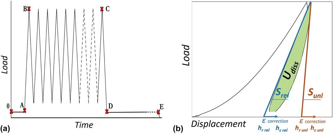
Figure 1(a) presents the experiment carried out in this study. It comprises an initial hold for thermal drift correction, a number of loading–unloading cycles at constant and similar loading and unloading rate, and a load hold at the end of test to evaluate material recovery.
(a) Loading path of the cyclic indentation test and (b) schematic of the cycle analysis.

The unloading  $\left( {E_{{\rm{unl}}}^*} \right)$ and reloading elastic moduli
 $\left( {E_{{\rm{rel}}}^*} \right)$ are calculated from unloading and reloading stiffness (S unl and S rel), as shown in Fig. 1(b), according to the Oliver and Pharr [Reference Oliver and Pharr1] analysis method. This method makes use of Sneddon’s elastic solution [Reference Sneddon12] to analyze the unloading curve assumed to be purely elastic at the initial part. The contact stiffness S is estimated as a derivative dF/dh at the maximum load from the power law fit of the unloading or reloading curve
 $$F = A{\left( {h - B} \right)^m}\quad ,$$
where F and h are load and displacement, respectively, and A, B, and m are fitting coefficients. Each reloading and unloading curve is fitted on 20%–98% of maximum load range. The reduced elastic modulus E r is determined from the contact stiffness S and the projected contact area A p as follows:
 $${E_{\rm{r}}} = {{\sqrt \pi } \over {2\beta \sqrt {{A_{\rm{p}}}} }}S\quad ,$$
where β is the indenter square shape factor (β = 1.034 for Vickers indenter), and the projected contact area depends on the contact depth h c as:
 $${A_{\rm{p}}} = {C_0}h_{\rm{c}}^2 + {C_1}{h_{\rm{c}}} + {C_2}h_{\rm{c}}^{{1 / 2}} + {C_3}h_{\rm{c}}^{{1 / 4}} + {C_4}h_{\rm{c}}^{{1 / 8}} + {C_5}h_{\rm{c}}^{{1 / {16}}}\quad .$$
The coefficients C 0, … C 5 are determined through the area calibration procedure. For a perfectly elastic material, the surface outside the contact tends to sink in, resulting in the contact depth lower than the maximal displacement [see Fig. 1(b)]. The contact depth h c is estimated as follows:
 $${h_{\rm{c}}} = {h_{\max }} - \varepsilon {{{F_{\max }}} \over S}\quad ,$$
where h max and F max are the maximal displacement and force, respectively, of each unloading or reloading curve and ε is a constant related to the indenter geometry (ε = 0.75 for Vickers indenter). The reduced modulus E r is then corrected by the elastic modulus E i and Poisson’s ratio νi of the diamond indenter to obtain the elastic modulus of tested material E* as follows:
 $${E^*} = {1 \over {{1 \over {{E_{\rm{r}}}}} - {{1 - \upsilon _{\rm{i}}^2} \over {{E_{\rm{i}}}}}}}\quad .$$
This elasto-plastic solution for contact will be used for a time-dependent material by considering the elastic modulus E* to be instantaneous at the moment of each top of the cycle. Thus, E* will be referred to as instantaneous elastic modulus in the following. It is noteworthy that the hypothesis of instantaneously elastic unloading and reloading implies that all the plastic deformations are installed during the first loading.
As shown in Fig. 1(b), a hysteresis is observed between reloading and following unloading. Tracing the amount of dissipated, or absorbed, energy U diss throughout the cycles of each test is a way to describe the viscoelasticity or, more generally, time dependency. The area between each reloading and unloading is calculated through numerical integration with a trapezoidal method. The ratio of dissipated energy to the total energy U tot, which is the sum of absorbed and recovered energies calculated as the integral of loading curve, provides a part of absorbed energy at each cycle as follows:
 $$\eta = {{{U_{{\rm{diss}}}}} \over {{U_{{\rm{tot}}}}}} \times 100\% \quad .$$
Results and discussion
Cyclic behavior
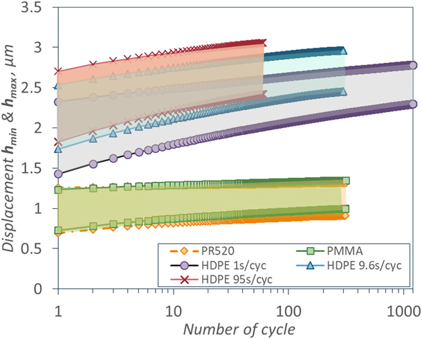
The analysis described above was applied to a range of materials to evaluate their time dependency from the indentation experiment. Firstly, the experimental method was tested on fused silica since this material is known to exhibit perfectly elasto-plastic behavior and no hysteresis [Reference Oliver and Pharr1, Reference Shuman, Costa and Andrade23]. The resulting load–displacement curves, shown in Supplementary material, confirm the superposition of loadings and unloadings of 20 cycles on fused silica approving the use of the developed method on the given equipment. Three different materials were chosen to study indentation time-dependent behavior of polymers. These were a thermoset resin PR520 epoxy, an amorphous thermoplastic PMMA, and a semi-crystalline thermoplastic HDPE. While at room temperature the former two polymers are significantly below their glass transition, the amorphous phase of HDPE is at its rubbery state. Therefore, the time dependency of this material is expected to be more pronounced at room temperature and will be studied at three different loading rates. Figure 2 outlines the maximal and minimal displacements of cyclic tests with constant loading/unloading rate. The tests of 300 cycles of 9.6 s per cycle on PR520 epoxy and PMMA and the tests of 1200 cycles of 1 s per cycle, 300 cycles of 9.6 s per cycle, and 60 cycles of 95 s per cycle on HDPE are presented in this figure and in Supplementary Material.
Maximal and minimal displacement evolutions during indentation cycling of PR520 epoxy, PMMA, and HDPE.

It is clear that all these polymers present hysteresis under cyclic indentation in contrast with fused silica. The hysteresis seems to reduce with cycles, but does not disappear at the last tested cycle for all materials and rates. The HDPE seems less hard than the epoxy and PMMA since its maximum depths of the first cycle is significantly higher, which is in consistency with their macroscopic mechanical properties. The HDPE also distinguishes by a significant shift of the loops to the higher depths with cycling. Moreover, the loading/unloading rate has a significant effect on the shape and position of indentation loops of HDPE. In the following sections, these loops will be analyzed quantitatively and the material and rate effects will be discussed. In addition, the cyclic behavior of HDPE will be discussed with respect to its macroscopic tensile and shear cyclic behavior measured on a sample cut from the same pipe as in this study and published by Nguyen et al. in 2014 [Reference Nguyen, Castagnet and Grandidier24].
Instantaneous elastic moduli
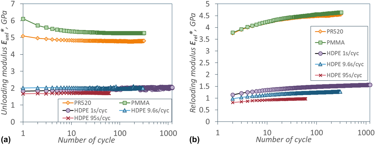
The unloading and reloading instantaneous elastic moduli of three polymers calculated with the procedure described above are presented in Figs. 3(a) and 3(b) as a function of the number of cycles. One can see that both the values and the evolutions with cycles of unloading modulus are rather different from those of reloading modulus. In this section, the arguments in favor of and against both moduli will be presented and discussed.
(a) Unloading and (b) reloading instantaneous elastic moduli deduced from the cyclic indentation tests on PR520 epoxy, PMMA, and HDPE at three loading rates.
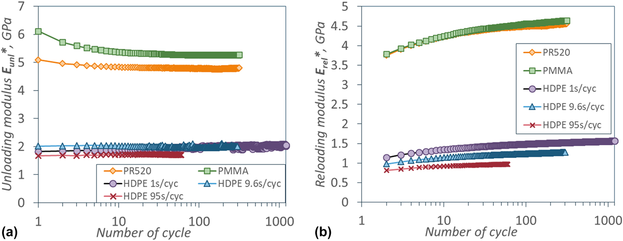
The elastic or elasto-plastic solution for contact assumes time independency of the response and gives superposition of unloading and reloading. In this case, the contact depth h c and the contact stiffness S are similar for reloading and unloading. Since both moduli are calculated at the same penetration depth h max, the projected contact area must be the same. However, the hysteresis loops observed on polymers result in the different instantaneous elastic moduli calculated from reloading and unloading at the same moment of time. This might be due to both an inaccuracy of evaluation of contact stiffness and a difference of material response to reloading and unloading.
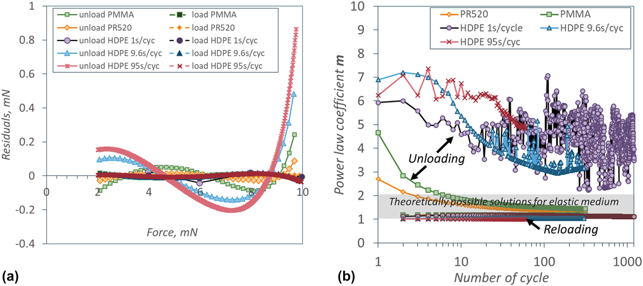
Both loading and unloading are affected by the viscoelasticity of polymer, but in a different way. During the unloading, the lag between applied force and displacement response manifests itself through an addition of retardation phenomena after loading to the fast recovery due to unloading. This is well known in the literature experimentally [Reference Briscoe and Sebastian2, Reference Cheng and Cheng3, Reference Cheng and Cheng4] and was shown with analytical and finite element models for linear viscoelastic materials [Reference Cheng and Cheng3, Reference Vandamme and Ulm25]. A change of regime during unloading (rapid decrease in retardation component) makes it difficult to fit the unloading curve accurately with the power law, especially at the maximal load where the stiffness and modulus are evaluated. Figure 4(a) presents the plot of residuals between the loading and unloading curves and the fitted power law function [Eq. (1)] for the first cycle. It is clear that the power law fit is poor for unloading of all three polymers. The rate effect on the quality of fit is also observed: the slowest tests are the farthest from the power law, which is consistent with the viscoelastic behavior [Reference Cheng and Cheng3, Reference Vandamme and Ulm25]. It is also possible that the first values of unloading displacement and force are affected by a loading overshoot, i.e., the incapacity of the indentation equipment to follow exactly the required change of loading slope.
(a) Plot of residuals for the first unloading and first reloading and (b) power law coefficients for the whole test of loading and unloading curves fitted with Eq. (1).
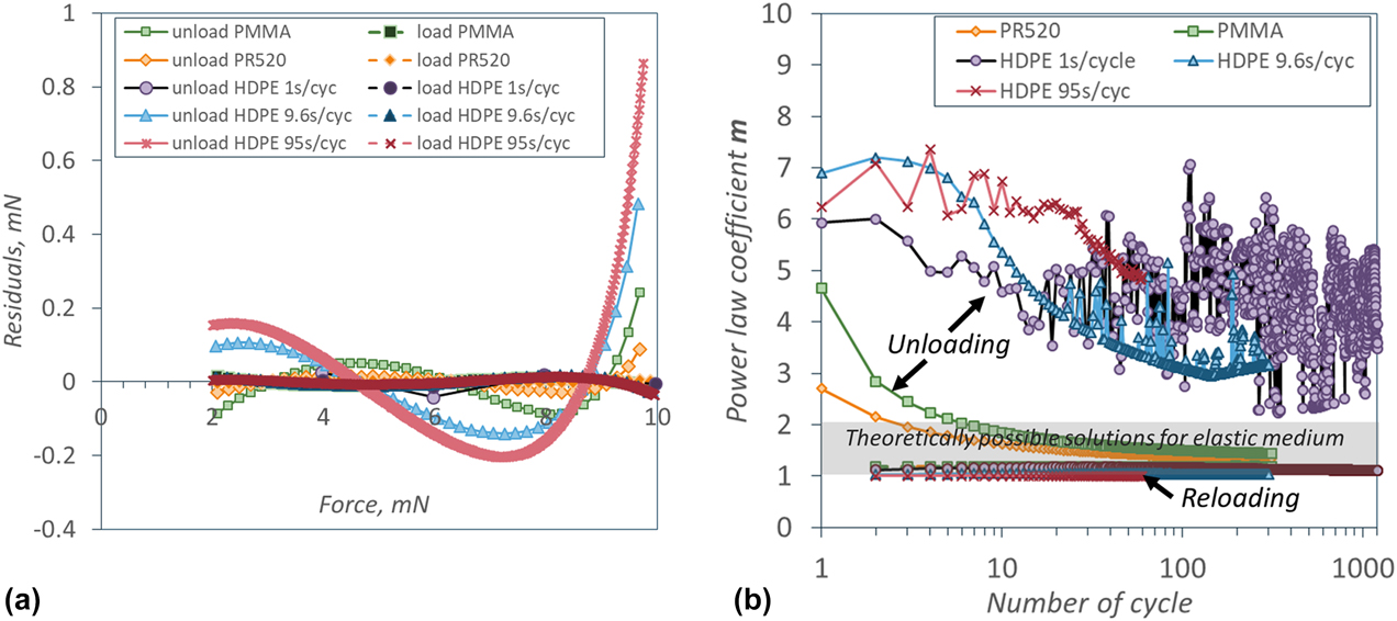
For all these reasons, the unloading curves are inconsistent with Sneddon’s elastic solution, which manifests itself in high power law exponent m, see Fig. 4(b). Indeed, for three tested polymers the power law exponent m is higher than 2, which is not possible theoretically since it means concave shape of the indenter. Figure 4(b) demonstrates that only PMMA and PR520 epoxy enter in the zone of theoretically possible solutions of 1 < m < 2, but only after several cycles. All unloading curves from all tests on HDPE are inconsistent with Sneddon’s solution, and therefore the method of Oliver and Pharr, even for very high loading rate and high number of cycles. Both the quality of fit and its consistency with the elastic contact solution [Figs. 3(a) and 3(b)] improve with cycles, which can be explained by a stabilization of the viscoelastic behavior and an establishment of a stable contact area. A similar effect of cycling on the m coefficient and unloading elastic modulus  $\left( {E_{{\rm{unl}}}^*} \right)$ was observed on PMMA and PC by Beyaoui et al. [Reference Beyaoui, Mazeran, Arvieu, Bigerelle and Guigon10] despite differences in loading cycles with the present method. The authors applied 30 cycles of indentation load–hold–unload with constant loading rate/load ratio and long holding time at each cycle, arguing that in these conditions, the loading and unloading were purely elasto-plastic and the creep during holding period was viscoelastic. However, the decrease in the m coefficient from more than 3.5 to less than 2 with cycles witnesses that even in this loading history, where all precautions were taken to avoid viscoelastic contributions on unloading, the unloading behavior is still inconsistent with Sneddon’s solution.
A reloading curve describes the material's response to an increase in load superposed with a retarded viscoelastic recovery after the unloading. The load overshoot has no influence on it. The imprint is already formed during previous loading, and the indenter does not lose the contact between cycles. This results in a significantly better quality of power law fit for reloading curves than for unloading, which is supported by Fig. 4(a). The residuals are very small and similar for all tested polymers and rate conditions. Figure 4(b) shows that the power law coefficient m of reloading fit is close to 1 for three tested polymers at all used loading rates and all cycles. Moreover, it is possible to obtain m = 1 if the fitting range is adapted (e.g., 50–100%) for the sake of reducing viscoelastic effects from the unloading even further. According to the concept of the equivalent indenter shape introduced by Pharr et al. [Reference Pharr and Bolshakov13], this means that the reloading is close to the flat punch condition: contact stiffness independent of penetration and constant contact area.
Based on these considerations and the results presented in Figs. 3(a) and 3(b), we can conclude that the determination of elastic modulus from reloading curve is more meaningful than from unloading curve for polymers. The advantages of determination of reloading modulus instead of unloading on metals were discussed by Shuman et al. [Reference Shuman, Costa and Andrade23]. They observed that while up to 100 mN the reloading and unloading elastic moduli were similar, there was a significant difference beyond this range, unexpectedly for elasto-plastic materials. The hysteresis measured on the metals was explained by the reverse plasticity, which affected unloading. For a range of tested metals, the reloading modulus was significantly closer to the tensile modulus. Although the conclusion of the work of Shuman et al. and ours are similar, the reasons of better reloading behavior differ due to the physics at atomic or macromolecular scale.
There are at least two ways to improve the accuracy of the instantaneous elastic modulus further. Firstly, the contact depth, which intervenes in the calculation of projected contact area, depends on either the sink-in or pile-up behavior is observed. Since at this moment, to our knowledge, there is no reliable method to measure pile-up of polymers at the maximum load during indentation, the sinking-in behavior is assumed in this study. However, one should have in mind that if such a method appears in the future, the instantaneous elastic moduli obtained by the cyclic indentation method would need to be simply shifted to lower values by correcting the contact depth in Eq. (4) and the projected area in Eq. (3). Secondly, the confinement of the material under indenter has an effect on the measured elastic modulus [Reference Hardiman, Vaughan and McCarthy6, Reference Tranchida, Piccarolo, Loos and Alexeev11]. In particular, hydrostatic pressure is known to increase the elastic modulus as by Birch equation. This correction is not used in the present work since the knowledge of the constraint factor and Poisson’s ratio is required.
Once the unloading elastic modulus was discarded, it is interesting to discuss the evolution of the reloading instantaneous elastic modulus with cycles presented in Fig. 3(b). This evolution describes long-time viscoelasticity at the time scale of the test.
Comparison of indentation with tension and shear cyclic response
The periodic zigzag loading with a high amplitude and low frequency makes this test very different from the dynamic indentation test or DMA. Therefore, the evolution of the instantaneous elastic modulus with cycles is compared with the macroscopic tests with similar loading history. Macroscopic cyclic tension and shear tests on the HDPE used in this study were conducted by Nguyen et al. [Reference Nguyen, Castagnet and Grandidier24]. The frequency of 0.01, 0.05, and 0.1 Hz and the maximum stress lower than yield were imposed. It revealed an initial increase in dynamic elastic modulus, describing the tilt of the loop, before the stabilization after around 20 cycles for both types of loading. The stabilized state meant that the area of hysteresis loop and the dynamic elastic modulus remained constant for all cycles after the 20th. The mean strain, however, continued to increase shifting the loops to the right on the stress–strain plots. The stabilization of the loop is explained by the equilibrium between several processes of internal dissipation as defined by viscoelasticity theory. In the cyclic indentation tests presented here, the instantaneous elastic modulus continues to increase until the end of the test for three tested polymers [see Fig. 3(b)]. However, this increase is faster for the first 10 cycles and rather constant furthermore. The origin of this difference with macroscopic behavior is still unclear, but some possible explanation could be in the small volume of indentation test comparable with the size of microstructure, the complex stress and strain distribution with local plasticity, and the force-controlled mode of test. Nevertheless, the dependency of the instantaneous elastic modulus on frequency is very similar to the one observed in macroscopic tests and consistent with viscoelastic theory: macromolecules become stiffer with higher loading rate. It is also interesting to note that the reloading instantaneous elastic modulus, at the end of the test of 1 s/cyc, or 1 Hz, is 1.56 GPa, which is very close to 1.58 GPa measured by DMA at 1 Hz and 20 °C.
Energy analysis
In addition to the unloading or reloading curves that enable to evaluate instantaneous elastic properties, the whole hysteresis loop can be analyzed with the aim to shed light on material constitutive behavior without any a priori assumption. Some of significant advantages of this analysis are that it does not depend on pile-up or sink-in phenomena or on a fitting procedure as previously discussed parameters. As detailed in Cheng and Cheng [Reference Cheng and Cheng3], the energy ratio η [Eq. (6)] brings very important information for elasto-plastic materials to describe a part of plastic dissipation. Their finite element simulations and experimental results showed that the energy ratio η is directly proportional to a ratio between final and maximal depths h f/h max when h f/h max > 0.4 independently of the indenter cone angle. Same authors used finite element simulations to find that this energy ratio η is also proportional to the ratio of hardness and reduced elastic modulus H/E*. This means that the material properties can be indirectly probed by this ratio.
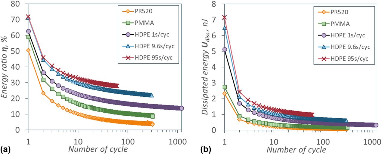
The energy ratio η is plotted in Fig. 5(a) for three polymers as a function of cycles. It shows that at the first cycle, from 50 to 70% of total energy is dissipated for three tested polymers, which is similar to the amounts measured on metallic materials. However, since the dissipative processes involved in the indentation of polymers are different from those examined by Cheng and Cheng, the relationship between the energy ratio and mechanical properties as E* or H cannot be applied directly, but the evolution of dissipated energy with cycles might be related to viscoelasticity and plasticity.
(a) The energy ratio and (b) dissipated energy evolutions with cycles for PR520 epoxy, PMMA, and HDPE at three loading rates.
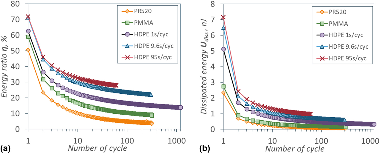
The evolution of dissipated energy with cycles for three studied polymers is presented in Fig. 5(b). All three polymers demonstrate similar dissipative behavior: the dissipation in the first cycle comprising the initial loading and first unloading is high, and then it drops significantly at the second cycle and continue to decrease smoothly up to the end of test. It seems that the dissipated energy tends to zero for all polymers, but it is difficult, if not impossible, to verify it experimentally. The drop of energy between the first and the second cycles can be explained by the change of dissipative regime from viscoelasto-plastic to viscoelastic. The continuing decrease in dissipated energy from the second to last cycle indicates no other change of dissipative mechanism.
The dissipative behavior of HDPE can again be compared with the results of tension and shear macroscopic cyclic tests [Reference Nguyen, Castagnet and Grandidier24], where the loop area decreased in first 20 cycles and then stayed constant and positive for the rest of the test up to 1000 cycles. In contrast with the loop area in macroscopic tests, the dissipated energy in indentation does not stabilize at the end of the test, but its rate of change also slows after around 10 cycles. This is a part of the same phenomenon that was described for the instantaneous elastic modulus. The frequency effect on the loop area on macroscopic stress–strain curves and dissipated energy in indentation is also similar and consistent with viscoelasticity: higher loading rate provides thinner loops due to limited macromolecular movements.
Displacement analysis: cyclic indentation creep and recovery
Many materials, and in particular the HDPE used in this study, present ratcheting behavior in macroscopic cyclic tests under tension, compression, shear, and multiaxial loading [Reference Nguyen, Castagnet and Grandidier24, Reference Kang26, Reference Chen and Hui27]. This consists in the continuing increase in the mean strain with cycles even if the loop is stabilized. The most probable reason of it, as explained by Kang et al. [Reference Kang26], is the nonzero mean stress during a cycle (positive load ratio), which creates an accumulation of viscoelastic deformations with cycles. For polymers, it might be enhanced by a nonlinear viscoelasticity [Reference Nguyen, Castagnet and Grandidier24, Reference Chen and Hui27]. Since the maximal stress in the tension and shear cyclic tests on HDPE was lower than yield, and the recovery after tests was almost complete, the plastic deformations were discarded by Nguyen et al. [Reference Nguyen, Castagnet and Grandidier24]. However, when compared to a creep behavior at the mean stress, it was shown that the cyclic ratcheting strain is higher. The indentation loops confirm the ratcheting behavior in cyclic indentation of HDPE, since they shift continuously to higher displacement with cycles. This behavior is analyzed here with comparison to a constant load indentation test, commonly called indentation creep.
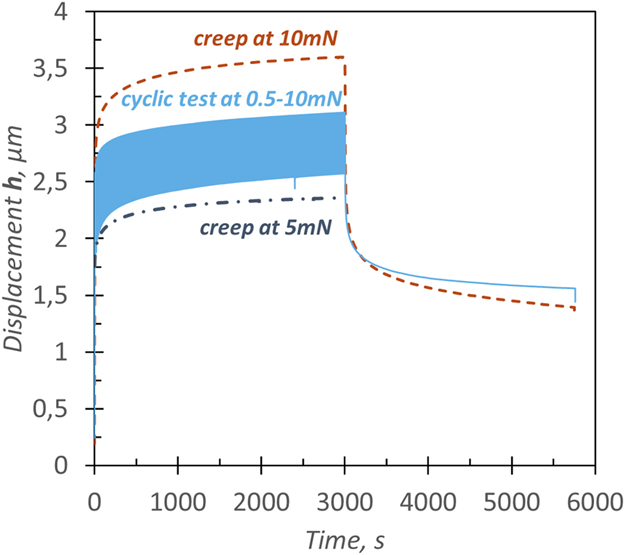
The displacement evolution with time in the cyclic indentation test at 9.6 s/cyc and two indentation creep tests, at 5 and 10 mN, on the HDPE polymer are shown in Fig. 6. One can notice that, similar to the macroscopic ratcheting, the mean displacement evolution is different in indentation cyclic test from both creep at the maximum load and creep at the mean load. This difference is quantified through a simple spring and dashpot viscoelastic model presented in Zhang et al. [Reference Zhang, Zhang, Zeng and Shen22], which fitted well the results of indentation creep test on several polymers. This model results in the following equation for displacement h as a function of time t
 $$h = {h_0} + \mathop \sum \limits_{i = 1}^n {h_i}\left( {1 - \exp \left( {{{ - t} / {{\tau _i}}}} \right)} \right) + {t \over {{\mu _0}}}\quad ,$$
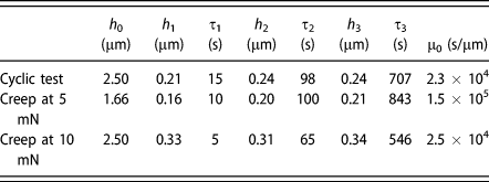
where h 0 describes instantaneous displacement after the loading, h i and τi correspond to amplitude and retardation time of each of n terms, and µ0 is a viscous flow constant. The results of this fitting with three viscoelastic terms to describe three time decades are presented in Table I. These numbers reveal that at short times, none of creep tests can describe the mean displacement evolution in cyclic test due to the time of a cycle comparable to this time-scale. At longer times, the cyclic indentation creep is close but not identical to the creep at 5 mN, corresponding to the mean load in cyclic test. However, the viscous flow is governed by the maximal load at each cycle since the µ0 coefficient is close to the one from the creep at 10 mN experiment.
Cyclic indentation test at 9.6 s/cyc and indentation creep tests at the same maximal load and a half of maximal load on HDPE.

Fitting parameters of Eq. (7) for indentation cyclic test at 9.6 s/cyc and F max = 10 mN and indentation creep tests at 5 and 10 mN on HDPE.

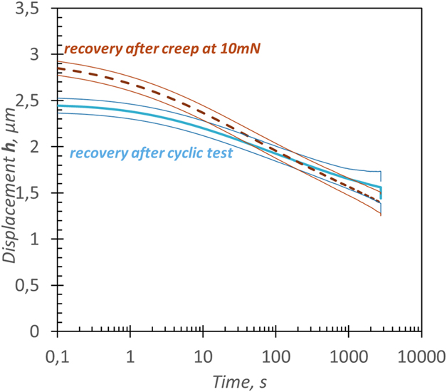
A load hold period at 0.1 mN was introduced after the unloading to study viscoelastic recovery. These recovery periods after the cyclic indentation test and creep indentation test at 10 mN are presented in Fig. 7 with a time axis starting just after the unloading to 0.1 mN. It is noteworthy that the viscoelastic recovery is slower after the indentation cyclic test than after the creep test at 10 mN. This can be explained by a different state of local equilibrium reached after both tests: while the macromolecular network had time to partially recover after each cycle, in the indentation creep test, the flow was continuous during the whole test. Unfortunately, due to instrument limitations it was not possible to conclude if the final recovery was complete and similar in two tests. It is likely, however, that a residual plastic deformation due to very high local stresses in the vicinity of contact will stay after the recovery.
Viscoelastic recovery after indentation cyclic test of 9.6 s/cyc and indentation creep test at 10 mN on HDPE. The upper and lower bounds represent variability between 9 tests.

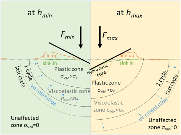
Based on the experimental observations presented above, the stress field under cyclic loading equivalent to viscoelastic–plastic behavior is schematized in Fig. 8. It is based on the cavitation model of Johnson [Reference Sills, Overney, Bhushan and Fuchs28] for elasto-plastic materials and the elastic–viscoelastic–plastic indentation field proposed by Oliveira et al. [Reference Oliveira, Costa, Teixeira and Costa5]. Both pile-up and sink-in scenarios are presented in this figure since current literature supports that the occurrence of one or the other is not directly related to viscoelastic behavior of the polymer [Reference Sills, Overney, Bhushan and Fuchs28]. The shape of the polymer surface around the contact changes with time due to viscoelastic processes underneath the surface, but the plastic zone, i.e., permanently deformed polymer chains or damaged crystals in semi-crystalline polymer, is formed during the first loading and is unaffected by unloading and further cycling. The material straight below the contact is under hydrostatic pressure equal to mean contact pressure. The stress decreases progressively with the distance from the contact, and when it goes below the yield, the deformations become viscoelastic, i.e., reversible and time dependent. The stress continues to decrease in the viscoelastic zone until the zero value in the unaffected material. This viscoelastic zone is constantly in expansion or contraction during cycling, but these processes are not in phase with the increase or decrease in the load. The delay in the retardation and relaxation deformation after the loading and unloading, respectively, results in ratcheting behavior. The relations between retardation rate and loading rate, and between relaxation rate and unloading rate, define if the maximal and minimal displacements increase with cycles, respectively. When the indenter is completely unloaded, the polymer chains continue to recover up to a certain level where only plastic deformation remains.
Schematic distribution of Von Mises stress under the indenter at maximal displacement (on the right) and minimal displacement (on the left) with pile-up and sink-in scenarios.

Conclusions
A new cyclic indentation method well-suited for polymers has been presented in this paper. This method enables to tackle time dependency by assessing the evolutions of instantaneous elastic modulus, the dissipative behavior, and ratcheting of polymers. The short time scale is covered by the instantaneous elastic modulus, the energy dissipation describes the time scale of one cycle, and the evolution of these parameters characterizes the time dependency at the time scale of the whole test. The method was tested on thermoset, amorphous thermoplastic, and semi-crystalline polymers and revealed the results consistent with viscoelastic–plastic behavior. It was shown that the evaluation of instantaneous elastic modulus from reloading rather than from unloading curve is less prone to errors for polymers. The reloading behavior of three tested polymers under three loading rates was close to the flat punch condition, implying constant contact area during reloading. The energy analysis revealed a change of tendency from the first to other cycles, which is attributed to the change of dissipative mechanisms from plastic to viscoelastic. The simplicity of the energy analysis and the absence of underlying assumptions suggest its regular use in the characterization of polymers by instrumented indentation.
Furthermore, this work showed that the indentation cyclic behavior is similar to macroscopic tension behavior. To this extent, the indentation cyclic method might replace macroscopic cyclic tests if the material is rare or expensive. Moreover, the local cyclic behavior of a heterogeneous material can be studied with the cyclic indentation test to better understand and model its macroscopic response.
Although the developed analysis method provides several indicators of polymer constitutive behavior at different time scales, a quantitative characterization of these aspects would require some modeling, which is our intention for the future work.
Materials and equipment
Materials
Three polymers used in this study are the PR520 epoxy from Cycom, the high-density polyethylene (HDPE) PE100, and the poly(methyl methacrylate) (PMMA) from GoodFellow. The HDPE sample was cut from a 1-cm-thick pipe in radial direction to obtain a 3-mm-thick sample with 1 by 2 cm sides. The glass transition temperature of −116 °C and crystallinity of 61% of the HDPE were measured by differential scanning calorimetry (DSC) with a ramp of 10 °C/min [Reference Nguyen29]. A DMA frequency sweep test in tension revealed a slight evolution of the storage elastic modulus from 1.58 GPa at 1 Hz to 1.65 GPa at 60 Hz at the temperature of 20 °C [Reference Nguyen29]. A classical stress relieving treatment was conducted on the HDPE sample at a temperature below its glass transition. The Cycom PR520 epoxy resin was moulded in a 1-cm-thick plate and cut perpendicularly to its surface to obtain 3-mm-thick 1 cm by 2 cm samples. The DSC of PR520 epoxy with a ramp of 10 °C/min provided a glass transition temperature of 146 °C and confirmed the complete curing. The manufacturer’s datasheet gives tensile strength of 82.1 MPa and tensile modulus of 4 GPa, compressive strength of 128 MPa, and compressive modulus of 3.7 GPa. The PMMA sample was bought from GoodFellow in a form of 3-mm-thick plate and used directly. According to the manufacturer, its tensile modulus is 2.4–3.3 GPa and its tensile strength is around 80 MPa. The epoxy and PMMA materials were not subjected to any thermal treatment prior to indentation tests.
Equipment and corrections
This study was carried out on Fischerscope H100C (Helmut Fischer GmbH, Sindelfingen, Germany) ultra-microindenter equipped with a Vickers diamond tip. This equipment allows to perform force-controlled tests in a range between 0.1 and 1000 mN with an uncertainty of 0.02 mN. The maximal measurable depth is 700 µm, and the uncertainty on the displacement values is 2 nm. During the tests, load and displacement data are recorded every 0.1 s. The area function and frame compliance were calibrated through standard procedure. The surface roughness of all samples was minimized by a careful polishing up to R a = 1.3 nm, and the surface tilt was verified to be less than 1°.
The minimum and maximum loads for cycles were 0.5 and 10 mN. The load hold at the end of test to evaluate material recovery was performed at 0.1 mN. The number of cycles varied between 20 and 1200 for different tests described here and was limited by the 6000 s of maximum time recording allowed by the equipment. Since some of cyclic tests were very long, a particular attention was paid to a drift which origin is not in material behavior, commonly called thermal drift. This drift is explained by small environmental variations of temperature and electromagnetic heating of the indenter actuator, which cause small, but significant on the scale of test, displacements of the indenter tip. These displacements interfere with the sample response and need to be corrected to obtain material properties properly. It is common to evaluate thermal drift by introducing a hold period at a very low load, before the loading. This displacement–time data should be fitted with a linear law and the slope correction coefficient is propagated to the whole indentation data. Although this procedure is commonly adapted, some authors suggest to imply other procedures of thermal drift correction which provide better results. For instance, Chattaraj et al. [Reference Chattaraj, Pant and Nanavati9] used “quadratic correction method” based on holding periods before and after the experiment, which are fitted separately with a linear law. The slopes of these curves are combined in a quadratic equation, which is used to correct all data.
In our opinion, since the thermal drift nature depends on interaction between the equipment components, local environment, and the sample, the correction method is not universal and should be adapted in each case for the best reduction in the scatter of measured displacements. With polymers, the challenge is to separate the instrument drift from the time-dependent response of material. If the holding period is introduced at the beginning of the test, it might be affected by polymer creep, but at the end of the test it would be affected by the recovery. In this work, a holding period was introduced at the beginning of the test and a low load was chosen to avoid significant creep behavior. A careful study was conducted on different materials (polymers and others) to choose the load level, the duration of the holding period, and the fitting function of time–displacement data to be used for thermal drift evaluation. The choice was the best compromise between the reduction in the standard deviation among the results and the applicability to a large range of tests of different durations. The load value retained is 0.1 mN and the duration is 600 s. It has been observed that the use of a power law fitting instead of a linear fitting of displacement–time data during holding results in a better correction for the longer tests. This reduction in variation was observed on long holding tests, i.e., indentation creep tests, but also on cyclic tests. For instance, this correction results in a standard deviation of 0.05 µm from 9 tests around the mean value of 3.83 µm at the end of a creep test of 6000 s at 10 mN on the HDPE. An example of the effect of thermal drift correction is given in the Supplementary material.
Supplementary material
To view supplementary material for this article, please visit https://doi.org/10.1557/jmr.2019.289.
Acknowledgments
The authors would like to acknowledge the Poitou-Charentes region for financing the Ph.D. scholarship of M. Pecora and the financial help of CNRS through financing PEPS INSIS MICMA project. This work pertains to the French government program “Investissements d’Avenir” LABEX INTERACTIFS (reference ANR-11-LABX-0017-01).