1 Introduction
The flow of a thin film over a rotating disk is important in numerous industrial applications such as the spinning disk reactor, spin coating, jet cooling of rotating devices, spray and atomization and powder production (Lawley Reference Lawley1992; Uma & Usha Reference Uma and Usha2009). The film thickness can be controlled and made very small by the rotation speed, providing good heat and mass transfer characteristics (Aoune & Ramshaw Reference Aoune and Ramshaw1999). Therefore, the prediction of the associated hydrodynamic features, such as the film thickness, wall shear stress and surface velocity, is crucial in the design of relevant industrial processes.
We examine the thin-film flow as a result of a circular jet impinging on a rotating disk. Similar to the flow of a jet impinging on a stationary surface, a circular hydraulic jump is expected to arise when a fluid jet falling vertically at high Reynolds number strikes a horizontal rotating disk. The fluid is expelled radially and tangentially, and the layer can thin until reaching a critical radius at which the layer depth increases abruptly. Although the impingement of a circular jet on a stationary disk has been extensively considered, the case of an impinging jet on a rotating disk with hydraulic jump formation has essentially not been examined. For a stationary surface, early predictions for the jump radius based on inviscid theory were presented by Rayleigh (Reference Rayleigh1914). Viscous effects were later considered by Tani (Reference Tani1949), but the dominant influence of fluid viscosity on the jump radius was elucidated by Watson (Reference Watson1964) who developed an appropriate description of the boundary layer that develops from the lower boundary. Watson (Reference Watson1964) studied both the radial and planar jet spreads for steady laminar and turbulent flows on a stationary solid surface. Watson’s thin-film approach became the basis for numerous theoretical and experimental studies.
In particular, the location of the hydraulic jump remain the focus of many studies. Using a similar shallow-water approach, Bohr, Dimon & Putzkaradze (Reference Bohr, Dimon and Putzkaradze1993) found that the jump radius scales approximately as
 $Q^{5/8}\unicode[STIX]{x1D708}^{-3/8}g^{-1/8}$
, where
 $Q$
is the jet flow rate,
 $\unicode[STIX]{x1D708}$
is the kinematic viscosity and
 $g$
is the acceleration sue to gravity. Brechet & Neda (Reference Brechet and Neda1999) investigated experimentally the influence of flow rate, viscosity and the nozzle-to-disk distance on the location of the hydraulic jump, and reached a scaling law similar to that proposed by Bohr et al. (Reference Bohr, Dimon and Putzkaradze1993). They also observed that the nozzle-to-disk distance has no influence on the jump location. Kasimov (Reference Kasimov2008) studied the influence of surface tension on the stability of the hydraulic jump, and found that a steady jump may not exist at high surface tension. Passandideh-Fard, Teymourtash & Khavari (Reference Passandideh-Fard, Teymourtash and Khavari2011) proposed a numerical approach to determine the hydraulic jump location. The free surface was tracked by a volume-of-fluid approach. In their calculation domain, the downstream depth was imposed at the disk edge. The influence of slip was also examined using Watson’s thin-film approach (Dressaire et al.
Reference Dressaire, Courbin, Crest and Stone2010; Prince, Maynes & Crockett Reference Prince, Maynes and Crockett2012; Khayat Reference Khayat2016). The jump location is of major fundamental significance, and will be examined extensively in this paper for stationary and rotating disks.
The location where the boundary layer reaches the free surface separates a developing boundary-layer region from a viscous boundary-layer region. The developing boundary-layer height before the separation point was determined using a Kármán–Pohlhausen approach and the similarity profile for the velocity. Downstream of the separation point, the same similarity profile was assumed to (approximately) hold. Based on the balance of forces, a relation between the jump location and the height was also obtained for both laminar and turbulent flows. Watson’s theory was tested in a number of experimental investigations, including those of Watson himself, Craik et al. (Reference Craik, Latham, Fawkes and Gibbon1981), Stevens & Webb (Reference Stevens and Webb1992), Bush & Aristoff (Reference Bush and Aristoff2003) and Baonga, Gualous & Imbert (Reference Baonga, Gualous and Imbert2006). Liu & Lienhard (Reference Liu and Lienhard1993) observed that Watson’s predictions are least satisfactory in the limit of relatively weak jump, specifically when the ratio of the layer depths down- and upstream of the jump is small. Surface tension effect was neglected in Watson’s work. In an effort to improve Watson’s theory, Bush and co-workers included the influence of surface tension for small circular jump radius, which led to a better agreement with experiment. They elucidated the influence of surface tension on the circular hydraulic jump, both its size (Bush & Aristoff Reference Bush and Aristoff2003) and stability (Bush, Aristoff & Hosoi Reference Bush, Aristoff and Hosoi2006), through combined theoretical and experimental investigations. It is, however, generally agreed that Watson’s theory is adequate for a circular jump with relatively large radius and height. Other extensions have also been considered in the recent past, such as the spread of an impinging non-Newtonian jet (Zhao & Khayat Reference Zhao and Khayat2008), formation of hydraulic jump on an inclined plane (Kate, Das & Chakraborty Reference Kate, Das and Chakraborty2007; Benilov Reference Benilov2015), the influence of slip (Dressaire et al. Reference Dressaire, Courbin, Crest and Stone2010; Prince et al. Reference Prince, Maynes and Crockett2012; Khayat Reference Khayat2016) and the influence of gravity on the jump radius for impingement on a stationary plate (Avedisian & Zhao Reference Avedisian and Zhao2000).
The axisymmetric hydraulic jump flow can become unstable, giving way to steady polygonal jumps of various shapes. Ellegaard et al. (Reference Ellegaard, Hansen, Haaning, Marcussen, Bohr, Hansen and Watanabe1998, Reference Ellegaard, Hansen, Haaning, Hansen, Marcussen, Bohr, Hansen and Watanabe1999) first demonstrated that the axisymmetry of the viscous hydraulic jump may be broken, resulting in steady polygonal jumps. Bush et al. (Reference Bush, Aristoff and Hosoi2006) have further examined these striking flow structures. They also conducted parameter studies that revealed new non-axisymmetric patterns and their dependence on the governing parameters. The polygonal regime was also examined theoretically using a thin-film approach by Martens, Watanabe & Bohr (Reference Martens, Watanabe and Bohr2012) and numerical simulation by Rojas & Tirapegui (Reference Rojas and Tirapegui2015). Recent experimental work was reported by Teymourtash & Mokhlesi (Reference Teymourtash and Mokhlesi2015).
Regarding the influence of rotation, extensive work was done on the flow of a thin film and wave formation. Again, little is reported on hydraulic jump formation. The film thickness was the main focus in experiments using mechanical, optical or electrical techniques. The early film thickness measurements of Charwat, Kelly & Gazley (Reference Charwat, Kelly and Gazley1972) involved an infrared-adsorption technique for water and other solutions on a rotating disk. They found that the film thickness
 $\bar{h}$
decays with rotation speed
 $\unicode[STIX]{x1D714}$
and radial distance
 $\bar{r}$
like
 $\bar{h}\sim \bar{r}^{-1}(Q\unicode[STIX]{x1D708}/\unicode[STIX]{x1D714}^{2})^{2/5}$
. Meanwhile, for comparison, when the Coriolis force is dominant over inertia, the balance between the centrifugal and viscous terms in the radial momentum equation yields
 $\bar{h}\sim \bar{r}^{-2/3}(Q\unicode[STIX]{x1D708}/\unicode[STIX]{x1D714}^{2})^{1/3}$
, which also corresponds to the asymptotic form obtained by Rauscher, Kelly & Cole (Reference Rauscher, Kelly and Cole1973). As observed in their experiment, this asymptotic relation also reflects a decrease in the film thickness with rotation speed and radial distance. However, the measurements indicate a stronger drop of the film thickness with both rotation speed and distance. Miyasaka (Reference Miyasaka1974) measured the thickness of a thin viscous liquid film on a rotating disk for a liquid jet falling onto the centre of the disk. The focus was on the inner region close to the centre. The film height was deduced from the electrical resistance of the liquid on the disk and compared with the electrical resistance of a standard thickness of the fluid. Their theory was found to agree with experiment. Potential flow was assumed to exist in the azimuthal direction. Thomas et al. (Reference Thomas, Hankey, Faghri and Swanson1990) performed a one-dimensional analysis of the film thickness, including the hydraulic jump. They predicted significant thinning of the film with increased speed of rotation. The hydraulic jump was found to ‘wash out’ at a high speed of rotation, and was shown not to exist at all in the absence of gravity.
The hydraulic jump was also observed by Thomas, Faghri & Hankey (Reference Thomas, Faghri and Hankey1991), who conducted thickness measurements of a film emerging from a collar on a rotating disk. The jump location was found to depend on the rotation speed and the flow rate. They identified three distinct flow regions: an inner inertia-dominated region close to the centre of the disk, a transition region, and an outer rotation-dominated region. Rahman & Faghri (Reference Rahman and Faghri1992) investigated numerically the hydrodynamic behaviour of a thin liquid film flowing over a rotating disk. A three-dimensional boundary-fitted coordinate system was used to perform the calculations. The computed film thickness agreed well with existing experimental measurements. It was also concluded that the flow was dominated by inertia near the entrance and by centrifugal force near the outer edge of the disk. More recently, Burns, Ramshaw & Jachuck (Reference Burns, Ramshaw and Jachuck2003) measured the film thickness on a rotating disk as being inversely proportional to the electric resistance. The thickness was measured for four different liquids, and was found to be smaller by approximately 10 % than the asymptotic prediction of Rauscher et al. (Reference Rauscher, Kelly and Cole1973). We shall assess these observations against our own findings in the current study.
Surface waves of axisymmetric and non-axisymmetric shapes can form depending on the flow rate and rotation speed. Charwat et al. (Reference Charwat, Kelly and Gazley1972) found that smooth flow occurs in a region defined by the flow rate, rotational speed and physical properties of the liquid. Outside this region various wave patterns were observed (concentric, spiral and irregular waves). A linear stability analysis of the film was given and contrasted with the experimental results. Apparent surface tension associated with the use of wetting agents were found to have a strong effect on the stability of the film. Sisoev, Matar & Lawrence (Reference Sisoev, Matar and Lawrence2003) developed a system of nonlinear evolution equations to model axisymmetric capillary waves in film flow over a spinning disk. Approximate solutions in the form of regular waves (periodic waves travelling with constant velocity) have been investigated. Computed solutions with measured wave shapes have led qualitative and quantitative agreements. Later Matar, Sisoev & Lawrence (Reference Matar, Sisoev and Lawrence2004) studied the spatio-temporal development of a thin viscous film flowing over a spinning disk. Using the Kármán–Pohlhausen method with an assumed parabolic profile for the film velocity, the nonlinear evolution of the thin viscous film was investigated using the model proposed in their former study. Their results revealed a typical film wave evolution in the presence of an appreciable inertial contribution which acts to destabilize the flow. For studies involving non-axisymmetric wave and more investigations related to wave formation, the reader is referred to the work of Sisoev, Goldgof & Korzhova (Reference Sisoev, Goldgof and Korzhova2010) and the references therein.
Of closer relevance to the present problem is the experimental study of Ozar, Cetegen & Faghri (Reference Ozar, Cetegen and Faghri2003), who examined the radial spread of water emerging from a collar onto the surface of a rotating disk. The film thickness was found to vary with the flow rate as well as the rotation speed. The location of the hydraulic jump was found to increase with the flow rate as well as the rotation rate, and could be washed off the disk surface at large rotation rate. In addition, a local maximum in the film thickness was observed in their experiments when the hydraulic jump vanishes. Later, Rice, Faghri & Cetegen (Reference Rice, Faghri and Cetegen2005) examined numerically the same problem (the flow of a thin film emerging from a collar over a rotating disk). Their computations were run on a two-dimensional axisymmetric Eulerian mesh, and the film thickness was determined using the volume-of-fluid method. The film thickness was obtained under different temperatures. Their results agreed qualitatively with the measurements of Ozar et al. (Reference Ozar, Cetegen and Faghri2003), as the film thickness was found to decrease with increasing rotation speed. They did not consider the formation of a hydraulic jump. In addition, in contrast to the current impinging jet flow problem, the film height must be given at some upstream location, presumably corresponding to the distance between the collar and the disk surface.
An approximate approach was developed by Basu & Cetegen (Reference Basu and Cetegen2007), who investigated the thin-film flow on a rotating disk using an integral method, and adopting a parabolic profile for the radial velocity component. At low film inertia and low rotation rate, a hydraulic jump was predicted on the disk surface. By scaling analysis, the film thickness was found to be in reasonably good agreement with the numerical results of Rice et al. (Reference Rice, Faghri and Cetegen2005) as well as the measurements of Ozar et al. (Reference Ozar, Cetegen and Faghri2003). Comparison for the location and height of the hydraulic jump was not reported. Moreover, their parabolic profile is relatively inaccurate as it does not satisfy the momentum equation at the disk surface. Finally, Deng & Ouyang (Reference Deng and Ouyang2011) studied the vibration of spinning disks and the powder formation in centrifugal atomization, focusing on the vibration of the atomizing disk excited by a moving melt. The hydraulic jump was predicted in their study, but no information on its location was reported.
An outstanding issue plaguing the analysis of the hydraulic jump on a stationary or rotating disk is how to uniquely determine the location and height of the jump. The recent measurements of Duchesne, Lebon & Limat (Reference Duchesne, Lebon and Limat2014) show that, for a stationary disk, the Froude number, based on the jump height and velocity, remains constant when the flow rate, viscosity and surface tension are varied. Photographs of the transition across the jump from submerged views have been reported (Avedisian & Zhao (Reference Avedisian and Zhao2000)), which illustrate the challenges of identifying the jump location on a stationary surface when the height changes gradually from upstream to downstream on a sudden reduction of gravity. The constancy of the subcritical Froude number suggested by Duchesne et al. (Reference Duchesne, Lebon and Limat2014) should in principle provide the desired relation for problem completion. However, no theoretical justification was provided. More recently, the measurements of Mohajer & Li (Reference Mohajer and Li2015) do indeed support the claim of Duchesne et al. (Reference Duchesne, Lebon and Limat2014), but found that the Froude number is not independent of the surface tension. We shall revisit this issue and provide some theoretical arguments and comparison with experiment.
The current study explores the interplay between inertia and rotation for a thin film flowing on a rotating disk as a result of jet impingement. Since axisymmetric flow is examined, the surface-tension effect will be included. In § 2, we outline the problem formulation by giving the governing equations and boundary conditions in each region. The overall solution strategy is also discussed. In § 3, the Kármán–Pohlhausen (K–P) approach is adopted to determine the boundary-layer structure and the film thickness upstream of the jump. The transition point is also located. In § 4, the K–P approach is employed again to examine the viscous boundary-layer region, and assess the influence of rotation on the thin-film flow. In § 5, the location of the hydraulic jump is determined by a momentum balance across the jump, and the effect of rotation on the jump is analysed. The case of the flow on a stationary disk is revisited to establish the value of the film thickness at the edge of the disk, and we extend the argument for a rotating disk. Finally, concluding remarks are given in § 5.
2 Physical domain and problem statement
Consider the steady laminar incompressible flow of a circular axisymmetric jet of a Newtonian fluid of radius
 $a$
, impinging at a volume flow rate
 $Q$
on a flat disk lying normal to the jet direction and rotating at an angular velocity
 $\unicode[STIX]{x1D714}$
. The flow configuration is depicted schematically in figure 1, where dimensionless variables and parameters are used. The problem is formulated in the
 $(r,\unicode[STIX]{x1D703},z)$
fixed coordinates, with the origin coinciding with the disk centre. In this case,
 $u(r,z)$
,
 $v(r,z)$
and
 $w(r,z)$
are the corresponding dimensionless velocity components in the radial, azimuthal and vertical directions, respectively. The
 $r$
-axis is taken along the disk radius and the
 $z$
-axis is taken parallel to the jet. Since the flow is assumed to be axisymmetric, there is no dependence on the azimuthal angle
 $\unicode[STIX]{x1D703}$
. The length and velocity scales are conveniently taken to be
 $a$
and
 $Q/\unicode[STIX]{x03C0}a^{2}$
in the radial, azimuthal and vertical directions. A more suitable scaling is used in the appendix where the thin-film problem is formulated. Since the pressure is expected to be predominantly hydrostatic for a thin film, it will be scaled by
 $\unicode[STIX]{x1D70C}ga$
. Four dimensionless groups emerge in this case: the Reynolds number
 $Re=(Q/\unicode[STIX]{x03C0}a\unicode[STIX]{x1D708})$
, where
 $\unicode[STIX]{x1D708}$
is the kinematic viscosity, the rotation parameter,
 $\unicode[STIX]{x1D6FA}=(\unicode[STIX]{x03C0}a^{3}\unicode[STIX]{x1D714}/Q)$
, the Froude number,
 $Fr=(Q/\unicode[STIX]{x03C0}\sqrt{a^{5}g})$
,
 $g$
being the acceleration due to gravity and the Bond number,
 $Bo=(\unicode[STIX]{x1D70C}ga^{2}/\unicode[STIX]{x1D6FE})$
,
 $\unicode[STIX]{x1D70C}$
being the density. We note that
 $\unicode[STIX]{x1D6FA}^{-1}$
may be introduced as the Rossby number. Another group number that is independent of the flow rate:
 $G\equiv Re/Fr^{2}$
is useful to introduce, which reflects the effect of gravity relative to inertia.
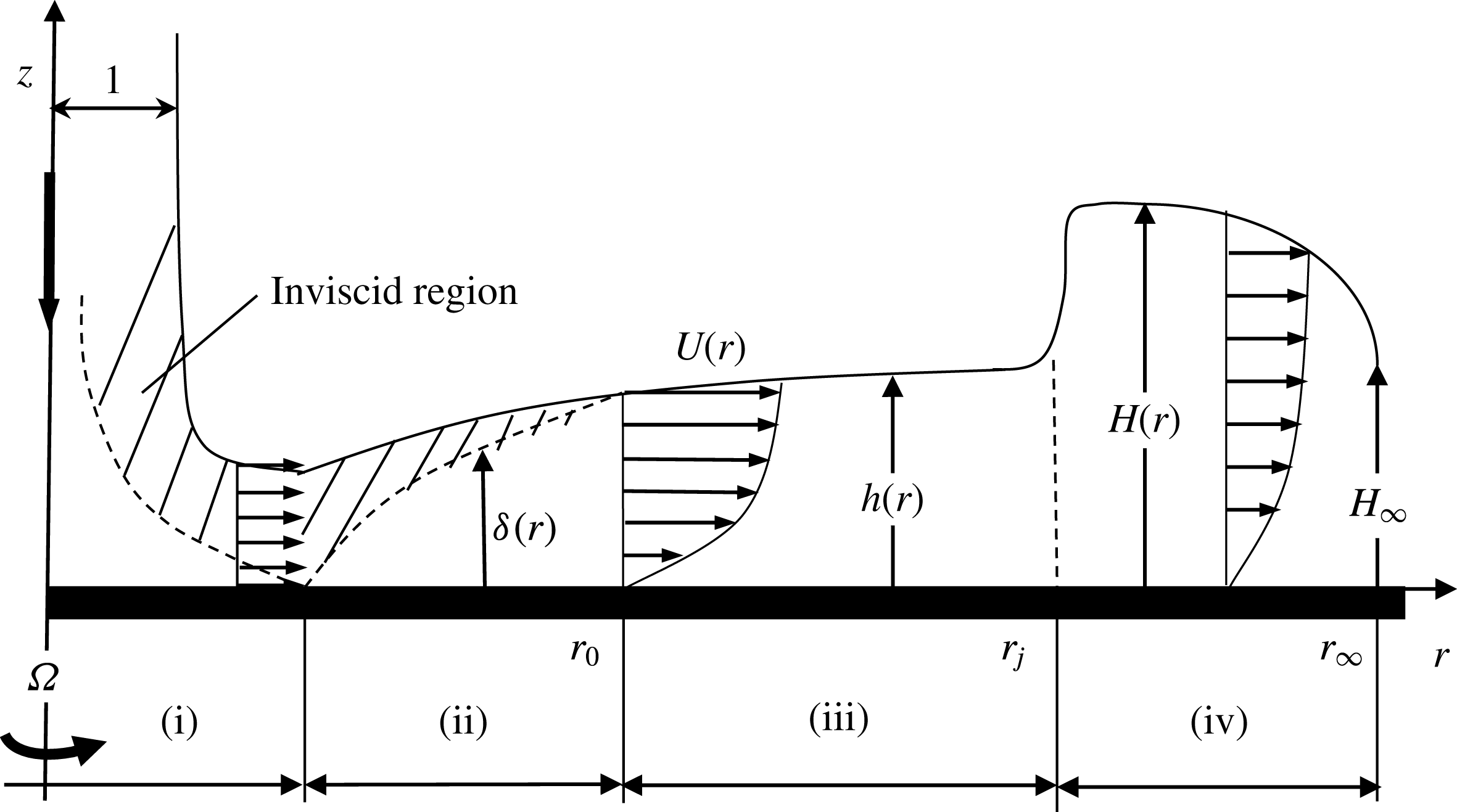
Schematic illustration of the axisymmetric jet flow impinging on a flat rotating disk. Illustrated are the stagnation region (i), the developing boundary-layer region (ii), the fully viscous region (iii) and the hydraulic jump region (iv). All notations are dimensionless.

In this study, the flow is assumed to remain steady and axisymmetric. Therefore, surface waves that may be present on the liquid film under some conditions are not accounted for. When the flow rate or rotation speed is relatively small, or the apparent surface tension of a liquid is below a critical value, the flow is smooth and axisymmetric without any sign of wave (Charwat et al.
Reference Charwat, Kelly and Gazley1972). Otherwise, surface waves of axisymmetric and non-axisymmetric shapes can be present, depending on flow rate and rotation speed. Charwat et al. (Reference Charwat, Kelly and Gazley1972) carried out experimental measurements and linear stability analysis for a thin film formed on a rotating disk. Smooth flow was found to occur in a region defined by the flow rate, rotational speed and physical properties of the liquid. Outside this region various wave patterns were observed: concentric, spiral and irregular waves. In their experiments with water and glycerine solution, Butuzov & Pukhovoi (Reference Butuzov and Pukhovoi1976) observed that a laminar film with no signs of wave formation is possible over the entire disk for angular velocities below 400 rpm and low flow rates. The second situation corresponds to a flow with low surface tension. In their experiment, Charwat et al. (Reference Charwat, Kelly and Gazley1972) observed that for a fluid with surface tension coefficient less than approximately
 $57~\text{dyn}~\text{cm}^{-1}$
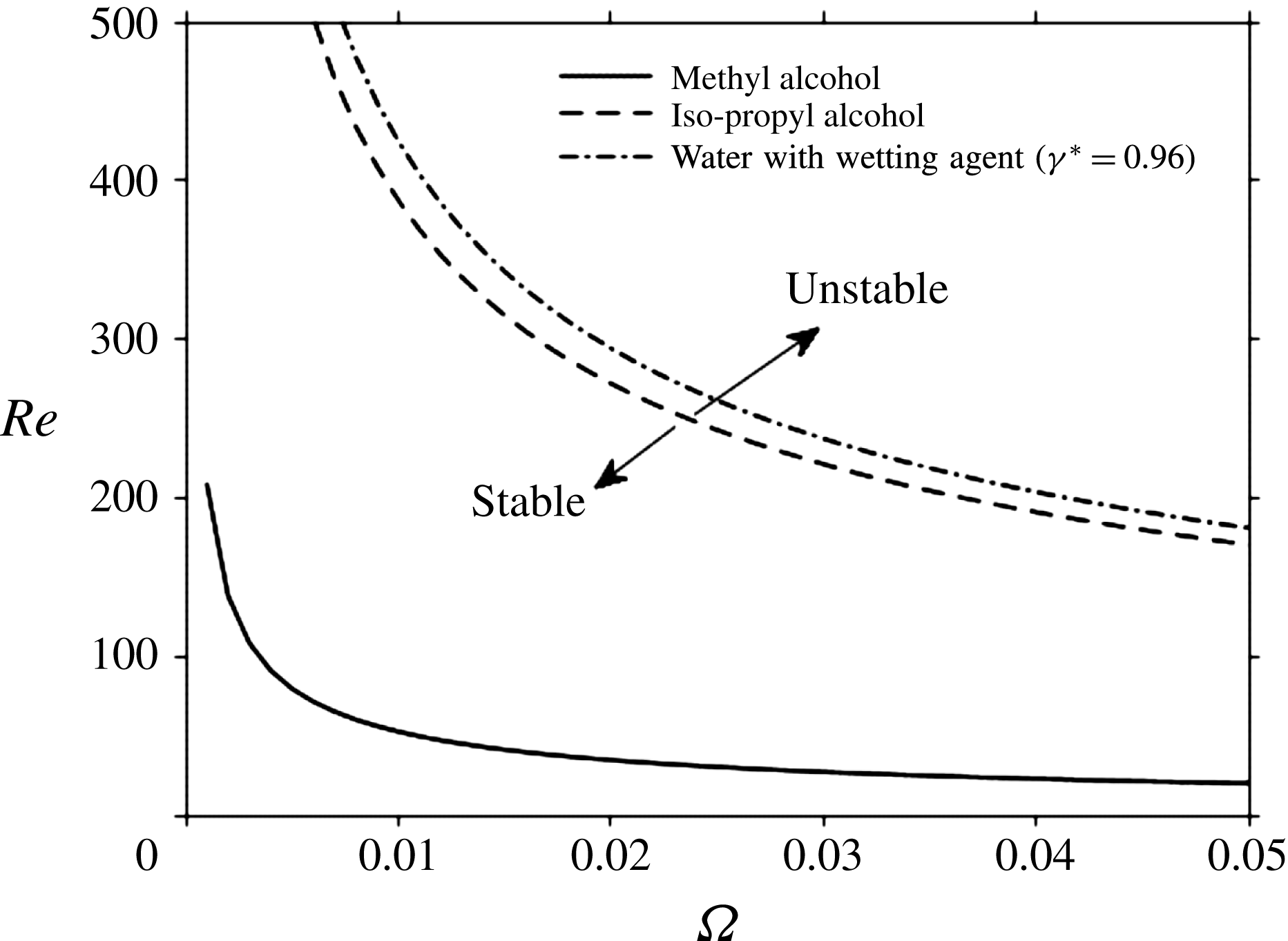
, the film becomes absolutely stable, with no waves of any kind observed throughout the entire range of flow rates and rotational speeds covered. Figure 2 depicts the marginal stability curves, reproduced from Charwat et al. (Reference Charwat, Kelly and Gazley1972) in the
 $(Re,\unicode[STIX]{x1D6FA})$
plane for three liquids: methyl alcohol, iso-propyl alcohol and water with a wetting agent. The region of stable axisymmetric flow lies below each curve while the region for the onset of spiral waves lies above. Clearly, axisymmetric flow is predicted over a wide range of Reynolds number and rotation speed. This range widens for liquids with lesser surface tension, which seem to exhibit wavy flow only if
 $Re$
is of order
 $10^{3}$
. The current calculations for the flow over a rotating disk are essentially limited to
 $Re<600$
and
 $\unicode[STIX]{x1D6FA}\ll 1$
(see figures 9–11), which ensures the validity of the assumption of flow axisymmetry.
Marginal stability curves based on the analysis of Charwat et al. (Reference Charwat, Kelly and Gazley1972) reproduced here in the
 $(Re,\unicode[STIX]{x1D6FA})$
plane. The stable (unstable) region below (above) each curve that corresponds to axisymmetric (wavy) flow is indicated here for iso-propyl alcohol.

2.1 The physical domain
Following the treatment of Watson (Reference Watson1964) of the flow over a stationary disk, we identify four distinct flow regions for the jet over a rotating disk, with smooth passage from one region to the next (see figure 1): a stagnation flow region (i), a developing boundary-layer region (ii), where the boundary layer grows until it reaches the film surface at
 $r=r_{0}$
, and a fully viscous thin-film region (iii). Under some flow conditions, a hydraulic jump may form in region (iv), starting at
 $r=r_{j}$
. In the vicinity of the stagnation point, in region (i),
 $r=O(1)$
. The velocity outside the boundary layer rises rapidly from 0 at the stagnation point to the impingement velocity in the inviscid far region. In region (ii), the boundary layer is expected to grow like
 $\sqrt{r/Re}$
, at a rate that diminishes with
 $\unicode[STIX]{x1D6FA}$
. The elongation rate or normal stress weakens with distance, but the flow remains axisymmetric (as opposed to becoming almost planar) with non-negligible surface curvature. The speed outside the boundary layer remains almost constant, equal to 1 (in units of
 $Q/\unicode[STIX]{x03C0}a^{2}$
), as the fluid here is unaffected by the viscous stresses. For
 $r\gg 1$
, the flow field in region (ii) is not significantly affected by the stagnation flow of region (i). The region
 $1\ll r<r_{0}$
will be referred to as the developing boundary-layer region, with boundary-layer thickness
 $\unicode[STIX]{x1D6FF}(r)$
, outside which the flow is inviscid and constant. Here
 $r_{0}$
is the location of the transition point at which viscous stresses become appreciable right up to the free surface, where the whole flow is of the boundary-layer type. At this point, the velocity profile changes from the Blasius type to the similarity profile for a stationary disk. In contrast, a similarity profile does not exist for a jet impinging on a rotating disk. The flow in region (iii),
 $r>r_{0}$
, which will be referred to as the fully developed viscous region, is bounded by the disk and the free surface
 $z=h(r)$
.
Finally, the hydraulic jump in region (iv) occurs at a location
 $r=r_{j}$
, which can be larger or smaller than
 $r_{0}$
since the jump may occur at any point in the flow. It is convenient to introduce the (supercritical) film thickness upstream of the jump as
 $h(r)=h(r<r_{j})$
and the (subcritical) thickness downstream of the jump as
 $H(r)\equiv h(r>r_{j})$
. The jump height
 $H(r)$
is generally not constant but is different from the height immediately downstream of the jump,
 $H_{j}=H(r=r_{j})$
. In this study, the fluid is assumed to be drained at the edge of the disk
 $r=r_{\infty }$
to maintain steady flow, with the film thickness denoted by
 $H_{\infty }=H(r=r_{\infty })$
. Although it is common practice to assume the jump height to remain equal to
 $H_{j}$
, this assumption is valid for fluids of low viscosity on a stationary disk. The edge thickness is expected to depend heavily on the rotation speed and surface tension, but not so much on the flow rate (Mohajer & Li Reference Mohajer and Li2015). In this study, we consider a viscous layer downstream of the jump.
2.2 Governing equations and boundary conditions
Unless otherwise specified, the Reynolds number is assumed to be moderately large so that our analysis is confined to the laminar regime. Consequently, for steady axisymmetric thin-film flow, in the presence of rotation, the mass and momentum conservation equations are formulated using a thin-film or Prandtl boundary-layer approach, which amounts to assuming that the radial flow varies much slower than the vertical flow (Schlichtling Reference Schlichtling2000). The thin-film problem is formulated in the appendix. By letting a subscript with respect to
 $r$
or
 $z$
denote partial differentiation, the reduced dimensionless conservation equations become
 $$\begin{eqnarray}\displaystyle & \displaystyle u_{r}+{\displaystyle \frac{u}{r}}+w_{z}=0, & \displaystyle\end{eqnarray}$$
 $$\begin{eqnarray}\displaystyle & \displaystyle Re\left(uu_{r}+wu_{z}-{\displaystyle \frac{v^{2}}{r}}\right)=-{\displaystyle \frac{Re}{Fr^{2}}}p_{r}+u_{zz}, & \displaystyle\end{eqnarray}$$
 $$\begin{eqnarray}\displaystyle & \displaystyle Re\left(uv_{r}+wv_{z}+{\displaystyle \frac{uv}{r}}\right)=v_{zz}, & \displaystyle\end{eqnarray}$$
 $$\begin{eqnarray}\displaystyle & \displaystyle p_{z}=\left\{\begin{array}{@{}ll@{}}0\quad & r<r_{j}\\ -1\quad & r>r_{j}.\end{array}\right. & \displaystyle\end{eqnarray}$$
These equations are essentially the same as those used by Bohr et al. (Reference Bohr, Ellegaard, Hansen and Haaning1996). We observe that the pressure for a thin film is essentially hydrostatic as a result of its vanishing at the film surface (in the absence of surface tension) and the small thickness of the film. In addition, upstream of the jump, the variation of the film thickness with the radius is expected to be smooth and gradual. In this case, the radial variation of the hydrostatic pressure is also small. According to the calculations of Prince et al. (Reference Prince, Maynes and Crockett2012), the hydrostatic pressure exerts less than 0.4 % cumulative influence on the dynamics of the thin film, and is thus neglected upstream of the hydraulic jump. This is generally commonly assumed in modelling hydraulic jump flow, where the hydrostatic pressure is included only downstream of the jump where the film is relatively thicker (Watson Reference Watson1964; Bush & Aristoff Reference Bush and Aristoff2003; Dressaire et al.
Reference Dressaire, Courbin, Crest and Stone2010; Prince et al.
Reference Prince, Maynes and Crockett2012). At the disk, the no-slip and no-penetration conditions are assumed to hold for any
 $r$
. In this case:
 $$\begin{eqnarray}u(r,z=0)=0,\quad v(r,z=0)=\unicode[STIX]{x1D6FA}r,\quad w(r,z=0)=0.\end{eqnarray}$$
At the free surface
 $z=h(r<r_{j})$
or
 $z=H(r>r_{j})$
, the kinematic condition for steady flow takes the form
 $$\begin{eqnarray}w(r,z=h)=u(r,z=h)h^{\prime }(r).\end{eqnarray}$$
Here a prime denotes total differentiation. In addition, the radial and tangential shear stress components as well as the pressure must vanish everywhere
 $(0<r<r_{\infty })$
, so that
 $$\begin{eqnarray}u_{z}(r,z=h)=v_{z}(r,z=h)=p(r,z=h)=0.\end{eqnarray}$$
The flow field is sought separately in the developing boundary-layer region (ii) for
 $0<r<r_{0}$
, the fully developed viscous boundary-layer region (iii) for
 $r_{0}<r<r_{j}$
and the hydraulic jump region (iv) for
 $r_{j}<r<r_{\infty }$
. We observe that region (i) is negligible, and the leading edge of the boundary layer in region (ii) coincides with the disk centre (see § 2.3). Consequently, the additional boundary conditions are as follows. In region (ii), the flow is assumed to be sufficiently inertial for inviscid flow to prevail between the boundary-layer outer edge and the free surface (see figure 1). In this case, the following condition at the outer edge of the boundary layer and beyond must hold:
 $$\begin{eqnarray}u(r<r_{0},z=\unicode[STIX]{x1D6FF})=1,\quad u_{z}(r<r_{0},z=\unicode[STIX]{x1D6FF})=0,\quad u(r<r_{0},\unicode[STIX]{x1D6FF}\leqslant z<h)=1.\end{eqnarray}$$
Integrating equation (2.1d ) subject to condition (2.4c ), the pressure becomes
 $$\begin{eqnarray}p(r,z)=\left\{\begin{array}{@{}ll@{}}0\quad & r<r_{j}\\ H(r)-z\quad & r\geqslant r_{j}.\end{array}\right.\end{eqnarray}$$
Equations (2.1b ) and (2.1c ) must be satisfied at the rotating disk. Thus, we have
 $$\begin{eqnarray}\displaystyle & \displaystyle u_{zz}(r,z=0)=-Re\unicode[STIX]{x1D6FA}^{2}r+\left\{\begin{array}{@{}ll@{}}0\quad & r<r_{j}\\ G{\displaystyle \frac{\text{d}H}{\text{d}r}}\quad & r>r_{j},\end{array}\right. & \displaystyle\end{eqnarray}$$
 $$\begin{eqnarray}\displaystyle & \displaystyle v_{zz}(r,z=0)=0, & \displaystyle\end{eqnarray}$$
 $u(r,z)$
and
 $w(r,z)$
, and subject to conditions (2.2b
), (2.4b
) and (2.7b
), equation (2.1c
) admits the following exact solution for the tangential velocity component:
 $$\begin{eqnarray}v(r,z)=\unicode[STIX]{x1D6FA}r.\end{eqnarray}$$
This simple behaviour is not unexpected for a thin film flowing with a free surface and adhering to the rotating disk. We note that (2.8) holds throughout the flow domain. Finally, the conservation of mass at any location upstream and downstream of the jump yields the following relation in dimensionless form:
 $$\begin{eqnarray}{\displaystyle \frac{1}{2r}}=\int _{0}^{h(r)}u(r<r_{j},z)\,\,\text{d}z=\int _{0}^{H(r)}u(r>r_{j},z)\,\,\text{d}z.\end{eqnarray}$$
We note that this relation follows from the mass conservation relation in dimensional form:
 $Q=2\unicode[STIX]{x03C0}\bar{r}\int _{0}^{\bar{h}(\bar{r})}\bar{u}(\bar{r},\bar{z})\,\text{d}\bar{z}$
, where a barred variable denotes a dimensional quantity.
2.3 Overall solution strategy
Throughout this study, the stagnation region (i) under the impinging jet is assumed to be negligibly small. The velocity outside the boundary layer rises rapidly from 0 at the stagnation point to the impingement velocity in the inviscid far region. For a jet on a stationary as well as a rotating disk, the impinging jet is predominantly inviscid close to the stagnation point, and the boundary-layer thickness remains negligibly small. Obviously, this is the case for a jet at relatively large Reynolds number. Disk rotation adds to the inviscid character of the flow upon impingement. Ideally, the flow at the boundary-layer edge should correspond to the (almost parabolic) potential flow near the stagnating jet, with the boundary-layer leading edge coinciding with the stagnation point (Liu, Gabour & Lienhard Reference Liu, Gabour and Lienhard1993). However, the assumption of uniform horizontal flow near the wall and outside the boundary layer (as illustrated in figure 1) is reasonable. The distance from the stagnation point for the inviscid flow to reach uniform horizontal velocity is small, of the order of the jet radius (Lienhard Reference Lienhard2006). In addition, for a jet on a stationary disk, the flow acquires a similarity character. In this case, the position or effect of the leading edge is irrelevant. This is not the case for the current jet on a rotating disk, where, as we shall see, a non-similarity solution is sought subject to initial conditions at the leading edge. However, as argued above, the dominance of inertia near the stagnation point, which is further enhanced by disk rotation, should make plausible the assumption of uniform horizontal flow and negligible stagnation region (i). This assumption, which was adopted initially by Watson (Reference Watson1964), is commonly used in the modelling of impinging jet flow (see, for instance, Higuera Reference Higuera1994; Bush & Aristoff Reference Bush and Aristoff2003; Prince et al. Reference Prince, Maynes and Crockett2012).
The pressure due to gravitational effect is neglected upstream of the hydraulic jump. We shall also revisit the flow of a liquid jet impinging on a stationary disk for reference, for which the similarity solution developed by Watson (Reference Watson1964) applies. In contrast, the rotation of the disk causes the flow to be non-similar in character. Therefore, in the present study, approximate solutions are sought in each region. An integral approach of the Kármán–Pohlhausen type (Schlichtling Reference Schlichtling2000) is adopted upstream of the jump, similar to the formulation of Prince et al. (Reference Prince, Maynes and Crockett2012) for a jet impinging on a slippery disk. The cubic profile may also be considered as the leading-order solution in a comprehensive spectral approach when inertia is included (Khayat & Kim Reference Khayat and Kim2006; Rojas, Argentina & Tirapegui Reference Rojas, Argentina and Tirapegui2010). The cubic profile seems to be amply adequate as it leads to close agreement with Watson’s (Reference Watson1964) similarity solution for a jet impinging on a stationary disk (Prince et al. Reference Prince, Maynes and Crockett2012). The validity of such a profile was also assessed by Khayat (Reference Khayat2016) for a planar jet impinging on a slippery stationary surface; the cubic profile was found to yield good agreement against his numerical solution. See also Rao & Arakeri (Reference Rao and Arakeri1998) for an integral analysis of a rotating film. Higher-order polynomial velocity profiles were also used. In their study on flow separation and wave breaking, Bohr et al. (Reference Bohr, Ellegaard, Hansen and Haaning1996) used a quartic profile to illustrate the emergence of a singularity at the separation point for a thin film. The coefficients in the polynomial expansion were not obtained explicitly. Later, Bohr, Putkaradze & Watanabe (Reference Bohr, Putkaradze and Watanabe1997) adopted a cubic velocity profile in an averaging boundary-layer approach that accounts for regions of separation, yielding the structures of stationary and moving hydraulic jumps. A similar cubic profile will also be adopted for the current problem (see § 4).
Different velocity profiles are used in region (ii) and region (iii) due to the difference in surface velocity. The flow in the entire boundary-layer domain is obtained upon matching the flows at the transition point
 $r_{0}$
. Downstream of the hydraulic jump, inertia is neglected, but the centrifugal effect is included. However, in contrast to the flow over a stationary disk, an analytical solution is not possible, and the solution will be sought numerically. In an effort to obtain the location and height of the jump uniquely, we impose the value of the film thickness at the edge of the disk. Its value is estimated by applying the minimum energy principle at the disk edge. An additional contribution is included to account for rotation in the absence of radial flow as encountered in spin coating.
3 Influence of rotation in the developing boundary-layer and transition
Given the non-similar character of the rotating flow, an approximate solution is sought in region (ii). We note that, in their study of a circular jet imping onto a slip surface, Prince et al. (Reference Prince, Maynes and Crockett2012) assumed a cubic profile for the radial velocity. However, they used a three-coefficient profile with the
 $z^{2}$
term missing. This would have been indeed the case for an adhering fluid but not for a slipping film. In the current work, we impose a cubic velocity profile for
 $u(r,z)$
, with four unknown coefficients in the
 $z$
direction.
3.1 The developing boundary layer in region (ii)
In region (ii), the inviscid flow dominates the upper layer
 $(\unicode[STIX]{x1D6FF}\leqslant z<h)$
of the film in the radial direction; therefore the radial velocity above the boundary layer remains equal to one. In addition, the tangential component of the inviscid flow outside the boundary-layer edge is negligible near the stagnation point where the Coriolis force is dominated by the impinging flow, which results in a dominant radial flow. A cubic profile is sought for the radial velocity component
 $u(r,z)$
, which is obtained using conditions (2.2a
), (2.5a,b
) and (2.7a
), that is
 $$\begin{eqnarray}\displaystyle u(r<r_{0},z)=\left({\displaystyle \frac{3}{2\unicode[STIX]{x1D6FF}}}+{\displaystyle \frac{Re\unicode[STIX]{x1D6FA}^{2}}{4}}r\unicode[STIX]{x1D6FF}\right)z-{\displaystyle \frac{Re\unicode[STIX]{x1D6FA}^{2}}{2}}rz^{2}+\left({\displaystyle \frac{Re\unicode[STIX]{x1D6FA}^{2}}{4}}{\displaystyle \frac{r}{\unicode[STIX]{x1D6FF}}}-{\displaystyle \frac{1}{2\unicode[STIX]{x1D6FF}^{3}}}\right)z^{3}. & & \displaystyle\end{eqnarray}$$
The boundary-layer height
 $\unicode[STIX]{x1D6FF}$
is determined by considering the mass and momentum balance over the boundary-layer region (ii). Therefore, consider first the integral form of the convective term in (2.1b
). The vertical velocity component is eliminated by noting from (2.1a
) that
 $w(r,z)=-(1/r)(\unicode[STIX]{x2202}/\unicode[STIX]{x2202}r)(r\int _{0}^{z}u(r,z)\,\text{d}z)$
. In this case,
 $uu_{r}+wu_{z}=\unicode[STIX]{x2202}u^{2}/\unicode[STIX]{x2202}r+u^{2}/r-(1/r)(\unicode[STIX]{x2202}/\unicode[STIX]{x2202}z)(u(r,z)\int _{0}^{z}(\unicode[STIX]{x2202}ru(r,\bar{z})/\unicode[STIX]{x2202}r)\,\text{d}\bar{z})$
. Consequently, upon integrating (2.1b
) over the boundary-layer thickness, and neglecting the radial pressure gradient, we obtain the integral form of the momentum equation upstream of the jump:
 $$\begin{eqnarray}\left({\displaystyle \frac{\text{d}}{\text{d}r}}+{\displaystyle \frac{1}{r}}\right)\int _{0}^{\unicode[STIX]{x1D6FF}}(u^{2}-u)\,\text{d}z-{\displaystyle \frac{1}{r}}\int _{0}^{\unicode[STIX]{x1D6FF}}v^{2}\,\text{d}z=-{\displaystyle \frac{1}{Re}}u_{z}(r,z=0).\end{eqnarray}$$
Upon substituting the velocity profiles (2.8) and (3.1), we obtain the desired differential equation for the boundary-layer height:
 $$\begin{eqnarray}{\displaystyle \frac{\text{d}\unicode[STIX]{x1D6FF}}{\text{d}r}}=-{\displaystyle \frac{C_{1}r^{2}\unicode[STIX]{x1D6FF}^{6}+C_{2}r\unicode[STIX]{x1D6FF}^{4}+(C_{3}+C_{4}r^{2})\unicode[STIX]{x1D6FF}^{2}+2320r}{C_{5}r^{3}\unicode[STIX]{x1D6FF}^{5}+C_{6}r^{2}\unicode[STIX]{x1D6FF}^{3}+C_{7}r\unicode[STIX]{x1D6FF}}},\end{eqnarray}$$
where the constant coefficients are
 $C_{1}=3Re^{3}\unicode[STIX]{x1D6FA}^{4},C_{2}=6Re^{2}\unicode[STIX]{x1D6FA}^{2},C_{3}=-234Re$
,
 $C_{4}=-420(4Re-1)Re\unicode[STIX]{x1D6FA}^{2}$
,
 $C_{5}=5Re^{3}\unicode[STIX]{x1D6FA}^{4}$
,
 $C_{6}=9Re^{2}\unicode[STIX]{x1D6FA}^{2}$
and
 $C_{7}=-234Re$
.
Equation (3.3) is solved numerically subject to
 $\unicode[STIX]{x1D6FF}(r=0)=0$
. In the limit
 $\unicode[STIX]{x1D6FA}=0$
, the equation admits the solution
 $\unicode[STIX]{x1D6FF}=2\sqrt{(70/39)(r/Re)}$
, which agrees with the
 $\unicode[STIX]{x1D6FF}\approx \sqrt{r/Re}$
behaviour established from dimensional argument of (2.1b
).
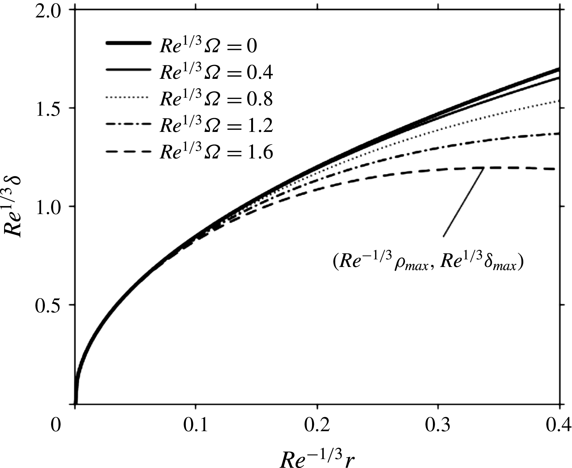
Figure 3 illustrates the influence of rotation on the boundary-layer height. In the limit of
 $\unicode[STIX]{x1D6FA}=0$
, the classical boundary-layer result is recovered (Watson Reference Watson1964; Schlichtling Reference Schlichtling2000). As expected, the rotation can have a tangible effect as it tends to lower the boundary-layer height. This is clearly reflected in (2.1b
) when expression (2.8) is used. We see that the centrifugal effect, which enhances inertial effect by growing like
 $Re\unicode[STIX]{x1D6FA}^{2}r$
, tends to compete with the radial convective effect, which is reflected by the term
 $Reuu_{r}$
. An estimate of the order of magnitude of this term is reached upon taking
 $u$
to correspond to the free-surface value. In this case, we see that
 $Reuu_{r}$
decays like
 $Re/r$
. Thus, close to the impingement point, the convective and viscous effects must balance in (2.1b
), and the boundary-layer height grows like
 $\unicode[STIX]{x1D6FF}\approx \sqrt{r/Re}$
regardless of the rotation speed. This is clearly depicted in figure 2 where all curves merge for
 $Re^{-1/3}r<0.1$
. Far from the impingement point, the centrifugal and viscous effects must balance, and the height decays like
 $\unicode[STIX]{x1D6FF}\approx \sqrt{1/Re\unicode[STIX]{x1D6FA}^{2}r}$
. Therefore, rotation has a similar effect of thinning the boundary layer like slip (Prince et al.
Reference Prince, Maynes and Crockett2012; Khayat Reference Khayat2016) or shear thinning (Khayat 2014). Interestingly, unlike slip flow, where the boundary-layer height invariably increases in the radial direction, a high rotation rate causes the boundary-layer height to decrease with radial distance after reaching a maximum as shown in figure 3.
A maximum in the boundary-layer height is therefore expected to emerge as a result of the growing centrifugal effect with radial distance. The maximum height
 $\unicode[STIX]{x1D6FF}_{max}$
coincides with the balance between the radial convective and the centrifugal effects, at a distance that is roughly dictated by
 $1/r\sim \unicode[STIX]{x1D6FA}^{2}r$
. Thus, the location
 $\unicode[STIX]{x1D70C}_{max}$
of the maximum decreases rather rapidly with rotation speed, like
 $1/\unicode[STIX]{x1D6FA}$
, and the maximum height behaves like
 $\unicode[STIX]{x1D6FA}^{-1/2}$
. Considering that the inherent reason of the boundary-layer growth is due to accumulating viscous effect, the location of the maximum boundary-layer height occurs closer to the disk centre when
 $\unicode[STIX]{x1D6FA}$
increases.
Influence of rotation in the developing boundary-layer region (ii). The boundary-layer thickness is plotted against the radial distance for different rotation speed.

We next examine the flow downstream of the transition point.
3.2 Influence of rotation on the transition location and film thickness
As the boundary layer grows with radial distance, it eventually invades the entire film width, merging with the jet free surface at
 $r=r_{0}$
. For
 $r<r_{\text{0}}$
and above the boundary-layer outer edge, at some height
 $z=h(r)>\unicode[STIX]{x1D6FF}(r)$
, lies the free surface. The height of the free surface in region (ii) is then determined from mass conservation inside and outside the boundary layer. Therefore, for
 $r<r_{0}$
,
 $$\begin{eqnarray}\int _{0}^{\unicode[STIX]{x1D6FF}(r)}u(r,z)\,\text{d}z+h(r)-\unicode[STIX]{x1D6FF}(r)={\displaystyle \frac{1}{2r}}.\end{eqnarray}$$
Upon substituting the velocity profile (3.1), the film thickness is obtained as
 $$\begin{eqnarray}h(r<r_{0})={\displaystyle \frac{1}{48}}{\displaystyle \frac{24+18r\unicode[STIX]{x1D6FF}-Re\unicode[STIX]{x1D6FA}^{2}r^{2}\unicode[STIX]{x1D6FF}^{3}}{r}}.\end{eqnarray}$$
The term
 $Re\unicode[STIX]{x1D6FA}^{2}r^{2}\unicode[STIX]{x1D6FF}^{3}$
reflects the thinning effect of rotation on the film thickness. In the absence of rotation, we recall that
 $\unicode[STIX]{x1D6FF}=2\sqrt{(70/39)(r/Re)}$
, so that
 $$\begin{eqnarray}h(r<r_{0};\unicode[STIX]{x1D6FA}=0)={\displaystyle \frac{1}{4}}\left({\displaystyle \frac{2}{r}}+\sqrt{{\displaystyle \frac{210}{13}}{\displaystyle \frac{r}{Re}}}\right).\end{eqnarray}$$
Hence, in the absence of rotation,
 $h$
decreases rapidly, like
 $1/r$
, near the disk centre, reaching a minimum, and increases like
 $\sqrt{r}$
further downstream. In contrast, in the presence of strong centrifugal effect, upon recalling that
 $\unicode[STIX]{x1D6FF}\sim \sqrt{1/Re\unicode[STIX]{x1D6FA}^{2}r}$
, we find that the film thickness also behaves like
 $h(r<r_{0})\sim \sqrt{1/Re\unicode[STIX]{x1D6FA}^{2}r}$
. This will be discussed further later.
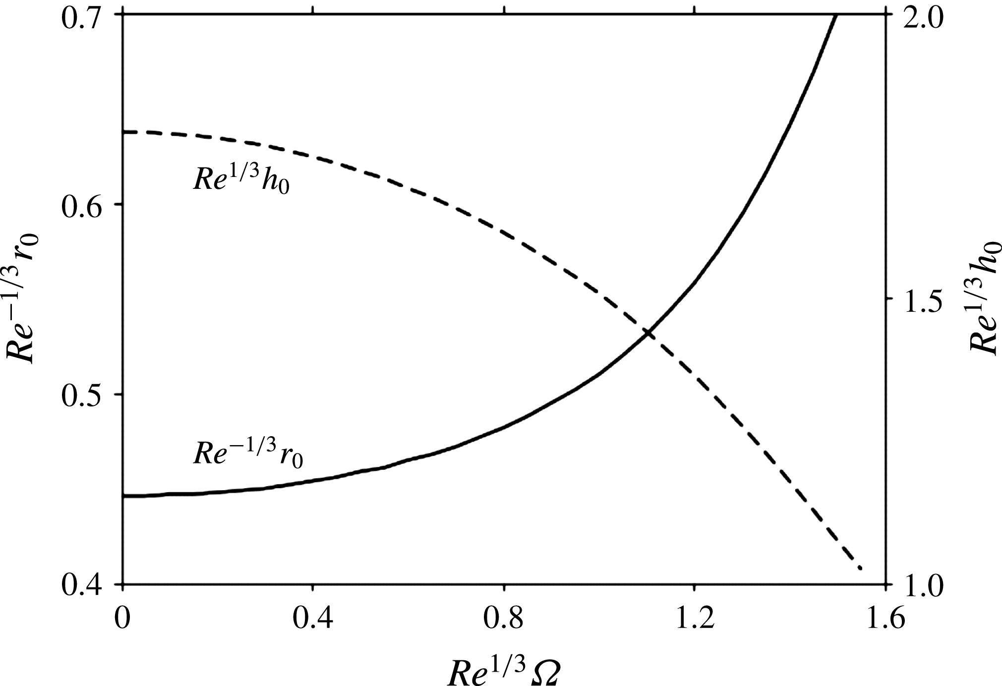
Figure 4 depicts the influence of rotation on the transition location
 $r_{0}$
and corresponding film thickness
 $h_{0}\equiv h(r_{0})$
, which are determined by setting
 $h(r_{0})=\unicode[STIX]{x1D6FF}(r_{0})$
. The transition location increases as the film becomes thinner with increasing rotation speed as inertia is enhanced by rotation. This is the same trend predicted for the effect of slip (see figure 8 of Khayat (Reference Khayat2016)). However, in contrast to the effect of slip, the rotation speed does not yield an asymptotic behaviour of the thickness for large
 $\unicode[STIX]{x1D6FA}$
. Another interesting contrasting behaviour is the slow deviation from the
 $\unicode[STIX]{x1D6FA}=0$
level for small
 $\unicode[STIX]{x1D6FA}$
in figure 4 as opposed to the strong departure for small slip.
Dependence of location and film thickness at the transition point between the developing and viscous boundary-layer regions (ii) and (iii).

In the absence of rotation, upon equating
 $h(r_{0};\unicode[STIX]{x1D6FA}=0)=1/4(2/r_{0}+\!\sqrt{(210/13)(r_{0}/Re)})$
and
 $\unicode[STIX]{x1D6FF}(r_{0};\unicode[STIX]{x1D6FA}=0)=2\sqrt{(70/39)(r_{0}/Re)}$
, we obtain
 $$\begin{eqnarray}r_{0}(\unicode[STIX]{x1D6FA}=0)=\left({\displaystyle \frac{78}{875}}Re\right)^{1/3}.\end{eqnarray}$$
In particular,
 $Re^{-1/3}r_{0}=0.447$
and
 $Re^{1/3}h(r_{0})=1.791$
are the limit values reflected in figure 4. In comparison, Watson’s transition location is given by
 $Re^{-1/3}r_{0}=9\sqrt{3}c(\unicode[STIX]{x03C0}-c\sqrt{3})/16\unicode[STIX]{x03C0}^{2}=0.463$
, where
 $c=1.402$
(Watson Reference Watson1964), which reflects a discrepancy less than 3 %.
4 Influence of rotation on the flow in the fully viscous layer
In region (iii), the potential flow in the radial direction ceases to exist, with the velocity
 $U(r)=u(r,z=h)$
at the free surface becoming dependent on
 $r$
. We assume a cubic velocity profile for
 $u(r,z)/U(r)$
, subject to conditions (2.2a
), (2.4a
) and (2.7a
). In this case,
 $U(r)$
is determined by using the mass conservation equation (2.9), yielding the following relation:
 $$\begin{eqnarray}U(r>r_{0})={\displaystyle \frac{24}{hr(Re\unicode[STIX]{x1D6FA}^{2}rh^{2}+30)}}.\end{eqnarray}$$
For
 $\unicode[STIX]{x1D6FA}=0$
, this equation agrees with equation (15) of Prince et al. (Reference Prince, Maynes and Crockett2012) upon setting their slip parameter equal to zero. The radial velocity profile is given as function of the surface velocity
 $U(r)$
:
 $$\begin{eqnarray}u(r>r_{0},z)={\displaystyle \frac{U}{4h^{3}}}\left[h^{2}(Re\unicode[STIX]{x1D6FA}^{2}h^{2}r+6)z-2Re\unicode[STIX]{x1D6FA}^{2}h^{3}rz^{2}+(Re\unicode[STIX]{x1D6FA}^{2}h^{2}r-2)z^{3}\right].\end{eqnarray}$$
This equation is equivalent to equation (3) of Bohr et al. (Reference Bohr, Putkaradze and Watanabe1997) for a stationary disk. In that case, the
 $r$
-dependent coefficients were also obtained using the same boundary conditions at the disk and the film surface.
Similar to (3.2), the integral form of the momentum equation reads:
 $$\begin{eqnarray}\left({\displaystyle \frac{\text{d}}{\text{d}r}}+{\displaystyle \frac{1}{r}}\right)\int _{0}^{h}(u^{2}-u)\,\text{d}z-\unicode[STIX]{x1D6FA}^{2}hr=-{\displaystyle \frac{1}{Re}}u_{z}(r,z=0).\end{eqnarray}$$
Substituting (4.2) into (4.3), we obtain the equation for the film thickness in the fully viscous region, which is integrated numerically for
 $r\geqslant r_{0}$
subject to
 $h(r=r_{0})=\unicode[STIX]{x1D6FF}(r_{0})$
. The resulting differential equation for
 $h$
is algebraically complicated and will not be displayed here. It takes a particularly simple form in the absence of rotation. Thus, for
 $\unicode[STIX]{x1D6FA}=0$
and
 $r\geqslant r_{0}$
, the problem reduces to the following equation and boundary condition:
 $$\begin{eqnarray}{\displaystyle \frac{\text{d}h}{\text{d}r}}=-{\displaystyle \frac{h}{r}}+{\displaystyle \frac{525}{136}}{\displaystyle \frac{r}{Re}},\quad h(r_{0},\unicode[STIX]{x1D6FA}=0)=2\sqrt{{\displaystyle \frac{70}{39}}{\displaystyle \frac{r_{0}}{Re}}},\end{eqnarray}$$
which admits
 $$\begin{eqnarray}h(r>r_{0};\unicode[STIX]{x1D6FA}=0)={\displaystyle \frac{175}{136Rer}}(r^{3}-r_{0}^{3})+2{\displaystyle \frac{r_{0}}{r}}\sqrt{{\displaystyle \frac{70}{39}}{\displaystyle \frac{r_{0}}{Re}}}={\displaystyle \frac{175}{136}}{\displaystyle \frac{r^{2}}{Re}}+{\displaystyle \frac{1}{5}}\left(4-{\displaystyle \frac{39}{68}}\right){\displaystyle \frac{1}{r}},\end{eqnarray}$$
as solution, where we recall
 $r_{0}=(78/875Re)^{1/3}$
from (3.7). Clearly, (4.5) indicates that the thickness increases like
 $h\sim r^{2}$
at large distance. The limit of large rotation speed will be discussed shortly. Figure 5 depicts the influence of rotation on the film thickness in the transition region. Results are shown for
 $Re^{1/3}\unicode[STIX]{x1D6FA}$
, ranging from 0 to 1.6. In the limit
 $\unicode[STIX]{x1D6FA}=0$
, Watson’s film thickness profile is essentially recovered, which is the only profile that increases with
 $r$
after exhibiting a strong minimum, as per (4.5). For comparison, Watson’s expression is reproduced here in dimensionless form:
 $$\begin{eqnarray}h(r>r_{0})={\displaystyle \frac{2\unicode[STIX]{x03C0}}{3\sqrt{3}}}{\displaystyle \frac{r^{2}}{Re}}+{\displaystyle \frac{3c(3\sqrt{3}c-\unicode[STIX]{x03C0})}{8\unicode[STIX]{x03C0}}}{\displaystyle \frac{1}{r}}.\end{eqnarray}$$
Thus, we have
 $h\simeq 1.21(r^{2}/Re)+0.685(1/r)$
from (4.5) compared to Watson’s
 $h\simeq 1.28(r^{2}/Re)+0.69(1/r)$
from (4.6), showing a surprisingly close agreement.
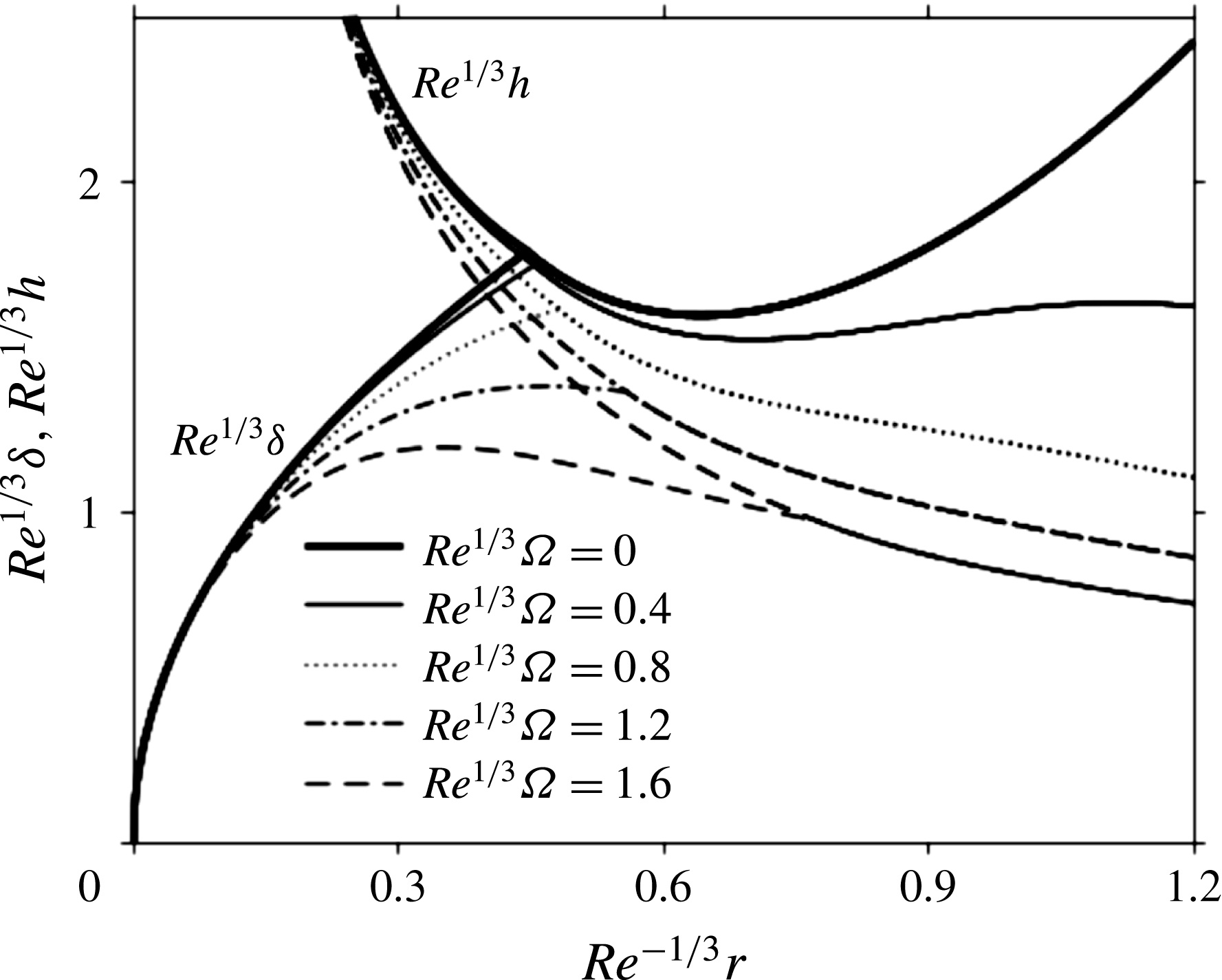
The minimum film thickness weakens considerably as the rotation speed is slightly increased. The transition occur s upstream of the minimum, with unmatched slopes between
 $h$
and
 $\unicode[STIX]{x1D6FF}$
at
 $r=r_{0}$
. For a faster spinning disk, the film acquires additional radial momentum, with reduced viscous effect (friction). The film thickness as well as the boundary-layer height decrease overall, and the minimum weakens further. As rotation intensifies further, the film does no longer exhibit a minimum in thickness. In the case of an infinite rotation speed, figure 5 indicates that the film thickness saturates to a finite value, which is practical since the film thickness cannot vanish. Also shown in this figure is the location of the minimum height pushed outward as effects of viscosity decrease, which is a combined effect of Reynolds number and rotation speed.
Influence of rotation on the developing boundary-layer height and film thickness. The transition location coincides with the intersection of the two heights.

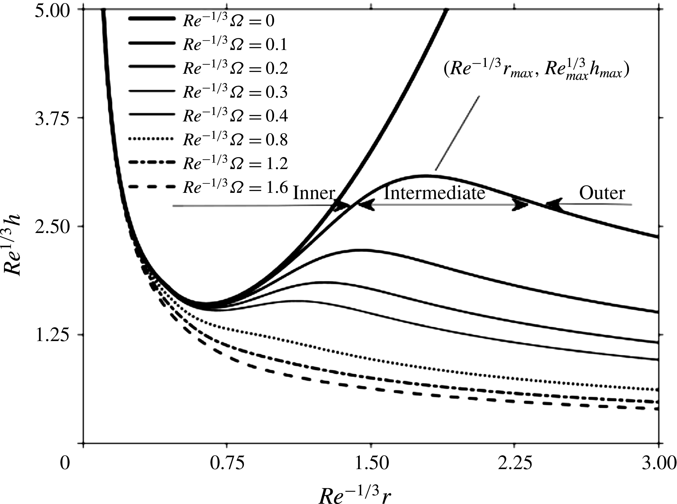
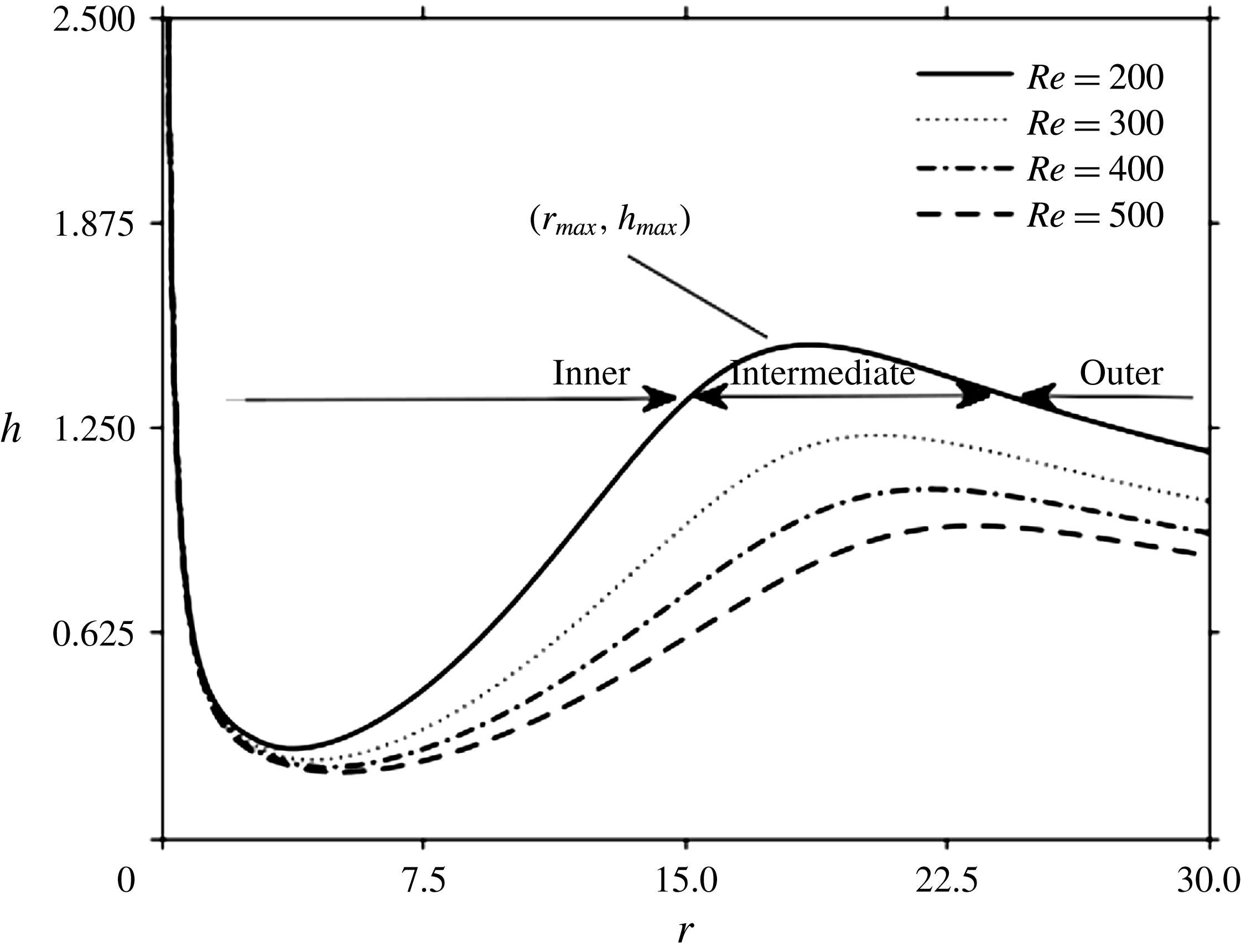
Figure 6 gives an overall view of the film thickness distribution. In addition to the minimum film thickness, there is also a maximum height whose location and strength depend on the interplay between convective and centrifugal effects. This was also observed by Ozar et al. (Reference Ozar, Cetegen and Faghri2003) in their experimental study on the flow over a rotating disk. Downstream of the transition location, the liquid film behaviour can be divided into three zones: the inner inertia-dominated region, the outer rotation-dominated region and the intermediate region in between. In the inertia-dominated region, the inertia and friction forces are dominant. The liquid film tends to slow down as a result of friction, and the film thickness increases as reported by Thomas et al. (Reference Thomas, Hankey, Faghri and Swanson1990). In the rotation-dominated region, centrifugal forces come into play, causing a thinning of the liquid film. Meanwhile in the transition region, both the viscous effect and centrifugal effect come into play and are in balance. Thus, the film thickness reaches a maximum in the transition region, where deceleration of the flow due to friction is compensated and eventually balanced by the acceleration due to centrifugal effect.
Influence of rotation on the thickness distribution upstream and downstream of the transition point
 $r=r_{0}$
. The inner, intermediate and outer subregions are shown for
 $Re^{1/3}\unicode[STIX]{x1D6FA}=0.1$
.

As is apparent from figure 6, at a given Reynolds number, the location where the maximum film thickness occurs, moves towards the centre of the disk as the rotation speed increases, which indicates that the centrifugal effect gradually dominates inertia. This is illustrated through the curves corresponding to
 $Re^{1/3}\unicode[STIX]{x1D6FA}=0.1,0.2,0.3$
. Eventually, upon further increase of the rotation speed, the centrifugal effect becomes dominant over the entire disk, except in region where convective effects appear to be always present. The film thickness decreases monotonically as the rotation speed increases, and becomes essentially independent of the radial distance far downstream. Also, the thickness becomes gradually insensitive to the rotation speed as indicated by the curve saturation in figure 5. This behaviour agrees closely with the measurements and leading-order asymptotic solution of Burns et al. (Reference Burns, Ramshaw and Jachuck2003). The development from inertial to centrifugal dominance will be further examined below once the surface velocity is discussed.
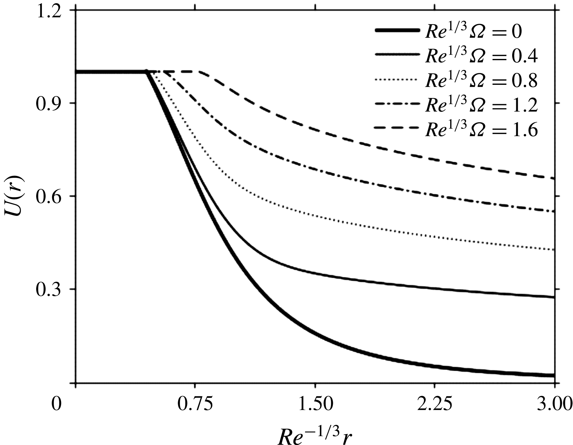
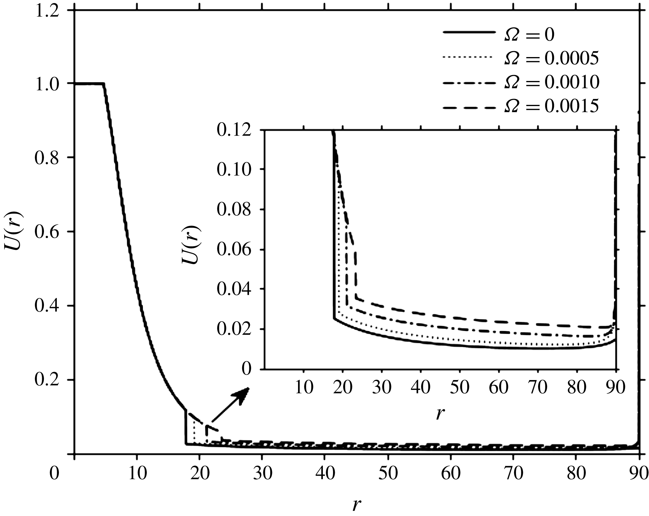
The influence of rotation on the corresponding free-surface velocity profiles is depicted in figure 7. Here the velocity in the developing boundary-layer region (ii) outside the boundary layer is equal to the uniform jet velocity, which then decreases monotonically with distance downstream of the transition location. We can see the significant effect of rotation on the surface velocity as it tends to enhance the radial flow but diminishes the rate at which the surface velocity decreases with radial distance, which is similar to the effect of slip (Prince et al. Reference Prince, Maynes and Crockett2012; Khayat Reference Khayat2016). However, the effect of rotation seems stronger than that of slip since slip is nothing but the drop in surface resistance, whereas rotation has an obvious effect of accelerating the flow. That is, the momentum dissipated by viscous stress is gradually recovered by the centrifugal force. The figure also suggests that when the rotation speed tends to infinity, the developing boundary-layer region dominates the entire flow, and the free-surface velocity saturates to a horizontal line which is the free jet velocity.
Influence of rotation on the velocity at the film surface upstream and downstream of the transition point
 $r=r_{0}$
. The transition point coincides with the location at which the velocity first deviates from 1.

In the absence of rotation, the surface velocity decreases rapidly. This behaviour is easily deduced from (4.1) upon setting
 $\unicode[STIX]{x1D6FA}=0$
and substituting (4.5) to obtain
 $$\begin{eqnarray}\displaystyle U(r>r_{0};\unicode[STIX]{x1D6FA}=0)={\displaystyle \frac{4}{5}}\left({\displaystyle \frac{175}{136Re}}(r^{3}-r_{0}^{3})+2r_{0}\sqrt{{\displaystyle \frac{70}{39}}{\displaystyle \frac{r_{0}}{Re}}}\right)^{-1}. & & \displaystyle\end{eqnarray}$$
In this case,
 $U$
decreases like
 $r^{-3}$
at large distance.
Although the explicit dependence of the film thickness and surface velocity on rotation speed and radial distance is complex, further insight is gained by examining the limits of negligible and dominant centrifugal effect. Figures 6 and 7 suggest the existence of three distinct subregions downstream of the transition point in the fully viscous layer region: an inner subregion close to the transition point where the convective effect dominates the centrifugal effect, an intermediate subregion where these two effects are comparable, and a subregion far from the transition point where the centrifugal effect is dominant. We observe that in all three subregions, the viscous effects are significant. An approximate relation between
 $U$
and
 $h$
may be deduced from the mass conservation equation (2.9):
 $$\begin{eqnarray}Uh\simeq {\displaystyle \frac{1}{2r}}.\end{eqnarray}$$
Consider first the inner subregion where inertia and viscous effects are dominant. In this case, (2.1b ) suggests that
 $$\begin{eqnarray}Re{\displaystyle \frac{U^{2}}{r}}\sim {\displaystyle \frac{U}{h^{2}}}.\end{eqnarray}$$
Using (4.8), we obtain
 $$\begin{eqnarray}U\sim {\displaystyle \frac{Re}{r^{3}}},\quad h\sim {\displaystyle \frac{r^{2}}{Re}}.\end{eqnarray}$$
This behaviour corresponds to the more explicit expression (4.5) for
 $h$
derived earlier in the absence of rotation and based on the cubic profile for velocity. The behaviour in (4.10) clearly corroborates the trends reported in figures 6 and 7 for the region close to the transition point
 $r=r_{0}$
.
Next, consider the situation in the intermediate subregion where both the convective and centrifugal effects, along with the viscous effects are significant. In this case, we have
 $$\begin{eqnarray}Re{\displaystyle \frac{U^{2}}{r}}\sim Re\unicode[STIX]{x1D6FA}^{2}r\sim {\displaystyle \frac{U}{h^{2}}}.\end{eqnarray}$$
These relations, along with (4.8), yield the following estimates for the maximum thickness, and corresponding location and velocity:
 $$\begin{eqnarray}h_{max}\sim {\displaystyle \frac{1}{\sqrt{Re\unicode[STIX]{x1D6FA}}}},\quad r_{max}\sim \left({\displaystyle \frac{Re}{\unicode[STIX]{x1D6FA}}}\right)^{1/4},\quad U_{max}\sim (Re\unicode[STIX]{x1D6FA}^{3})^{1/4}.\end{eqnarray}$$
Clearly, these estimates agree with the trends observed in figures 6 and 7 in the intermediate region. Thus, (4.12a–c
) indicates that, with increasing rotation speed, the radial location of the maximum thickness decreases towards the centre like
 $\unicode[STIX]{x1D6FA}^{-1/4}$
and the maximum thickness weakens and saturates like
 $\unicode[STIX]{x1D6FA}^{-1/2}$
, eventually disappearing altogether as shown in figure 6. This behaviour will be confirmed further below.
In the outer subregion, at large radial distance, the centrifugal effect becomes particularly dominant whereas inertia becomes insignificant. In this case, and in the absence of gravity, the centrifugal term must balance the viscous term in the radial momentum equation (2.1b
), suggesting that
 $Re\unicode[STIX]{x1D6FA}^{2}r\sim U/h^{2}$
. Consequently, upon using (4.8), the behaviours of the film thickness and surface velocity for large centrifugal effect become:
 $$\begin{eqnarray}h\sim (Re\unicode[STIX]{x1D6FA}^{2}r^{2})^{-1/3},\quad U\sim \left({\displaystyle \frac{Re\unicode[STIX]{x1D6FA}^{2}}{r}}\right)^{1/3}.\end{eqnarray}$$
These limit expressions closely corroborate the profiles reported in figures 6 and 7. In particular, the
 $h\sim \unicode[STIX]{x1D6FA}^{-2/3}$
behaviour reflects the saturation at large rotation speed in figure 6. Also, equation (4.13) reflects the faster decay with distance of the thickness compared to that of the velocity. Finally, we note that (4.13a
) is equivalent to the asymptotic behaviour obtained by Rauscher et al. (Reference Rauscher, Kelly and Cole1973).
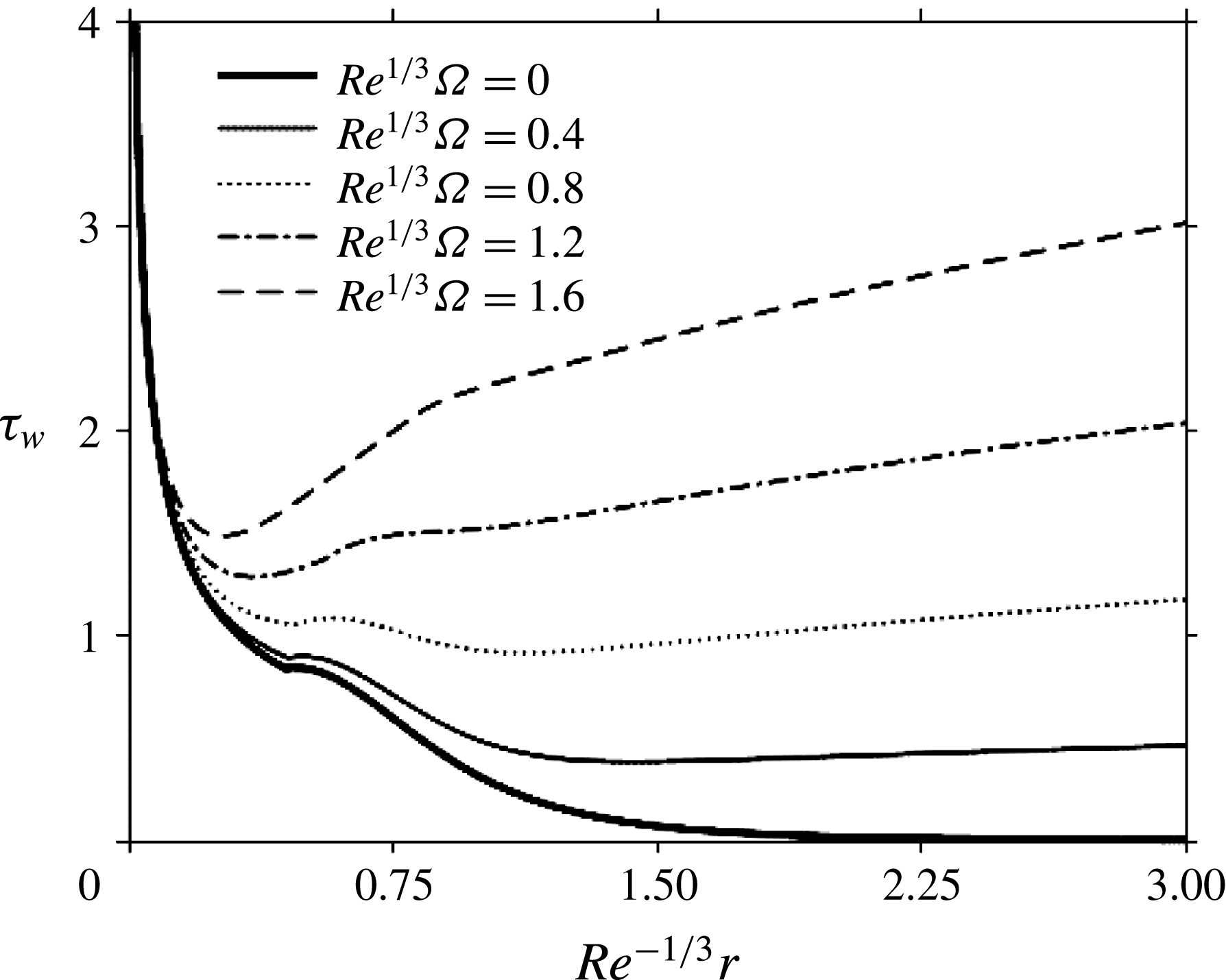
Figure 8 illustrates the development of the dimensionless wall shear stress at the disk (skin friction) for the same rotation speeds as in figures 6 and 7. From (4.1) and (4.2), we have
 $$\begin{eqnarray}\unicode[STIX]{x1D70F}_{w}(r>r_{0})=6{\displaystyle \frac{Re\unicode[STIX]{x1D6FA}^{2}h^{2}r+6}{h^{2}r(Re\unicode[STIX]{x1D6FA}^{2}h^{2}r+30)}}.\end{eqnarray}$$
The figure shows that the wall shear stress is always larger for a higher rotation speed anywhere along the disk. This larger shear stress, which reflects a larger shear rate at the disk, is the result of a thinner film thickness and a greater free-surface velocity caused by higher rotation speed as already reported in figures 6 and 7. The shear stress decreases rapidly in the developing boundary-layer region. For a stationary disk:
 $$\begin{eqnarray}\unicode[STIX]{x1D70F}_{w}(r>r_{0};\unicode[STIX]{x1D6FA}=0)={\displaystyle \frac{6}{5}}r\left[{\displaystyle \frac{175}{136Re}}(r^{3}-r_{0}^{3})+2r_{0}\sqrt{{\displaystyle \frac{70}{39}}{\displaystyle \frac{r_{0}}{Re}}}\right]^{-2}.\end{eqnarray}$$
In this case, after the rapid drop,
 $\unicode[STIX]{x1D70F}_{w}$
exhibits a maximum before decaying monotonically. At large radial distance, the shear stress decays like
 $r^{-5}$
for a stationary disk as a result of film thickening and absence of rotation (see
 $\unicode[STIX]{x1D6FA}=0$
curves in figures 6 and 7). In contrast, the shear stress on a rotating disk decreases to a minimum after which
 $\unicode[STIX]{x1D70F}_{W}$
increases relatively slowly with
 $r$
. The minimum strengthens and moves towards the centre of the disk with increasing rotation speed, signalling the increasing dominance of centrifugal effect over the entire viscous boundary-layer region.
Figure 8 suggests that
 $\unicode[STIX]{x1D70F}_{W}$
increases essentially linearly with radial distance for moderate rotation speed. In the outer region, upon substituting (4.13a
) into (4.15), we have
 $$\begin{eqnarray}\unicode[STIX]{x1D70F}_{w}\sim (Re^{2}\unicode[STIX]{x1D6FA}^{4}r)^{1/3}.\end{eqnarray}$$
We also arrive at the same result if we write
 $\unicode[STIX]{x1D70F}_{w}\sim U/h$
and use (4.10). This shows that the shear stress deviates from the linear growth with radial distance, and behaves closer to
 $r^{1/3}$
, which is also noticeable from figure 8 for
 $Re\unicode[STIX]{x1D6FA}^{2}=1.6$
. Also, the behaviour
 $\unicode[STIX]{x1D70F}_{w}\sim \unicode[STIX]{x1D6FA}^{4/3}$
reflects the mildly nonlinear (slightly faster than linear) growth of the shear stress with rotation speed depicted in figure 8.
Influence of rotation speed on the wall shear stress upstream and downstream of the transition point
 $r=r_{0}$
.

We next consider the effect of inertia by varying the Reynolds number and fixing the rotation speed to
 $\unicode[STIX]{x1D6FA}=0.02$
. Figure 9 shows the film thickness for
 $Re$
between 200 and 500. An increase in the Reynolds number causes an increase in film inertia. Therefore, a higher centrifugal force is required to overcome the higher inertial force to maintain the flow. If the rotation speed is kept constant and the Reynolds number is increased, then the maximum film thickness location travels towards the edge of the disk while the maximum weakens. This is in agreement with (4.12a–c
). Since the radial location influences the magnitude of centrifugal effects, the region where the centrifugal and inertia forces are comparable, moves towards the edge of the disk.
Influence of inertia on the film thickness upstream and downstream of the transition point. Here
 $\unicode[STIX]{x1D6FA}=0.02$
. The inner, intermediate and outer subregions are indicated for the
 $Re=200$
curve.

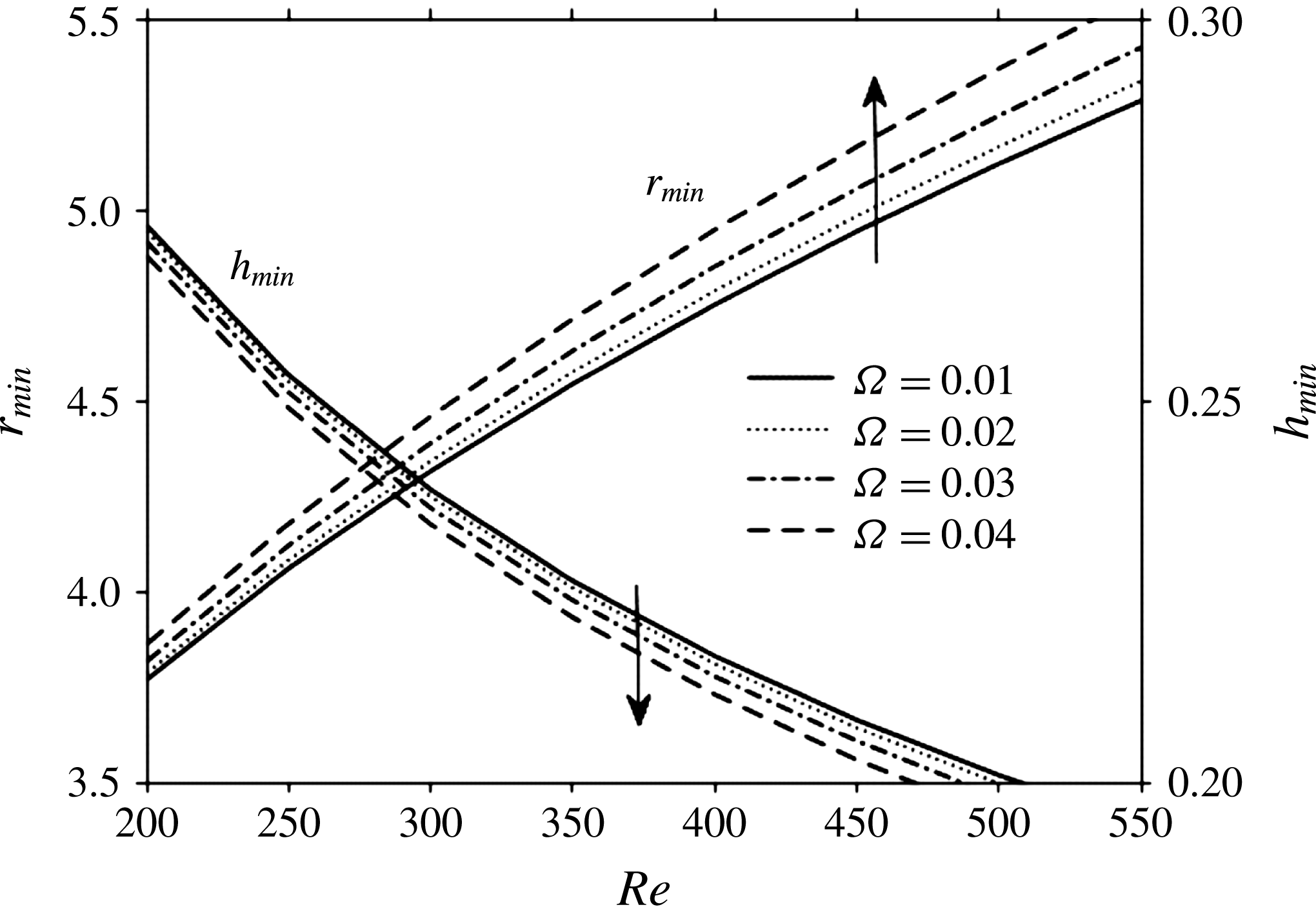
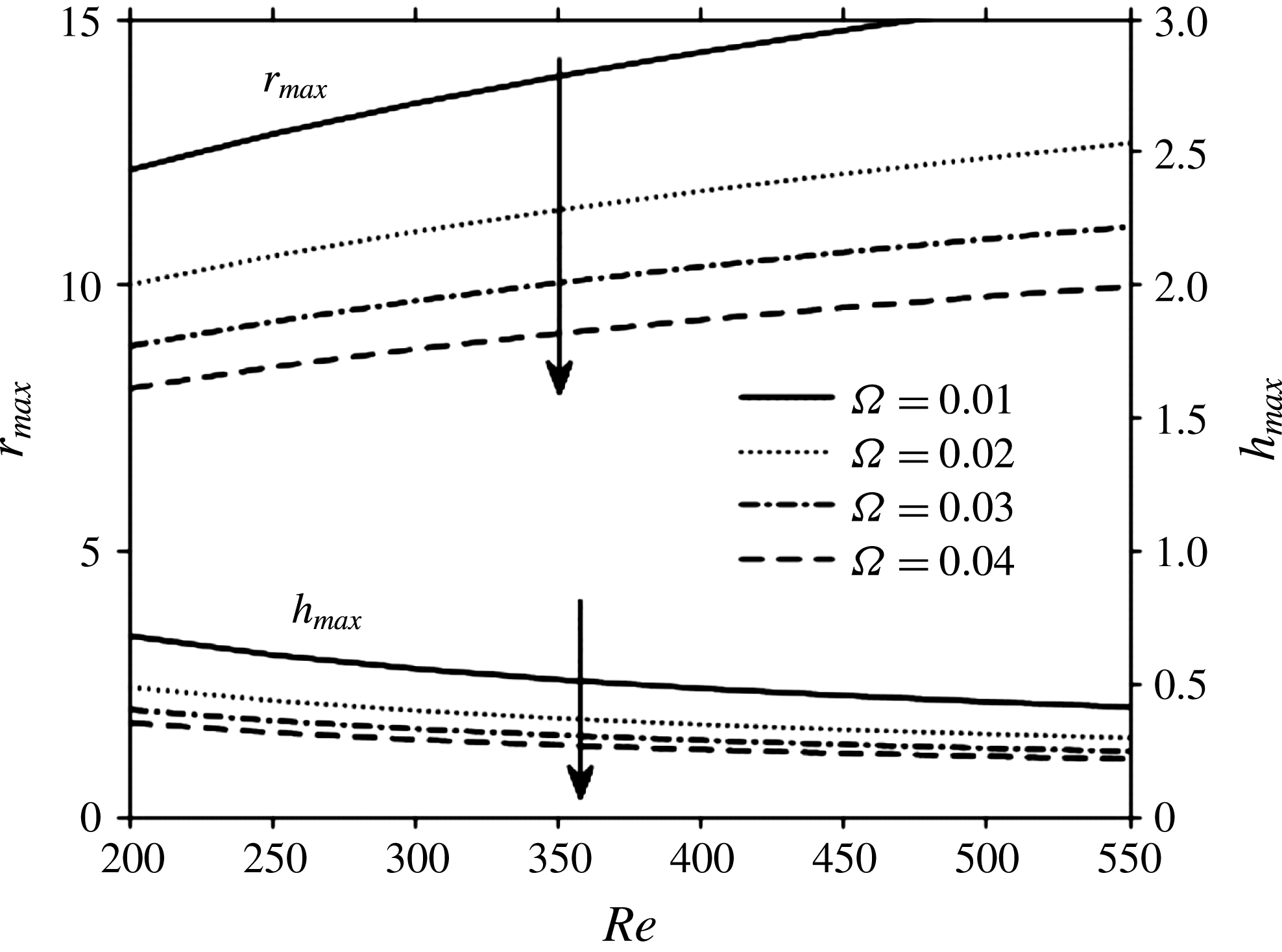
A more explicit illustration is given in figures 10 and 11, where both the location and the values of the minimum thickness as well as the maximum thickness are reported. Figure 10 indicates that the location of the minimum thickness moves outwards with rotation as well as inertia, whereas the minimum height decreases as argued earlier. In figure 11, however, the location and the magnitude of the maximum height behave differently as emphasized by the arrows.
Influence of inertia and centrifugal effects on the minimum film thickness and its location. Arrows indicate direction of increasing rotation speed.

The trends in figure 10 are well reflected by the earlier analysis and (4.12a–c
). In particular,
 $r_{max}\sim (Re/\unicode[STIX]{x1D6FA})^{1/4}$
suggests that the location of the maximum increases with inertia like
 $Re^{1/4}$
and decreases with rotation speed like
 $\unicode[STIX]{x1D6FA}^{-1/4}$
, reflecting the saturation in figure 11 with respect to
 $Re$
and
 $\unicode[STIX]{x1D6FA}$
, respectively. Similarly, the behaviour
 $h_{max}\sim 1/\sqrt{Re\unicode[STIX]{x1D6FA}}$
is well represented in figure 11.
Influence of inertia and centrifugal effects on the maximum film thickness and its location. Arrows indicate direction of increasing rotation speed.

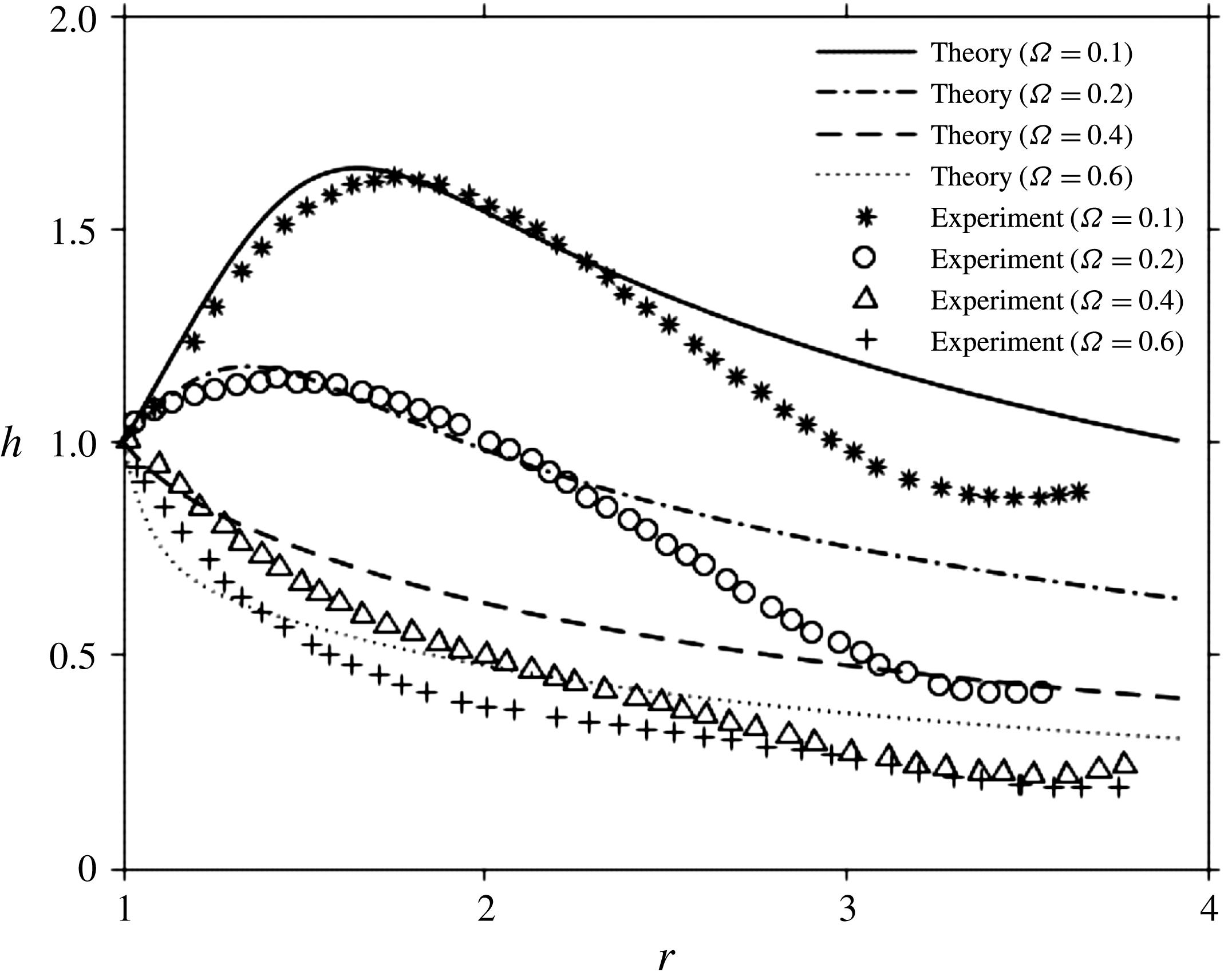
Although there are no film thickness measurements for the flow impinging on a rotating disk, some data exist for a thin film emanating radially on a rotating disk. In particular Ozar et al. (Reference Ozar, Cetegen and Faghri2003) examined the flow of water emerging from a collar. In an effort to validate the observed behaviour in the viscous region (iii), we carry out a direct comparison with their measurements by solving (4.3) for the thickness distribution. We choose the initial thickness and location to correspond to the height and radius of the collar, respectively. Figure 12 depicts the influence of rotation on the thickness distribution. The figure shows that the flow features predicted by our formulation in region (iii) are realistic as they are also observed experimentally. In particular, figure 12 shows a good agreement between theory and experiment regarding the emergence of the thickness maximum and its location. As theory suggests (see also figure 11), the observed maximum height and location decrease with increasing rotation speed.
Influence of rotation speed on the maximum film thickness and its location. Comparison between theory and the measurements of Ozar et al. (Reference Ozar, Cetegen and Faghri2003). The data correspond to
 $Q=3~\text{l}~\text{mn}^{-1}$
.

5 Influence of rotation on the hydraulic jump
In this section, we consider the axisymmetric flow in region (iv), the hydraulic jump region. The flow on a stationary disk will be revisited, with discussion focused on the prediction or determination of the thickness at the edge of the disk, which will be used as a boundary condition. The resulting arguments will be extended for the flow over a rotating disk. Although the flow downstream of the jump may be assumed to be inviscid or viscous, only the viscous flow will be examined as it seems to reflect closer the real flow. In fact, the hydraulic jump is associated with a considerable energy loss which is traditionally difficult to determine. As such, the energy equation is not suitable for the analysis of the hydraulic jump (Crowe Reference Crowe2009). Consequently, a momentum balance approach is applied across the jump. In addition, the surface-tension effect will be included although a large jump radius is anticipated in the presence of rotation.
5.1 General formulation
Using equation (2.1a ), the integral form of (2.1b ) at any location becomes
 $$\begin{eqnarray}{\displaystyle \frac{1}{r}}{\displaystyle \frac{\text{d}}{\text{d}r}}r\int _{0}^{h}(u^{2}-u)\,\text{d}z-{\displaystyle \frac{1}{r}}\int _{0}^{h}v^{2}\,\text{d}z=-{\displaystyle \frac{1}{Fr^{2}}}\int _{0}^{h}{\displaystyle \frac{\unicode[STIX]{x2202}p}{\unicode[STIX]{x2202}r}}\,\text{d}z-{\displaystyle \frac{1}{Re}}\left.{\displaystyle \frac{\unicode[STIX]{x2202}u}{\unicode[STIX]{x2202}z}}\right|_{z=0}.\end{eqnarray}$$
We recall the position of the hydraulic jump as being
 $r=r_{j}$
, and let
 $h_{j}=h(r=r_{j})$
and
 $u_{j}(z)=u(r=r_{j},z)$
be the film thickness and radial velocity component immediately upstream of the jump (see figure 1). Downstream of the jump
 $(r>r_{j})$
, the film height and velocity are denoted by
 $H(r)$
and
 $U(r,z)$
respectively. Immediately downstream of the jump, we introduce
 $H_{j}=H(r=r_{j})$
and
 $U_{j}(z)=U(r=r_{j},z)$
. We observe that the azimuthal velocity component at the jump is given by
 $v_{j}=\unicode[STIX]{x1D6FA}r_{j}$
as per (2.8). Across the jump, equation (5.1) is applied to a control volume of width
 $\unicode[STIX]{x0394}r$
in the radial direction, yielding
 $$\begin{eqnarray}\displaystyle & & \displaystyle \int _{0}^{H_{j}}(U_{j}^{2}-U_{j})\,\text{d}z-\int _{0}^{h_{j}}(u_{j}^{2}-u_{j})\,\text{d}z-{\displaystyle \frac{\unicode[STIX]{x0394}r}{r_{j}}}\int _{0}^{h_{j}}v_{j}^{2}\,\text{d}z\nonumber\\ \displaystyle & & \displaystyle \qquad =-{\displaystyle \frac{1}{Fr^{2}}}\left(\int _{0}^{H_{j}}P_{j}\,\text{d}z-\int _{0}^{h_{j}}p_{j}\,\text{d}z\right)-{\displaystyle \frac{\unicode[STIX]{x0394}r}{Re}}\left.{\displaystyle \frac{\unicode[STIX]{x2202}u_{j}}{\unicode[STIX]{x2202}z}}\right|_{z=0}.\end{eqnarray}$$
Here,
 $p_{j}(z)$
and
 $P_{j}(z)$
are the pressures immediately upstream and downstream of the jump. Since the width of the jump
 $\unicode[STIX]{x0394}r$
is assumed to be small, the terms in (5.2) containing
 $\unicode[STIX]{x0394}r$
become negligible. In this case, we recall the pressure terms from (2.6), and use (2.9) for mass conservation. In addition, following Bush & Aristoff (Reference Bush and Aristoff2003), we include the effect of surface tension. The resulting equation takes the same form as in the case of a stationary disk, namely
 $$\begin{eqnarray}{\displaystyle \frac{1}{2}}(H_{j}^{2}-h_{j}^{2})+{\displaystyle \frac{1}{Bo}}{\displaystyle \frac{(H_{j}-h_{j})}{r_{j}}}=Fr^{2}\int _{0}^{h_{j}}u_{j}^{2}\,\text{d}z-Fr^{2}\int _{0}^{H_{j}}U_{j}^{2}\,\text{d}z.\end{eqnarray}$$
We observe that the effect of rotation is reflected implicitly in (5.3) in the height and velocity upstream and downstream of the jump. As in the case of a stationary disk, some assumptions are made regarding the nature of the flow downstream of the jump.
In this work, we follow Duchesne et al. (Reference Duchesne, Lebon and Limat2014), and adopt a lubrication flow assumption in the presence of rotation. In this case, a differential equation for
 $H$
can be obtained by neglecting the first two inertia terms in (2.1b
). In other words, we assume
 $Re$
to be small but
 $Re\unicode[STIX]{x1D6FA}^{2}$
non-negligible. We note that the hydrostatic pressure term is not negligible due to the large film thickness downstream of the jump. Consequently, the remaining terms in (2.1b
), the hydrostatic pressure, the viscous and the centrifugal effects, must balance:
 $$\begin{eqnarray}Re\unicode[STIX]{x1D6FA}^{2}r=G{\displaystyle \frac{\text{d}H}{\text{d}r}}-U_{zz}.\end{eqnarray}$$
By applying the no-slip condition at the fluid–disk interface and the no-shear condition at the free surface, (5.4) can be integrated to yield the velocity downstream of the jump:
 $$\begin{eqnarray}U(r,z)=Re\left({\displaystyle \frac{1}{Fr^{2}}}{\displaystyle \frac{\text{d}H}{\text{d}r}}-\unicode[STIX]{x1D6FA}^{2}r\right)\left({\displaystyle \frac{z^{2}}{2}}-Hz\right).\end{eqnarray}$$
Upon inserting
 $U$
into the mass conservation equation (2.9) and integrating, the governing equation for the film thickness downstream of the jump becomes
 $$\begin{eqnarray}{\displaystyle \frac{\text{d}H}{\text{d}r}}=-{\displaystyle \frac{3}{2}}{\displaystyle \frac{Fr^{2}}{Re}}{\displaystyle \frac{H^{-3}}{r}}+Fr^{2}\unicode[STIX]{x1D6FA}^{2}r.\end{eqnarray}$$
The corresponding velocity reduces to
 $$\begin{eqnarray}U(r,z)=-{\displaystyle \frac{3}{2r}}H^{-3}\left({\displaystyle \frac{z^{2}}{2}}-Hz\right).\end{eqnarray}$$
The problem remains open as to the existence of an additional relation, which would allow us to determine uniquely the height and the location of the jump. This additional relation can be based on a boundary condition for the film height specified at the edge of the disk, that is
 $H(r=r_{\infty })=H_{\infty }$
. However, the specification of the height at the edge is theoretically not a simple matter. We discuss this issue by revisiting first the flow over a stationary disk.
5.2 The hydraulic jump over a stationary disk
In the absence of disk rotation, and subject to
 $H(r=r_{\infty })=H_{\infty }$
, an analytical solution exists for (5.6):
 $$\begin{eqnarray}H(r)=\left(H_{\infty }^{4}+6{\displaystyle \frac{Fr^{2}}{Re}}\ln \left({\displaystyle \frac{r_{\infty }}{r}}\right)\right)^{1/4}.\end{eqnarray}$$
Obviously, in the presence of radial flow, the film thickness at the edge of the disk cannot be zero. Direct measurements by Duchesne et al. (Reference Duchesne, Lebon and Limat2014) of this edge thickness, performed at nearly 5 mm of the disk perimeter in their experiment, give a nearly constant value of 3 mm with a weak power-law variation not exceeding a few per cent. This constant thickness value is very close to the capillary length
 $\sqrt{\unicode[STIX]{x1D6FE}/\unicode[STIX]{x1D70C}g}$
of the fluid, which results from the balance of forces between the hydrostatic pressure and the surface tension at the disk perimeter. This value is also consistent with the measurements of Dressaire et al. (Reference Dressaire, Courbin, Crest and Stone2010). Similarly, we assume here that the film thickness at the edge of the disk is essentially equal to the film thickness the liquid exhibits under static conditions. This is not an unreasonable assumption since the flow downstream of the jump has predominantly the character of gradually varied flow. This static thickness is governed by the minimum free energy, and was given by Lubarda & Talke (Reference Lubarda and Talke2011) as
 $h_{s}=2\sqrt{\unicode[STIX]{x1D6FE}/\unicode[STIX]{x1D70C}g}\sin (\unicode[STIX]{x1D703}_{Y}/2)$
, where
 $\unicode[STIX]{x1D703}_{Y}$
is the contact angle.
In addition, in order to explore the small variation of edge thickness with flow rate as observed by Duchesne et al. (Reference Duchesne, Lebon and Limat2014), we resort to a minimum mechanical energy principle (Yang & Chen Reference Yang and Chen1992; Yang, Chen & Hsu Reference Yang, Chen and Hsu1997). This principle states that a fluid flowing over the edge of a disk under the influence of a hydrostatic pressure gradient will adjust itself so that the mechanical energy within the fluid will be minimum with respect to the film thickness at the disk edge. We note that this approach originates from open-channel hydraulics (Bakhmeteff Reference Bakhmeteff1966). Consequently, the contribution on the thickness at the edge of the disk can be calculated by setting the derivative of the mechanical energy with respect to the film thickness equal to zero, that is
 $$\begin{eqnarray}{\displaystyle \frac{\unicode[STIX]{x2202}}{\unicode[STIX]{x2202}H}}\int _{0}^{H}\left(Fr^{2}{\displaystyle \frac{U^{2}}{2}}+H\right)\,\text{d}z=0.\end{eqnarray}$$
After substituting for
 $U$
from (5.7) into (5.9), we obtain the dependence of the film thickness on the Froude number (flow rate) at the edge of the disk:
 $(3/40)^{1/3}(Fr/r_{\infty })^{2/3}$
.
Taking into consideration this small dependence, we obtain the dimensionless film thickness at the edge as
 $$\begin{eqnarray}H_{\infty }=2\sqrt{{\displaystyle \frac{1}{Bo}}}\sin \left({\displaystyle \frac{\unicode[STIX]{x1D703}_{Y}}{2}}\right)+\left({\displaystyle \frac{3}{40}}\right)^{1/3}\left({\displaystyle \frac{Fr}{r_{\infty }}}\right)^{2/3}.\end{eqnarray}$$
Upon specifying the thickness
 $H(r=r_{\infty })=H_{\infty }$
at the edge of the disk as per (5.10), we obtain the film thickness distribution downstream of the jump from (5.8), which is then substituted into the momentum balance equation (5.3) to determine the location of the jump. The value of
 $\unicode[STIX]{x1D703}_{Y}$
may then be adjusted from experiment. For the current problem, we achieve a good agreement with the measurements of Dressaire et al. (Reference Dressaire, Courbin, Crest and Stone2010) by taking
 $\unicode[STIX]{x1D703}_{Y}=90^{\circ }$
. This value is within the range of values measured for water on polydimethylsiloxane (Diversified Enterprises 2009), which is the material used by Dressaire et al. (Reference Dressaire, Courbin, Crest and Stone2010) for their disk.
The dependence of the jump location on the Froude number is reported in figure 13, where a comparison with experiment is presented based on the data of Dressaire et al. (Reference Dressaire, Courbin, Crest and Stone2010) for water, leading to good agreement. The original experimental data were reported in terms of the flow rate for a jet radius of 1 mm and a speed ranging approximately from 3 to
 $16~\text{m}~\text{s}^{-1}$
. In this case, taking
 $g\simeq 10~\text{m}~\text{s}^{-2}$
,
 $\unicode[STIX]{x1D708}=10^{-6}~\text{m}^{2}~\text{s}^{-1}$
and
 $\unicode[STIX]{x1D6FE}=70~\text{dyn}~\text{cm}^{-1}$
, we have
 $Bo=0.13$
and
 $G=10^{-2}$
.
Dependence of hydraulic jump location on flow rate (Froude number) for a stationary disk. The figure shows the comparison between the current theoretical predictions and the measurements of Dressaire et al. (Reference Dressaire, Courbin, Crest and Stone2010) for a water jet.

Bohr et al. (Reference Bohr, Dimon and Putzkaradze1993) and Rojas, Argentina & Tirapegui (Reference Rojas, Argentina and Tirapegui2013) found that the jump radius scales approximately as
 $Q^{5/8}\unicode[STIX]{x1D708}^{-3/8}g^{-1/8}$
. Avedisian & Zhao (Reference Avedisian and Zhao2000) investigated the circular hydraulic jump experimentally for normal and reduced gravity conditions. They measured the jump diameter and shape at the free liquid surface for an impinging jet on a stationary disk. Based on the reported two values of the flow rate and two gravitational acceleration data provided, we find that the location of the jump behaves close to
 $g^{-1/9}$
, roughly confirming the scaling of Bohr et al. (Reference Bohr, Dimon and Putzkaradze1993) for low gravity. Using the current scaling, the dimensionless form of Bohr et al. estimate can be written in terms of the transition location and the Froude number as
 $r_{j}\sim r_{0}^{9/8}Fr^{1/4}$
, where we recall
 $r_{0}(\unicode[STIX]{x1D6FA}=0)=(78/875Re)^{1/3}$
from (3.7). More recently, Duchesne et al. (Reference Duchesne, Lebon and Limat2014) derived a more accurate estimate involving a logarithmic correction based on the thin-film approach. When cast in dimensionless form, we find that the jump location behaves like
 $r_{j}\sim Fr_{j}^{-1}Fr^{5/8}G^{-3/8}$
, where
 $Fr_{j}$
is the Froude number defined in terms of the jump height and the average velocity immediately after the jump. In our notation,
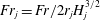 $Fr_{j}=Fr/2r_{j}H_{j}^{3/2}$
. Duchesne et al. (Reference Duchesne, Lebon and Limat2014) found that
 $Fr_{j}$
remains sensibly independent of the flow rate (constant with respect to
 $Fr$
), especially for a jet of fluid of low viscosity or at relatively large flow rate. Figure 14 shows the behaviour of
 $Fr_{j}$
against
 $Fr$
, corresponding to the prediction in figure 13, based on the current formulation. It is found that
 $Fr_{j}$
remains sensibly equal to 0.15. As a way to validate the current approach based on the cubic velocity profile, we also included in figure 14 the result based on Watson’s similarity solution, which indicates that both approaches yield essentially the same value for
 $Fr_{j}$
. As a reference, we also reproduced the measurements of Duchesne et al. (Reference Duchesne, Lebon and Limat2014) for silicon oil. In this case, it turns out that we essentially have
 $Fr_{j}\simeq 0.33$
. However, the data also suggest a deviation from the constant level at very flow rate. This issue is further explored next by comparing the location of the jump in the low flow rate range.
It appears that in order to determine both the location and the height of the jump, we seem to have two alternatives: fixing the value of
 $Fr_{j}$
or imposing the film thickness at the edge. Based on the results reported in figures 13 and 14, the two alternatives are essentially equivalent. It is therefore important to further examine conditions where
 $Fr_{j}$
may not remain independent of the flow rate. This is likely the case for impinging flow at low flow rate or a fluid of small viscosity. For this purpose, we conduct a comparison against the data of Hansen et al. (Reference Hansen, Horluck, Zauner, Dimon, Ellegaard and Creagh1997), who measured the position of the hydraulic jump against the flow rate, ranging from 0 to
 $60~\text{cm}^{3}~\text{s}^{-1}$
. In this case, the contact angle in (5.10) was taken for water and glass as
 $35^{\circ }$
(Vicente, Andre & Ferreira Reference Vicente, Andre and Ferreira2012). Figure 15 depicts the comparison between our formulation and experiment. The experimental data are reproduced in dimensionless form. The distribution of
 $Fr_{j}$
versus
 $Fr$
is also included for reference. The figure clearly confirms that
 $Fr_{j}$
remains constant over the large Froude number (flow rate) range. At small flow rate,
 $Fr_{j}$
increases rather rapidly as
 $Fr$
tends to zero.
Dependence of
 $Fr_{j}$
on the flow rate (Froude number) for a stationary disk. The solid and dashed lines show the results corresponding to the configuration of Dressaire et al. (Reference Dressaire, Courbin, Crest and Stone2010) for water, based on the current cubic and similarity profiles, respectively. The data corresponding to silicon oil from Duchesne et al. (Reference Duchesne, Lebon and Limat2014) are also included.

It is clear from figures 13 and 15 that the range of Froude numbers is not the same. The data of Hansen et al. (Reference Hansen, Horluck, Zauner, Dimon, Ellegaard and Creagh1997) are restricted to the very low range with no overlap with the data of Dressaire et al. (Reference Dressaire, Courbin, Crest and Stone2010). Therefore, we confirm from the observations of Duchesne et al. (Reference Duchesne, Lebon and Limat2014) as well as from their data in figure 14, that
 $Fr_{j}$
is not expected to remain constant in the low Froude number range.
Dependence of hydraulic jump location on flow rate (Froude number) for a stationary disk. The figure shows the comparison between the current theoretical predictions and the measurements of Hansen et al. (Reference Hansen, Horluck, Zauner, Dimon, Ellegaard and Creagh1997) for a water jet on a glass disk. The distribution of
 $Fr_{j}$
is also included.

Finally, we examine the validity of our approach regarding the actual size and shape of the jump. In their experiment of the flow of a thin film, Ozar et al. (Reference Ozar, Cetegen and Faghri2003) measured the jump profile against the radial distance on a stationary disk. The comparison between theory and experiment is reported in figure 16 for two different flow rates for a disk of radius 203 mm or
 $r_{\infty }=4$
. In this case, we take the contact angle for water and aluminium to be
 $70^{\circ }$
(Majeed Reference Majeed2014). For
 $Q=7~\text{l}~\text{mn}^{-1}$
, figure 16(a) shows that the jump is located far upstream of the disk edge
 $(r\approx 2)$
, whereas for
 $Q=15~\text{l}~\text{mn}^{-1}$
, figure 16(b) shows that the jump is located close to the edge. In both cases, the jump height exhibits a maximum and tapers rather rapidly near the edge. The comparison shows a close agreement for the thickness distribution upstream of the jump as well as for the (average) location and height of the jump for the two flow rates.
Comparison between theory and the measurements of Ozar et al. (Reference Ozar, Cetegen and Faghri2003) for the hydraulic jump of a thin film flowing on a stationary disk for
 $Q=7~\text{l}~\text{mn}^{-1}$
(a) and
 $Q=15~\text{l}~\text{mn}^{-1}$
(b).

5.3 The hydraulic jump over a rotating disk
In the case of a rotating disk, the thickness at the edge is expected to vary with the speed of rotation as well as the jet flow rate and surface tension. In this case, while the minimum energy principle is expected to hold, the static film thickness must be adjusted to account for rotation. We expect the thickness at the edge to decrease with rotation speed and increase with the flow rate as it should somehow reflect a balance between the centrifugal acceleration, the hydrostatic pressure and the surface tension. However, the measurements of Duchesne et al. (Reference Duchesne, Lebon and Limat2014) as well as those of Dressaire et al. (Reference Dressaire, Courbin, Crest and Stone2010) seem to suggest little influence of the flow rate, which is also supported by our predictions in § 5.2 above. Although these observations are conclusive for a stationary disk, we expect them to hold for a rotating disk.
However, the influence of rotation speed on the thickness at the edge of a rotating disk remains unaddressed. Here, we examine the effect of rotation by taking guidance from the extensive existing insight in thin-film spin coating. In this process, a drop of liquid solution is deposited onto a rotating substrate (wafer). After an initial acceleration, the liquid reaches a uniform thickness that is sufficiently small for the viscous shear drag to balance the centrifugal acceleration. At this stage, the film begins to dry up as the solvent evaporates, ultimately exhibiting a constant and steady thickness. Theory as well as experiment suggest that the final thickness varies with rotation speed like
 $h_{r}\sim \unicode[STIX]{x1D708}^{1/3}\unicode[STIX]{x1D714}^{-2/3}$
(Hall, Underhill & Torkelson Reference Hall, Underhill and Torkelson1998), where the kinematic viscosity
 $\unicode[STIX]{x1D708}$
appears to be the main influencing liquid property. This behaviour is observed at relatively large spin speed, and does not take into account the static limit that corresponds to
 $\unicode[STIX]{x1D714}=0$
. We find the overall behaviour that seems to fit well experiment to be of the form:
 $$\begin{eqnarray}h_{r}={\displaystyle \frac{h_{s}}{1+\unicode[STIX]{x1D6FC}h_{s}\left({\displaystyle \frac{\unicode[STIX]{x1D714}^{2}}{\unicode[STIX]{x1D708}}}\right)^{1/3}}}.\end{eqnarray}$$
Here
 $\unicode[STIX]{x1D6FC}$
is an empirical coefficient in units of
 $(\text{s}~\text{m})^{-1/3}$
. To illustrate the applicability of (5.11), we examine the flow of photoresist AZ6600 liquid series, which are liquid films used as resistant substance applied as a coating to protect a surface during some process, for example to prevent dye or glaze adhering (MicroChemicals 2013). Figure 17 shows the data and curves based on (5.11) for five AZ6600 liquid films based on measurements reported by Clariant GmbH (see reference source below). In this case, all five liquid films have sensibly the same surface tension for a contact angle of
 $90^{\circ }$
, namely
 $10~\text{dyn}~\text{cm}^{-2}$
(Bauer et al.
Reference Bauer, Drescher, Silz, Frankenfeld and Illig1997), yielding
 $h_{s}=1.7~\text{mm}$
. The kinematic viscosities are as follows: 19 cSt (AZ6612), 27.7 cSt (AZ6615), 34.3 cSt (AZ6618), 58.5 cSt (AZ6624) and 82 cSt (AZ6632). Figure 17 shows a significant drop in the film thickness from the static level at low spin speed, reflecting the difficulty of the liquid to spread initially. Figure 17 shows the final film thickness as function of rotation speed in the spin coating of AZ6600 photoresist liquid films. The values of
 $\unicode[STIX]{x1D6FC}$
are given for a best fit of expression (5.11). The data are reproduced from MicroChemicals (2013). The inset shows data amplified in the small thickness range.
Final film thickness as function of rotation speed in the spin coating of AZ6600 photoresist liquid films. The values of
 $\unicode[STIX]{x1D6FC}$
are given for a best fit of expression (5.11). Data are reproduced from MicroChemicals (2013). Inset shows data amplified in the small thickness range.

Influence of rotation on the hydraulic jump location, plotted against the Froude number (flow rate) for the AZ6612 photoresist fluid.

We now illustrate the influence of rotation on the jet flow and hydraulic jump by examining the behaviour of the AZ6612 liquid. The flow configuration is the same as that of Dressaire et al. (Reference Dressaire, Courbin, Crest and Stone2010) discussed in § 5.2 for the stationary disk; only the fluid is now AZ6612 instead of water and the jet radius is 4 mm instead of 1 mm. The location of the jump and corresponding height are shown respectively in figures 18 and 19 against the Froude number (flow rate). We can see that the location of the jump is pushed outwards with higher rotating speed as well as higher flow rate, which is consistent with existing experimental findings (Ozar et al. Reference Ozar, Cetegen and Faghri2003; Deng & Ouyang Reference Deng and Ouyang2011). Here, the Coriolis acceleration associated with rotation can be seen as weakening the effect of gravity. Indeed, an interesting parallel can be established between rotation and body forces. The measurements of Avedisian & Zhao (Reference Avedisian and Zhao2000) show that the steady state diameter of the jump under reduced gravity is larger than the diameter of the same jump under normal gravity conditions. Similar to the current case of a rotating disk, they predicted that the hydraulic jump would also disappear in the absence of gravity.
For a stationary disk
 $(\unicode[STIX]{x1D6FA}=0)$
, figure 18 suggests that the location of the jump grows essentially linearly with flow rate. On a rotating disk, the growth rate increases for large rotating speeds.
The jump height in figure 19 is shown to grow monotonically with flow rate for a stationary disk, but tends to exhibit a maximum at low rotation speed. At higher rotation speed, the jump actually decreases with flow rate, suggesting that the jump weakens as it is being pushed towards the disk edge. Although there is no indication from the figure that the jump has reached the edge of the disk (
 $r_{\infty }=90$
), this may not be the case in reality. A more accurate prediction would have to be based on a formulation that includes inertia since convective effects are bound to become more significant at higher flow rate.
Influence of rotation on the hydraulic jump height, plotted against the Froude number (flow rate) for the AZ6612 photoresist fluid.

The overall effect of rotation is illustrated in figures 20 and 21, which depict the film thickness (figure 20) and the corresponding surface velocity (figure 21) over the entire disk for
 $Fr=30$
. The jump height decreases with increasing rotation rate, simultaneously as the jump location is pushed outwards toward the edge of the disk. However, the film thickness and surface velocity upstream of the jump do not seem to vary significantly with
 $\unicode[STIX]{x1D6FA}$
over range reported here.
Influence of rotation on the film thickness plotted against radial distance in regions (ii), (iii) and (iv) for the AZ6612 fluid.

Overall, the velocity in figure 21 is much less influenced by the rotation speed than the film thickness. For a stationary and low rotation speed
 $(\unicode[STIX]{x1D6FA}=0.001)$
, the existence of the jump is unquestionable. However, with higher rotation speed, the jump becomes weaker, which may signal the beginning of the vanishing of hydraulic jump. Both the thickness and velocity decrease monotonically with radial distance, followed by a drastic thinning near the edge of the disk that is enhanced by centrifugal effect.
Influence of rotation on the film free-surface velocity plotted against radial distance in regions (ii), (iii) and (iv) for the AZ6612 fluid. Inset shows the amplification around the jump.

Finally, we observe from figures 20 and 21 that the flow appears insensitive to the variation of the rotation speed. This insensitivity corroborates well with experiment at least for the range of speeds reported here.
6 Concluding remarks
In this study, the flow of a jet impinging on a rotating disk is examined theoretically. The flow is assumed to remain steady and axisymmetric (figure 1). The range of Reynolds number and rotation speed for which axisymmetric flow is expected is established from existing linear stability analysis (figure 2). A model is developed based on the Kármán–Pohlhausen integral approach to describe the behaviour of the flow in the developing boundary-layer region (ii) and the fully developed viscous region (iii). The integral form of the continuity and momentum equations is treated numerically separately in each region, and the flow is matched at the transition point. Unlike the flow on a stationary disk, the radial velocity does not admit a similarity profile. A cubic profile is assumed for the velocity, which is commonly used and was shown to be accurate. A momentum balance is taken across the hydraulic jump, including the centrifugal effect and surface tension, and the flow is assumed to be non-convective (non-inertial) downstream of the jump, where a lubrication flow is assumed with the Coriolis force accounted for.
We find that rotation tends to enhance inertia, leading to a drop in the boundary-layer height as well as the film thickness in region (ii). Near the stagnation point, the boundary layer grows like
 $\sqrt{r/Re}$
, which is expected since the centrifugal effect is dominated by convective inertia. Further downstream, a maximum develops before the boundary-layer thickness decreases as a result of strong centrifugal effect (figure 3). The transition point, where the outer edge of the boundary layer intersects the film surface, moves towards the perimeter of the disk with increasing rotation speed while the film thickness at the transition location diminishes (figure 4).
The development of a maximum also occurs for the thickness in the fully viscous region (iii), which is a behaviour observed only for the flow of a film on a rotating disk. Closer to impingement, the film thickness decreases rapidly and exhibits a minimum that weakens with rotation speed before experiencing the maximum. Simultaneously, a significant effect of the rotation speed is predicted on the surface velocity as it tends to increase and decay at a lower rate with radial distance (figures 5 and 6). Interestingly, unlike the film thickness, the surface velocity decays monotonically with distance (figure 7). In contrast, the shear stress along the wall exhibits a minimum for a rotating disk, which strengthens and becomes located closer to impingement as the rotation speed increases (figure 8).
The numerical results clearly confirm the presence of an inner region that is inertia dominated where the film thickness grows with radial distance like
 $h\sim r^{2}/Re$
until it reaches the maximum height where convective and centrifugal effects are of the same order, at a location given approximately as
 $r_{max}\sim (Re/\unicode[STIX]{x1D6FA})^{1/4}$
and a value
 $h_{max}\sim 1/\sqrt{Re\unicode[STIX]{x1D6FA}}$
. Further downstream, in the outer region where the centrifugal effect dominates, the film thickness decreases like
 $h\sim (Re\unicode[STIX]{x1D6FA}^{2}r^{2})^{-1/3}$
. Meanwhile, the wall shear stress is found to decay like
 $\unicode[STIX]{x1D70F}_{w}\sim Re^{2}r^{-5}$
in the inner region. Further downstream, and in contrast to the flow on a stationary disk, the shear stress experiences a minimum and then increases like
 $\unicode[STIX]{x1D70F}_{w}\sim (Re^{2}\unicode[STIX]{x1D6FA}^{4}r)^{1/3}$
as a result of film thinning.
Our numerical results corroborate well existing measurements in the published literature. Although, and to our knowledge, there are no data reported for a jet impinging on a rotating. However, experimental data are reported for a film emerging from a circular collar on a rotating disk, which corresponds to the flow for the fully viscous layer in region (ii). Comparison between our formulation and experiment leads to good agreement, confirming the validity of the thin-film assumption approach and the cubic velocity profile adopted in the present study (figure 12).
An important issue that remains unaddressed in the literature is the prediction of both the location and height of the hydraulic jump. This issue remains open even for the flow on a stationary disk. Only the relation based on the momentum balance across the jump is used; an additional condition is needed in order to determine uniquely the location and height of the jump. In this study, we specify the thickness
 $H_{\infty }$
of the film at the edge of the disk. For this, we revisit first the flow over a stationary disk. Guided by recent measurements of the jump location and its dependence on the flow rate, we propose a model based on a static and a dynamic contributions to the thickness at the edge of the disk. Comparison between our predictions and published measurements of the jump location against the flow rate for water lead to excellent agreement (figures 13, 15 and 16), especially in the higher range of Froude number (high flow rate or low viscosity), where the jump is clearly identified experimentally. These arguments are then extended to account for disk rotation, taking guidance from existing analyses and measurements on the influence of rotation on the film thickness in spin coating (figure 17). The hydraulic jump is found to be pushed outwards with rotation speed as well as with flow rate. The existence of the jump is obvious for a stationary disk and at low rotation speed. However, the jump weakens with increasing rotation speed, eventually gets washed off towards the edge of the disk (figure 20).
Acknowledgement
The financial support of the Natural Sciences and Engineering Council of Canada is gratefully acknowledged.
Appendix A. The thin-film equations and boundary conditions
In this appendix, we derive equations (21a–d
) from the full Navier–Stokes equations. These equations govern the motion of the thin film on the rotating disk. Consequently, we assume the film thickness to be small relative to its (horizontal) length. We therefore take the jet radius
 $a$
as the length scale in the vertical direction and
 $L$
as the length scale in the radial direction. Here
 $L$
may correspond to the radius of the disk. In this case, we let
 $\bar{r}=\unicode[STIX]{x1D700}r$
be the radial coordinate in the current analysis. Thus, the jet radius is assumed to be small relative to
 $L$
so that
 $\unicode[STIX]{x1D700}\equiv a/L\ll 1$
becomes the small perturbation parameter in the problem. The radial and azimuthal velocity components,
 $u$
and
 $v$
, are scaled by
 $Q/\unicode[STIX]{x03C0}a^{2}$
, while the vertical velocity component,
 $w$
, is scaled by
 $Q/\unicode[STIX]{x03C0}a^{2}\unicode[STIX]{x1D700}$
, where
 $Q$
is the jet flow rate. The pressure is scaled by
 $\unicode[STIX]{x1D70C}ga$
. The full Navier–Stokes equations for axisymmetric flow are given by Schlichtling (Reference Schlichtling2000) in the
 $(r,z)$
plane, and are recast here in dimensionless form:
 $$\begin{eqnarray}\displaystyle & \displaystyle u_{\bar{r}}+{\displaystyle \frac{u}{\bar{r}}}+w_{z}=0 & \displaystyle\end{eqnarray}$$
 $$\begin{eqnarray}\displaystyle & \displaystyle \unicode[STIX]{x1D700}Re\left(uu_{\bar{r}}+wu_{z}-{\displaystyle \frac{v^{2}}{\bar{r}}}\right)=-\unicode[STIX]{x1D700}{\displaystyle \frac{Re}{Fr^{2}}}p_{\bar{r}}+\unicode[STIX]{x1D700}^{2}\left(u_{\bar{r}\bar{r}}+{\displaystyle \frac{u_{\bar{r}}}{\bar{r}}}-{\displaystyle \frac{u}{\bar{r}^{2}}}\right)+u_{zz}, & \displaystyle\end{eqnarray}$$
 $$\begin{eqnarray}\displaystyle & \displaystyle \unicode[STIX]{x1D700}Re\left(uv_{\bar{r}}+wv_{z}+{\displaystyle \frac{uv}{\bar{r}}}\right)=\unicode[STIX]{x1D700}^{2}\left(v_{\bar{r}\bar{r}}+{\displaystyle \frac{v_{\bar{r}}}{\bar{r}}}-{\displaystyle \frac{v}{\bar{r}^{2}}}\right)+v_{zz}, & \displaystyle\end{eqnarray}$$
 $$\begin{eqnarray}\displaystyle & \displaystyle \unicode[STIX]{x1D700}^{2}Re(uw_{\bar{r}}+ww_{z})=-{\displaystyle \frac{Re}{Fr^{2}}}p_{z}+\unicode[STIX]{x1D700}^{3}\left(w_{\bar{r}\bar{r}}+{\displaystyle \frac{w_{\bar{r}}}{\bar{r}}}\right)+\unicode[STIX]{x1D700}w_{zz}-{\displaystyle \frac{Re}{Fr^{2}}}\left\{\begin{array}{@{}ll@{}}0\quad & \bar{r}<\bar{r}_{j}\\ 1\quad & \bar{r}>\bar{r}_{j}.\end{array}\right. & \displaystyle\end{eqnarray}$$
 $$\begin{eqnarray}u(\bar{r},z=0)=0,\quad v(\bar{r},z=0)=\bar{\unicode[STIX]{x1D6FA}}\,\bar{r}=\unicode[STIX]{x1D6FA}r,\quad w(\bar{r},z=0)=0,\end{eqnarray}$$
the kinematic condition:
 $$\begin{eqnarray}w(\bar{r},z=h)=u(\bar{r},z=h)h^{\prime }(\bar{r}),\end{eqnarray}$$
and the vanishing of the traction components at the film surface
 $z=h(\bar{r})$
:
 $$\begin{eqnarray}\displaystyle & \displaystyle -\unicode[STIX]{x1D700}{\displaystyle \frac{Re}{Fr^{2}}}h^{\prime }p+2\unicode[STIX]{x1D700}^{2}h^{\prime }u_{\bar{r}}+u_{z}+\unicode[STIX]{x1D700}^{2}w_{\bar{r}}=0, & \displaystyle\end{eqnarray}$$
 $$\begin{eqnarray}\displaystyle & \displaystyle \unicode[STIX]{x1D700}^{2}h^{\prime }\left(v_{\bar{r}}+{\displaystyle \frac{v}{\bar{r}}}\right)+v_{z}=0, & \displaystyle\end{eqnarray}$$
 $$\begin{eqnarray}\displaystyle & \displaystyle -{\displaystyle \frac{Re}{Fr^{2}}}p+\unicode[STIX]{x1D700}h^{\prime }(u_{z}+\unicode[STIX]{x1D700}^{2}w_{\bar{r}})+2\unicode[STIX]{x1D700}w_{z}=0. & \displaystyle\end{eqnarray}$$
Various levels of approximation can be envisaged, depending on the values of
 $\unicode[STIX]{x1D700}$
,
 $Re$
and
 $Fr$
. In this study, we follow the commonly adopted boundary-layer or thin-film formulation, and assume that
 $Re=O(\unicode[STIX]{x1D700}^{-1})$
and
 $Fr=O(\unicode[STIX]{x1D700}^{-1/2})$
so that gravity and inertia effects are of the same strength. In this case, equations (A1b–d
) reduce to
 $$\begin{eqnarray}\displaystyle & \displaystyle \unicode[STIX]{x1D700}Re\left(uu_{\bar{r}}+wu_{z}-{\displaystyle \frac{v^{2}}{\bar{r}}}\right)=-\unicode[STIX]{x1D700}Rep_{\bar{r}}+u_{zz}, & \displaystyle\end{eqnarray}$$
 $$\begin{eqnarray}\displaystyle & \displaystyle \unicode[STIX]{x1D700}Re\left(uv_{\bar{r}}+wv_{z}+{\displaystyle \frac{uv}{\bar{r}}}\right)=v_{zz}, & \displaystyle\end{eqnarray}$$
 $$\begin{eqnarray}\displaystyle & \displaystyle p_{z}=-\left\{\begin{array}{@{}ll@{}}0\quad & \bar{r}<\bar{r}_{j}\\ 1\quad & \bar{r}\geqslant \bar{r}_{j}.\end{array}\right. & \displaystyle\end{eqnarray}$$
As to the dynamic conditions, we note from (A 4c
) that the pressure term is of leading order, yielding
 $p(\bar{r},z=h)=0$
, which, when inserted in (A 4a
), leads to
 $u_{z}(\bar{r},z=h)=0$
. Also,
 $v_{z}(\bar{r},z=h)=0$
from (A 4b
). Finally, equation (A 1a
) and conditions (A2)–(A 3) remain the same. Upon setting
 $\bar{r}=\unicode[STIX]{x1D700}r$
, we recover equations (2.1) and conditions (2.2)–(2.4).