


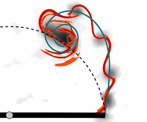





1. Introduction
The life of vortices around bluff bodies often begins with a shear layer (Jeon & Gharib Reference Jeon and Gharib2004; Fernando & Rival Reference Fernando and Rival2016; Fernando et al. Reference Fernando, Marzanek, Bond and Rival2017; Rosi & Rival Reference Rosi and Rival2017; Corkery, Babinsky & Graham Reference Corkery, Babinsky and Graham2019). When a bluff body moves relative to a fluid flow, a thin layer of fluid emerges at the edge of the body where non-zero shear flow gradients are present. This shear layer is characterised by increased values of the flow vorticity. In the wake of the body, the shear layer rolls-up and the shear layer vorticity accumulates into a coherent vortex. The interplay between the free stream or body's velocity and the induced velocity of the growing coherent vortex cause the shear layer to become curved. This curvature changes continuously in time. The roll-up of a semi-infinite shear layer or vortex sheet was first described by Kaden (Reference Kaden1931), who derived the following self-similar equation to describe the shear layer shape at any point in time  $t$
 \begin{equation} r = K(t/ \theta )^{2/3}, \end{equation}
where  $K$ is a dimensional constant, and
 $r$ and
 $\theta$ are the radial and angular coordinates along the spiral with
 $r = 0, \theta \rightarrow \infty$ at the spiral centre,
 $r\rightarrow \infty , \theta \rightarrow 0$ at the opposite end of the semi-sheet at infinity. The exponent
 $2/3$ is retrieved from dimensional analysis and the obtained curve is a spiral with tight inner turns. The initial strength of the flat sheet increases monotonically with increasing distance away from the tip of the body. For
 $t>0$, the spiral has an infinite number of turns leading to a singularity of the velocity and the sheet strength decreases to zero for
 $\theta \to \infty$ in the spiral centre. The maximum value of the sheet strength is now located somewhere along the sheet (Saffman Reference Saffman1995). In reality, viscosity will remove any singularity at the spiral centre and yield the development of a viscous core (Moore, Saffman & Stewartson Reference Moore, Saffman and Stewartson1973).
At the early stages of the roll-up, Kaden's spiral is tight with a low local radius of curvature. It accurately represents the initial evolution of the shear layer. At later stages, the radius of curvature increases due to the viscous interactions within the shear layer and between the shear layer and the coherent primary vortex that grows due to the continuous accumulation of vorticity at the centre of the spiral. The distortions can be investigated by modelling the inner portion of the spiral as a single point vortex located at the centre (Moore Reference Moore1974). The entire shear layer roll-up can also be predicted by a point-vortex representation of an initially straight vortex sheet (Krasny Reference Krasny1987; DeVoria & Mohseni Reference DeVoria and Mohseni2018). The degree of the elliptical distortions depends on the shape of the object. They are almost negligible for flat plates and become more pronounced when the edge has a non-zero wedge angle (Pullin Reference Pullin1978).
The accumulation of the vorticity in the coherent vortex in the spiral centre does not continue indefinitely. There is a physical limit to the size and the amount of circulation the primary vortex can collect (Gharib, Rambod & Shariff Reference Gharib, Rambod and Shariff1998; Mohseni & Gharib Reference Mohseni and Gharib1998; Gao & Yu Reference Gao and Yu2010; de Guyon & Mulleners Reference de Guyon and Mulleners2021). When the primary vortex is about to pinch-off, a trailing pressure maximum is observed along the shear layer (Lawson & Dawson Reference Lawson and Dawson2013). The shear layer region between the tip and the trailing pressure maximum has an adverse pressure gradient. The remaining portion of the shear layer is characterised by a positive pressure gradient. The two regions of the shear layer are now separated and the vorticity associated with the adverse pressure gradient cannot be entrained into the vortex core. The trailing pressure maximum travels downstream together with the primary vortex, causing the subsequent pinch-off of the primary vortex (Schlueter-Kuck & Dabiri Reference Schlueter-Kuck and Dabiri2016). Additional vorticity will not be entrained by the primary vortex after pinch-off and instead can accumulate into smaller secondary vortices within the trailing shear layer similar to a Kelvin–Helmholtz instability (Dabiri Reference Dabiri2009). The increases in shear layer curvature during the initial stages of the vortex formation momentarily stops when the end of the primary vortex growth is reached (Sattari et al. Reference Sattari, Rival, Martinuzzi and Tropea2012). Secondary vortices occur first between the primary vortex and the tip at locations where the sheet strength according to Kaden is maximal (Moore Reference Moore1974; Koumoutsakos & Shiels Reference Koumoutsakos and Shiels1996).
The emergence of secondary vortices seems to occur only if the Reynolds number is above a critical threshold. The value of this critical Reynolds number varies for different object geometries and boundary conditions. Critical values in a range from  $\textit {Re} = 1000$ to 3000 were observed in a cylinder wake by Wu et al. (Reference Wu, Sheridan, Hourigan and Soria1996). The lower limit was slightly higher for Bloor (Reference Bloor1964), who did not detect any instabilities for
 $\textit {Re} < 1300$. The spanwise and end configurations strongly affect the shear layer breaking behind a cylinder. Parallel and oblique vortex shedding are obtained by changing the inclination of end plates (Prasad & Williamson Reference Prasad and Williamson1997). The shear layer manifests instabilities at
 $\textit {Re} = 1200$ for parallel shedding and at
 $\textit {Re} = 2600$ for oblique shedding. The critical Reynolds number for an accelerated sharp edged plate lies in a higher range. Pullin & Perry (Reference Pullin and Perry1980) and Williamson (Reference Williamson1996) started to visually observed secondary vortices along the shear layer for
 $\textit {Re} = 4268$. This value was later confirmed by Luchini & Tognaccini (Reference Luchini and Tognaccini2002), who numerically observed the occurrence of secondary vortices in a range from
 $\textit {Re} =4500$ to 5000.
For Reynolds numbers above the critical value, series of secondary vortices appear in the trailing shear layer with a seemingly constant distance between them. The typical shear layer frequency in the wakes of cylinders is much higher than the frequency of the von Kármán vortex street. A consensus about the exact relationship between the frequency of the primary vortex shedding  ${{f}_{{K}}}$ and the secondary of shear layer vortices
 ${{f}_{{SL}}}$ has not yet been found. Bloor (Reference Bloor1964) observed that the ratio between the characteristic frequencies varies with Reynolds number according to
 ${{f}_{{K}}}/{{f}_{{SL}}} = \textit {Re}^{1/2}$. However, there is no consensus about the exponent value of the proposed relationship. Prasad & Williamson (Reference Prasad and Williamson1997) indicated that an exponent value of
 $0.67$ works for
 $\textit {Re}$ up to
 $10^5$ and Wei & Smith (Reference Wei and Smith1986) found
 $0.87$ in the range from
 $\textit {Re} = 1200$ to 11 000. No clear relationships are established in the situation of an isolated primary vortex. Based on the flow visualisation around a submerged flat plate, Grift et al. (Reference Grift, Vijayaragavan, Tummers and Westerweel2019) determined the shedding frequency of secondary vortices to lie in the range from 13 to 20 Hz, for different values of acceleration, velocity and immersion depth. This range corresponds to a Strouhal number around
 $0.2$, according to the plate geometry and kinematics used by the authors. The secondary vortex shedding frequency behind a vertical flat plate increases with increasing acceleration of the flat plate according to Rosi & Rival (Reference Rosi and Rival2017). It is crucial to define a scaling parameter, such as the Strouhal frequency for the cylinder case, that allows for a more universal relationship between the shedding frequency or formation time of primary and secondary vortices as a function of the Reynolds number.
Secondary vortices also have a practical relevance for a broad range of applications. They can create additional lift on delta wings at high angles of attack (Gad-el-Hak & Blackwelder Reference Gad-el-Hak and Blackwelder1985), cause vortex induced oscillations of solid structures that lead to fatigue damage (Shiraishi & Matsumoto Reference Shiraishi and Matsumoto1983) and lead to increased drag and noise for wing tip vortices (Birch et al. Reference Birch, Lee, Mokhtarian and Kafyeke2003). A precise prediction of secondary vortices can improve aerodynamic performance and reduce vortex induced vibrations and noise.
Here, we present an experimental study of secondary vortices generated by a rotating flat plate in a quiescent fluid. The experimental set-up is discussed in detail in the following section and is similar to the configurations used by David et al. (Reference David, Mathur, Govardhan and Arakeri2018), Corkery et al. (Reference Corkery, Babinsky and Graham2019) and Carr, DeVoria & Ringuette (Reference Carr, DeVoria and Ringuette2015). The plate is rotated with a constant rotational velocity which is varied across different experiments. The rotation of the plate generates a start up or a primary vortex. As the plate keeps rotating, the primary vortex separates and smaller secondary vortices are observed. First, we determine the critical Reynolds number above which secondary vortices are observed in the shear layer behind the tip of the rotating plate. Second, we describe the path of secondary vortices and model their path using a modified Kaden spiral. Finally, we estimate the timing of the secondary vortex shedding process and analyse the effect of the Reynolds number on the timing.
2. Experimental methods
The first series of measurements is conducted with a rectangular flat glass plate, with length  $l=8\ \textrm {cm}$, width or span
 $s=16\ \textrm {cm}$ and thickness
 $t=2\ \textrm {mm}$ that is rotated about
 $180^{\circ }$ in a water tank around its centre spanwise axis. The distance between the centre of rotation and the tip of the plate is referred to as the chord length
 $c$ here. The length of the plate is reduced to
 $l=4\ \textrm {cm}$ and the rotation point is shifted to the edge of the plate for the second set of measurements. The chord length or distance between the rotational point and the tip of the plate is preserved for both sets of experiments. For the first set of experiments, vortices are formed symmetrically behind both ends of the plate. For the second set of experiments, vortices are formed only on one end of the plate. This allows us to study the influence of the rotation point and detect potential interferences caused by symmetric vortex release on both tips when the rotation point is at mid-length. A third set of measurements with a longer plate with length
 $l=12\ \textrm {cm}$ and the rotation point at mid-length, yielding a chord length of
 $c=6\ \textrm {cm}$, was conducted to provide insight into the influence of the chord length on the vortex formation. The glass plate is stiff enough to not bend due to the interaction with water and its transparency prevents shadow regions when performing particle image velocimetry (PIV). The experiments are conducted in an octagonal tank with an outer diameter of
 $0.75\ \textrm {m}$ filled with water (figure 1a).
(a) Schematic of the experimental set-up and the rotation mechanism. (b) Trapezoidal velocity profile as a function of the angular position. The grey shaded regions indicate the portion of the motion during which the plate is accelerated.

The rotation mechanism is fastened to an outer aluminium frame such that the mid span of the plate is in the centre of the tank to limit wall interference effects. The kinematic input is given by a servo motor (Maxon RE  $35$) connected to a stainless steel shaft and transferred to the flat plate through a
 $1\!:\!1$ conical coupling. A
 $1\!:\!19$ gearbox is mounted on the motor to ensure high torque, speed and acceleration. The rotational angle, speed and acceleration are controlled via a Galil DMC-40 motion controller, which allows for accurate control of arbitrary motion profiles. The rotation programme is a trapezoidal rotational velocity profile with a fixed rotational amplitude of
 $180^{\circ }$ (figure 1b).
To ensure a continuous acceleration profile, the corners of the velocity trapezoid are smoothed. The maximum rotational speed  ${{\varOmega }_{{max}}}$ is varied from
 $30$ to
 $400^{\circ }/\textrm {s}$. This leads to a Reynolds number
 $\textit {Re} = ({{\varOmega }_{{max}}}c^2)/\nu$ ranging from 840 to 11 150. Here, ν is the kinematic viscosity of the water and the chord c is defined as the distance between the rotation point and the tip of the plate. The rotational acceleration
 $\dot {\varOmega }$ is fixed at
 $6000^{\circ }/\textrm {s}^2$.
The PIV images are recorded in the cross-sectional plane at the model mid span. A high-power pulsed light-emitting diode (LED Pulsed System, ILA 5150 GmbH) is used to create a light sheet in the measurement plane. The applicability of high-power LED for PIV has been demonstrated previously by Willert et al. (Reference Willert, Stasicki, Klinner and Moessner2010) and Krishna, Green & Mulleners (Reference Krishna, Green and Mulleners2018). Time-resolved PIV images are recorded with a Photron FASTCAM SA-X $2$ high speed camera. The camera is equipped with a 35 mm Canon lens and the camera is aligned carefully such that the optical axis of the lens is aligned with the rotational axis of the plate and is perpendicular to the light sheet (figure 1a). The frame rate and the exposure time are varied, depending on the dynamics of the motion. A frame rate and exposure time of 250 Hz and 1 ms are selected for a rotational speed of
 $30^{\circ }/\textrm {s}$. These values are 2000 Hz and 0.5 ms for the highest tested speeds. The frame rate is high enough to capture the dynamics of the motion and the LED is set to continuous mode. The camera resolution is
 $1024 \ \textrm {px}\times 1024\ \textrm {px}$, which corresponds to a field of view of
 $20\ \textrm {cm}\times 20\ \textrm {cm}$. The raw data are processed by the commercial software PIVview (PIVTEC GmbH, ILA 5150 GmbH) using a correlation model based on minimum squared differences and a multi-pass interrogation algorithm with three iterations. The final interrogation window size is
 $32\ \textrm {px}\times 32\ \textrm {px}$ with an overlap of 68 %. A third-order B-spline interpolation method for sub-pixel image shifting is performed on all passes. The resulting physical resolution is 1 mm or
 $0.025c$.
3. Results
3.1. Modelling the shear layer roll-up
At  $\textit {Re}= {840}$, the plate rotation gives rise to the formation of a primary vortex (figure 2). The vorticity fields at different angular positions are shown in the plate's frame of reference. The primary vortex is the only coherent structure that can be observed and it is connected to the plate tip through a continuous shear layer. No signs of instabilities are observed in the shear layer as the plate continues the rotation. The shear layer remains connected to the primary vortex and rolls-up around its core. As a consequence, the shear layer roll-ups into a spiral that continuously grows in time.
Vorticity fields for different angular positions (a)  $\alpha =50^{\circ }$, (b)
 $\alpha =86^{\circ }$ and (c)
 $\alpha =122^{\circ }$ for
 $\textit {Re} = {840}$. The dashed line represents the plate tip trajectory.

To trace the spiralling topology of the shear layer in the individual snapshots, we start by fitting the Kaden spiral (1.1) to the experimental data. At every time instant, the Kaden parameter  $K$ is determined such that the spiral passes through the plate's edge when the spiral centre is shifted to the instantaneous location of the primary vortex core. The location of the primary vortex core was retrieved using the dimensionless and Galilean invariant scalar function
 ${{\varGamma }_{{2}}}$ defined by Graftieaux, Michard & Grosjean (Reference Graftieaux, Michard and Grosjean2001). The resulting Kaden spirals are presented in figure 3 atop three instantaneous vorticity snapshots after a rotation of
 $\alpha =105^{\circ }$ for increasing values of the Reynolds number:
 $\textit {Re}=840,1955,8380$. The dashed lines in figure 3 indicate the plate tip trajectory since the start of the motion, the markers indicate the centre location of the primary vortex and the solid lines are the fitted Kaden spirals. For all three Reynolds numbers, the centre of the primary vortex is located on the plate tip trajectory and the fitted spirals match the rolling up shear layer well based on visual inspection. The vorticity concentration along the shear layer evolves with increasing Reynolds number from a continuous band of vorticity at
 $\textit {Re}= {840}$ (figure 3a) to an alignment of vorticity lumped into discrete vortices at
 $\textit {Re}=8380$ (figure 3c). At the intermediate Reynolds number
 $\textit {Re}={1955}$, the shear layer is undulating and some localised concentrations of high vorticity can be identified along it (figure 3b). These are signs of an unstable shear layer. When we further increase the Reynolds number to 8380, the shear layer instability becomes more prominent. The primary vortex is no longer connected to the plate tip and the shear layer is broken into a series of distinct individual structures that we refer to as secondary vortices (figure 3c). The fit of Kaden's spiral still describes well the unstable shear layer evolution and goes through the secondary vortices for the entire range of Reynolds numbers considered here.
Fit of the Kaden spiral (black solid curve) atop of instantaneous vorticity fields at  $\alpha =105^{\circ }$ for (a)
 $\textit {Re} = {840}$, (b)
 $\textit {Re} = {1955}$ and (c)
 $\textit {Re} = {8380}$. The marker
 $\ast$ indicates the top right edge of the plate and the point where the spiral ends,
 $+$ indicates the centre of the primary vortex and the point where the spiral begins. The spiral is only plotted for
 $\theta$ ranging from
 ${{\theta }_{{tip}}}$ to
 $4{\rm \pi}$. The dashed line represents the plate tip trajectory.

So far, we have merely fitted (1.1) to our experimental data at every time instant, treating Kaden's constant  $K$ as a fitting parameter. We observe that the main topology of the roll up is well captured by the Kaden spiral, but we have not yet gained any insight into the temporal evolution of the roll up or the motion of the primary vortex. If our shear layer would follow the time evolution predicted by Kaden's spiral, the obtained values for
 $K$ should be constant for all time instants. Based on the results presented in figure 4, we conclude that
 $K$ is not a constant value for our data but increases linearly in time for all Reynolds numbers. The rate of increase of
 $K$ with dimensional time decreases with increasing
 $\textit {Re}$ (figure 4a), but all curves collapse when presented in terms of the angular position of the plate (figure 4b). The angular position of the plate serves as the dimensionless time variable. It corresponds to the ratio between the travelled arc length
 $l = \varOmega t c$ and the chord length and represents a convective time scale. The chord length refers to the length between the centre of rotation and the tip of the plate.
The  $K$ parameter of Kaden's equation as a function of (a) time and (b) angular position of the plate for all the tested Reynolds numbers.

Based on these results, we propose here a modified version of the Kaden spiral to describe and predict the temporal evolution of the shear layer roll-up
 \begin{equation} r=\eta \alpha \left(\frac{\alpha}{\theta}\right)^{2/3}, \end{equation}
where  $r$ and
 $\theta$ are again the radial and angular coordinates of the spiral with respect to the spiral centre or primary vortex centre,
 $\alpha$ is the angular position of the plate and
 $\eta \alpha$ replaces the dimensional constant
 $K$ in Kaden's formulation (1.1). The value of
 $\eta$ is constant for all
 $\textit {Re}$ and is empirically determined based on the ensemble of experimental data to
 $\eta =1.02\times 10^{-2}$. The original solution of the Kaden spiral was derived for an unbound semi-infinite vortex sheet that starts out as a straight vortex sheet (Kaden Reference Kaden1931). The open end of the sheet rolls up into a vortex with the centre at
 $(r,\theta )=(0,\infty )$ and the other side of the vortex sheet is at infinity
 $(r,\theta )=(\infty , 0)$. For our experimental conditions, the vortex sheet length is finite and its length increases in time. The open end rolls up into a primary vortex. The bound end of the vortex sheet is attached to the tip of the rotating plate and only the portion of the modified Kaden spiral for
 $\theta \in [{{\theta }_{{tip}}}, \infty ]$ corresponds to our finite shear layer. Here,
 ${{\theta }_{{tip}}}$ decreases in time and indicates the bound end that is connected to the plate tip. The value of
 ${{\theta }_{{tip}}}$ is determined at every time step based solely on the observation that the primary vortex moves along a path that matches the plate tip trajectory as indicated in figure 2 by the dashed line. Based on this purely geometric constraint, we also directly obtain the radial spiral coordinate where the modified Kaden spiral meets the plate tip, indicated by
 ${{r}_{{tip}}}$, and the angular location of the primary vortex with respect to the plate, denoted by
 $\beta$. The detailed derivation of
 ${{\theta }_{{tip}}}$,
 ${{r}_{{tip}}}$, and
 $\beta$ is provided in Appendix A. With this additional information, we can now write the spatial coordinates of the spiral in the plate's frame of reference as
 \begin{gather} {{x}_{{spiral}}}= r\sin{\theta} + c \cos{\beta} \end{gather}
 \begin{gather}{{y}_{{spiral}}}={-}r\cos{\theta} + c \sin{\beta}, \end{gather}
with  $\theta$ and
 $\beta$ defined as indicated in figure 3. This modified version of the Kaden spiral is now a fully predictive model of the shear layer roll-up and the position of the primary vortex core with a single empirical constant
 $\eta$.
3.2. Validation of the model
The ability of our modified Kaden spiral to describe the roll-up of the shear layer is visually compared to the negative finite time Lyapunov exponent (nFTLE) fields corresponding to the vorticity fields presented in figure 3(a–c). The FTLE is a local measure of Lagrangian stretching of evolving fluid particle trajectories (Haller Reference Haller2001, Reference Haller2015). The maximising ridges of the negative FTLE field indicate regions along which nearby fluid particles are attracted such as the boundaries of coherent structures. The FTLE ridges provide insight into the location and growth of vortices and the flow topology (Green, Rowley & Haller Reference Green, Rowley and Haller2007; Rockwood, Huang & Green Reference Rockwood, Huang and Green2018).
At  $\textit {Re} = {840}$, the shear layer is continuous and the attracting nFTLE ridges appear as a continuous spiral. The shape and the roll-up of the spiral is well described by our predictive model (figure 5a). At
 $\textit {Re} = {1955}$, we are in a transitional regime where the shear layer is wavy and unstable (figure 3b). This observation is confirmed by the FTLE ridges, where the attracting nFTLE ridge oscillates around our predicted spiral. The deviations become larger where the spiral rolls-up (figure 5b). Finally, at
 $\textit {Re} = {8380}$, the shear layer is no longer visible in the vorticity field snapshot and we observe discrete secondary vortices instead (figure 3c). The wavelength of the nFTLE ridge fluctuations has decrease with the increase of the Reynolds number towards the discrete shedding regime. The spiral computed with (3.1) represents the middle line along which the FTLE ridge oscillates (figure 5c). We can distinguish four lobes on the outside of the predicted spiral that surround the four secondary vortices in figure 3(c). With increasing value of the Reynolds number, we can distinguish three regimes: a first regime (
 $\textit {Re} < {1500}$) which is characterised by a stable shear layer, a transitional regime (
 ${1500}<\textit {Re}<{4000}$) which is characterised by first signs of instability and a discrete vortex shedding regime (
 $\textit {Re}> 4000$) where vorticity is only observed in isolated patches. For the three
 $\textit {Re}$ regimes observed, the modified Kaden spiral is able to predict the roll-up of the shear layer and the path of the secondary vortices for the entire rotation of the plate.
Model of the shear layer roll-up (solid curve) on top of nFTLE fields at  $\alpha =105^{\circ }$ for (a)
 $\textit {Re} = {840}$, (b)
 $\textit {Re} = {1955}$ and (c)
 $\textit {Re} = {8380}$. The spiral is only plotted for
 $\theta$ ranging from θtip to
 $4{\rm \pi}$.

To further quantitatively validate our modified Kaden spiral model, we compare the measured angular locations of the primary vortex as a function of the convective time  $\alpha$ with the predicted model results in figure 6 for different
 $\textit {Re}$. The angular position
 $\beta$ of the primary vortex increases with
 $\alpha$. The relationship between
 $\beta$ and
 $\alpha$ is close to, but not entirely linear. The trajectory of the primary vortex is completely independent of the Reynolds number and is accurately predicted by the modified Kaden spiral. The trajectory is also not influenced by the total length of the plate. The measured data presented in figure 6(a) include results from the plates with the rotational location at the mid-length and from the plates with the rotational location at one end of the plate. The distance between the rotational point and the tip is the same in both cases. From the perspective of vortex formation and shear layer roll-up, a plate with a length of
 ${4}\ \textrm {cm}$ that rotates around one end is equivalent to a
 ${8}\ \textrm {cm}$ long plate rotating around its centre location. The presence of a flipped and mirrored vortex system and shear layer topology on the other side of the longer plate has no influence on the roll-up or on the trajectory of the primary vortex for the plate geometries and Reynolds numbers tested here.
Variation of the angular location of the primary vortex ( $\beta$) with convective time indicated by the plate's rotation angle (
 $\alpha$) for (a) rotations around the mid-length and rotations around the edge, both with
 $c={4}\ \textrm {cm}$; and (b) rotation around the mid-length with
 $c={6}\ \textrm {cm}$.

The influence of the distance between the rotational point and the plate tip, referred to as the chord length here, is analysed by considering a plate with length  ${12}\ \textrm {cm}$ and chord length
 ${6}\ \textrm {cm}$. For rotational motions with the longer plate, we observe the same shear layer topology for the same
 $\textit {Re}$-regimes described before. The modified Kaden spiral predictions still provide an excellent prediction of the shear layer roll-up and the trajectory of the primary vortex in figure 6(b). The angular velocity in terms of
 $\textrm {d} \beta /\textrm {d} \alpha$ is slightly increased for the higher chord length plates and a higher value of
 $\eta =1.59\times 10^{-2}$ was used for the modified Kaden spiral predictions of the larger chord length wing. For the two different chord lengths, the ratio
 $\eta /c=0.260\pm 0.005$. To take into account the influence of the chord length in our modified Kaden spiral model, we replace the empirical constant
 $\eta$ in (3.1) with
 $\eta ' c$ to obtain
 \begin{equation} r=\eta' c \alpha \left(\frac{\alpha}{\theta}\right)^{2/3}, \end{equation}
where  $\eta '=0.260$ for all data presented in this paper.
3.3. Timing of the secondary vortex shedding
In the next part, we focus our attention on the successive shedding of secondary vortices. The first step is to determine if these secondary vortices are generated from the stretching of an initially unstable shear layer or if they are discretely released after the separation of the primary vortex. Figure 7 shows the flow topology at different plate angular positions for  $\textit {Re} = {8380}$. Between
 $\alpha ={0^{\circ }}$ and
 $\alpha =30^{\circ }$ the primary vortex centre is close to the plate tip and no secondary vortices are observed. At
 $\alpha =30^{\circ }$, the primary vortex has moved away from the tip along the circular tip trajectory and a first secondary vortex forms (figure 7a). The first secondary vortex drifts towards the primary vortex core and they merge as a consequence of their mutual interaction (figure 7b). The formation and shedding of successive secondary vortices is repeated along the entire motion. Each vortex is independently formed and subsequently released from the plate tip. In this situation, the shear layer appears as a cloud of vorticity close to the plate tip from which vortices are discretely detached. Once the secondary vortices shed, they move away and are located along the modified time-varying Kaden spiral (figure 7c–e). Vortices closer to the primary vortex deviate slightly from the predicted spiralling curve only when the plate rotation is about to finish (figure 7f).
Temporal evolution of secondary vortices at different angular positions (a)  $\alpha =30.0^{\circ }$, (b)
 $\alpha =55.7^{\circ }$, (c)
 $\alpha =83.0^{\circ }$, (d)
 $\alpha =110.5^{\circ }$, (e)
 $\alpha =137.7^{\circ }$ and (f)
 $\alpha =160.0^{\circ }$ for
 $\textit {Re} = {8380}$. The black curve is the modified Kaden spiral, whose centre and end are the primary vortex centre (
 $+$) and the right top plate edge (
 $\ast$). The spiral is only plotted for
 $\theta$ ranging from θtip to
 $4{\rm \pi}$. The dashed line represents the plate tip trajectory.

The second step is to compute the timing of secondary vortices. If we consider the vorticity field, the constant presence of the cloud of vorticity close to the tip hampers the identification of the separation time. To estimate the timing of shedding of the individual vortices we use the swirling strength criterion by Zhou et al. (Reference Zhou, Adrian, Balachandar and Kendall1999). A vortex is considered a connected region where the value of the swirling strength  ${{\lambda }_{{ci}}}$ is positive. The swirling strength criteria allows us to distinguish more reliably whether a region of high vorticity concentration indicates the presence of a secondary vortex or whether it is due to a strong shear flow (see figure 8a,b). To determine the timing of release of subsequent secondary vortices, we calculate and analysed the evolution of the local average swirling strength, denoted by
 ${{\bar {\lambda }}_{{tip}}}$, in a small rectangular region close to the tip of the plate. As we are purely interested in the counterclockwise rotating structure here, we only count the positive swirling strength in regions where the vorticity is positive. The location of the probing region is indicated in figure 8(a,b) and an example of the resulting temporal evolution of the local average tip swirling strength for
 $\textit {Re}={8380}$ is presented in figure 8(c). The temporal evolution of
 ${{\bar {\lambda }}_{{tip}}}$ has a global maximum and first peak at
 $\alpha = 32.6^{\circ }$ which is followed by six clearly distinguishable smaller peaks. The initial peak corresponds to the shedding of the primary vortex, and the subsequent smaller peaks mark the shedding of individual secondary vortices. The average swirling strength systematically drops to zero in between the individual peaks, further supporting the conclusion that the secondary vortices are discretely released from the tip of the plate. The timing of the local maxima of
 ${{\bar {\lambda }}_{{tip}}}$ is used to further analyse the shedding timing of the secondary vortices. This strategy to determine the timing of secondary vortex shedding is simple yet robust and allows for a systematic and automated extraction of the timings for all measurements. The results depend slightly on the location and size of the probing region which were carefully selected based on a sensitivity analysis (Appendix B).
Snapshot of the (a) vorticity field and (b) the swirling strength at  $\alpha =115^{\circ }$ for
 $\textit {Re} = {8380}$. The black rectangle corresponds to the region in which
 ${{\bar {\lambda }}_{{tip}}}$ is computed. (c) Evolution of
 ${{\bar {\lambda }}_{{tip}}}$ as a function of the angular position of the plate. The dotted lines mark the local maxima in the average tip swirling strength. The timing of the local maxima are related to the separation angle of subsequent secondary vortices.

Results of the timing extraction strategy for  $\textit {Re} = {840}$ and
 $\textit {Re} = {1955}$ are summarised in figure 9. For the lowest Reynolds number
 $\textit {Re} = {840}$, we have a continuous stable shear layer and the associated snapshot of the swirling strength at
 $\alpha =100^{\circ }$ in figure 9(a) shows a single isolated coherent structure and no sign of secondary vortices. This is confirmed by the time evolution of
 ${{\bar {\lambda }}_{{tip}}}$ (figure 9a) that exhibits a single peak at
 $\alpha =31.9^{\circ }$. No other peaks are observed afterwards confirming that the shear layer is a continuous layer of fluid without the presence of any instabilities for this Reynolds number. For the intermediate Reynolds number
 $\textit {Re} = {1955}$, the shear layer topology appeared to be undulating with some localised concentrations of high vorticity along it (figure 3b). The temporal evolution of the average tip swirling strength reveals the shedding of two secondary coherent structures formed after the primary vortex (figure 9b). These two structures are formed and released from the tip and they are not formed afterwards due to the stretching of the shear layer which does not become clear based solely on the vorticity flow topology.
Snapshots of the (a,d) vorticity field and (b,e) swirling strength at  $\alpha =100^{\circ }$ and (c,f) evolution of
 ${{\bar {\lambda }}_{{tip}}}$ as a function of the angular position of the plate. The first row corresponds to
 $\textit {Re} = {840}$ at which the shear layer appears continuous. The second row is for
 $\textit {Re} = {1955}$ at which the shear layer shows signs of instability.

The experiments are repeated five times at each Reynolds number. The separation time and angle of successive secondary vortices are computed and analysed for all experiments with  $\textit {Re}>4000$ corresponding to the discrete shedding regime. The timing of the secondary vortex shedding versus the number corresponding to the order of successive shedding is presented in figure 10. In general, the time interval between successive vortices increases the more secondary vortices have been released and the time interval decreases with increasing Reynolds number, yielding a larger total number of secondary vortices at the end of the
 $180^{\circ }$ plate rotation. If we hypothesise that the strength of the secondary vortices remains approximately constant, which is confirmed by the experimental data, then the increase in time interval should be due to a decrease in the circulation feeding rate by the shear layer. This feeding rate is related to the shear rate of at the tip of the plate and can be estimated by
 \begin{equation} \frac{\textrm{d} \varGamma}{\textrm{d} t}\propto\frac{{{v}_{{out}}}^2-{{v}_{{in}}}^2}{2}\approx\frac{(\varOmega c)^2 - {{v}_{{in}}}^2(t)}{2}, \end{equation}
where  ${{v}_{{out}}}$ refers to the velocity at the outer side of the shear layer, which equals the tip velocity
 $\varOmega c$ and
 ${{v}_{{in}}}$ refers to the velocity at the inner side of the shear layer. The velocity at the inner side
 ${{v}_{{in}}}$ is close to zero during the initial part of the rotation as the plate rotates in a quiescent fluid and increases due to the accumulation of vortex induced velocity components along the direction of the plate's motion. The feeding rate thus decreases when the rotational velocity and the Reynolds number decrease and when the induced velocity due to an increased number of released vortices. This explains the general trends observed in figure 10(a,b).
Delay between the successive shedding of secondary vortices in terms of (a) dimensional time and (b) convective time or angular distance between secondary vortices as of the shedding order  $n$. The solid lines are the fit of the angular distance between vortices and
 $n$. (c) Coefficient
 $\Delta \alpha$ as a function of the maximum rotational speed of the plate.

To quantify the evolution of the shedding timing of the secondary vortices, we fit the measured values in figure 10(b) with a power law in the form
 \begin{equation} \alpha(n) = {{\alpha}_{{0}}}(1+\Delta\alpha)^n, \end{equation}
where  ${{\alpha }_{{0}}}$ and
 $\Delta \alpha$ are fitting constants and
 $n$ counts the number of secondary vortices. This power law is suitable to represent the timing dynamics for all Reynolds numbers as all fits have a value of the coefficient of determination
 $R^2$ above
 ${99}\,{\%}$. The fitting parameter
 $\Delta \alpha$ indicates the relative increase in
 $\alpha$ between the convective timing of successive secondary vortices, i.e.
 ${{\alpha }_{{n+1}}}/{{\alpha }_{{n}}}=1+\Delta \alpha$. A higher value of
 $\Delta \alpha$ indicates a larger delay between successive vortices and a lower total number of vortices shed at the end of the motion. The evolution of
 $\Delta \alpha$ as a function of the maximum rotational speed is presented in figure 10(c). The results confirm the general decrease in the time delay between the release of subsequent vortices for increased rotational velocity of the plate which yields an increased feeding rate according to (3.6).
4. Conclusion
The roll-up of a shear layer behind a rotating plate in a quiescent fluid is experimentally studied for different rotational velocities or Reynolds numbers. Particular focus was directed towards the formation, trajectory, and timing of secondary vortices.
Based on the time-resolved PIV, we identified three Reynolds number regimes based on the stability of the shear layer. For  $\textit {Re} < {1500}$, a stable shear layer in the form of a continuous band of vorticity is observed that rolls up into a single coherent primary vortex. For
 $\textit {Re} > {4000}$, the shear layer is unstable and secondary vortices are discretely released from the plate's tip during the rotation. In the intermediate regime for
 ${1500} <\textit {Re} < {4000}$, first signs of instability appear. The shear layer is still a continuous band of vorticity but it shape is wavier and localised concentrations of higher vorticity emerge. In all three regimes, the centre of the primary vortex is located on the plate tip trajectory and the shear layer topology matches a spiral shape similar to the roll up of a free shear layer. A modified version of the Kaden spiral is proposed to describe and predict the temporal evolution of the shear layer roll up. The key modification is the replacement of the constant dimensional Kaden constant
 $K$ by a factor
 $\eta 'c\alpha$ that increases linearly with the rotational angle of the plate and takes into account the effect of the chord length. A single value of
 $\eta '$ has been empirically determined for all experimental conditions presented in this paper. The proposed modified Kaden spiral model describes the spatio-temporal evolution of the shear layer and accurately predicts the trajectory of the centre of the primary vortex for all Reynolds numbers and different plate dimensions.
The timing of secondary vortices shedding for Reynolds numbers in the discrete shedding regimes is determined using the swirling strength criterion. The swirling strength fields confirm that secondary vortices form directly at the tip of the plate and not further downstream due to the stretching of the shear layer. The separation time of each secondary vortex is identified as a local maximum in the temporal evolution of the average swirling strength close to the plate tip.
The time interval between the release of successive vortices is not constant during the rotation but increases the more secondary vortices have been released. The shedding time interval also increases with decreasing Reynolds number, yielding a lower total number of secondary vortices at the end of the  $180^{\circ }$ plate rotation for lower
 $\textit {Re}$. The increased time interval under both conditions is due to a reduced circulation feeding rate.
Declaration of interests
The authors report no conflict of interest.
Appendix A. Derivation of the modified Kaden spiral
The modified version of the Kaden spiral we propose takes into account the temporal increase in the distance between the primary vortex and the tip of the plate where the bound end of the vortex sheet is fixed. The angular coordinate along the spiral that marks the bound end of the vortex sheet is denoted by  ${{\theta }_{{tip}}}$. The value of
 ${{\theta }_{{tip}}}$ is determined at every time step based solely on the observation that the primary vortex moves along a path that matches the plate tip trajectory. Based on this purely geometric constraint, we also directly obtain the radial spiral coordinate where the modified Kaden spiral meets the plate tip, indicated by
 ${{r}_{{tip}}}$, and the angular location of the primary vortex with respect to the plate, denoted by
 $\beta$. Their detailed derivation is given here.
We consider the flow situation after the plate has rotated for a given  $\alpha$ in the plates frame of reference in figure 11. The plate tips trajectory is indicated by the dashed line. The primary vortex is located on that circular trajectory. Its angular position with respect to the plate's centre of rotation and tip is indicated by
 $\beta$.

Consider that we have shifted the modified spiral defined by (3.4) such that the spiral centre ( $r=0,\theta \rightarrow \infty$) is located in the centre of the primary vortex. The radial and angular location of the plate tip in the spiral coordinates are given by (
 ${{r}_{{tip}}}, {{\theta }_{{tip}}}$) as indicated in figure 11. For a given spiral form, there is only one solution for
 $\beta$ that allows the spiral to go through the plate tip. This solution can be found by ensuring that the trigonometric relationships for the two triangles outlined in figure 11(b) are met
 \begin{gather} \beta = 2\arcsin ({{r}_{{tip}}}\cos {{\theta}_{{tip}}}/2c) \end{gather}
 \begin{gather}\beta = \arcsin({{r}_{{tip}}}\cos {{\theta}_{{tip}}}/c). \end{gather}
The distance between the primary vortex centre and the tip of the plate,  ${{r}_{{tip}}}$, is determined through the modified Kaden spiral (3.4), for
 $\theta = {{\theta }_{{tip}}}$. In this way, (A1) and (A2) are only functions of
 ${{\theta }_{{tip}}}$, which is computed by equalising the two relationships. For
 $\beta > {\rm \pi}/2$, we need to use
 \begin{equation} \beta = {\rm \pi}- \arcsin({{r}_{{tip}}}\cos {{\theta}_{{tip}}}/c) \end{equation}
instead of (A2). Once  ${{\theta }_{{tip}}}$ is retrieved, we substitute it into (A1) to obtain the angular position
 $\beta$ of the primary vortex. From the value of
 $\beta$, we compute the Cartesian coordinates of the primary vortex centre, which corresponds to the centre of our predicted spiral model. The full spiral is finally obtained for every plate angular position
 $\alpha$, using (3.2) with
 $\theta \in [{{\theta }_{{tip}}}, \infty ]$.
Appendix B. Sensitivity analysis of the location and size of the average tip swirling strength probing region
The local average swirling strength  ${{\bar {\lambda }}_{{tip}}}$ reaches a local maximum value when most of the vortex fills the selected rectangular region. If the position and dimension of the rectangular region is not properly set, the identification of the separation time through local peaks loses accuracy. We perform a sensitivity analysis of the best position and dimension of the rectangular region. The first thing to set is the centre of the rectangle. We observed that when the core centre of a secondary vortex is approximately 1 cm above the plate tip, the following secondary vortex starts growing. Since the trajectory of each secondary vortex is predicted by the modified Kaden spiral (3.4), we decide to place the centre of the rectangle along the spiral, 1 cm above the tip. The area of the rectangle has to be big enough to fully include the vortex but it does not have to include the swirling strength associated with the plate and to the other secondary vortices. For the plate chord
 $c = 4\ \textrm {cm}$, a rectangle base of
 $0.25c$ is sufficiently large to include the radial dimension of the secondary vortex, excluding the swirling strength of the plate. A height of
 $0.15c$ allows to have one secondary vortex at a time in the selected rectangle.


 Open access

