I. INTRODUCTION
Residual stresses are of practical importance in bulk materials and coatings, which critically affect their mechanical integrity and reliability. Residual stress is that which remains in a body that is stationary and at equilibrium with its surroundings. It can be very detrimental to the performance of a material or the life of a component. Alternatively, beneficial residual stresses can be introduced deliberately. For instance, for a structural component undergoing an applied stress, the compressive residual stress enhances the resistance to crack propagation, whereas tensile residual stress reduces the resistance. For semiconductor devices, residual stresses may decrease their service life sharply; however, with the use of internal stresses, it is possible to considerably increase the mobility of charge carriers and thus the charge speed of the device can be increased markedly. Residual stresses are more difficult to predict than the in-service stresses on which they superimpose. For this reason, it is important to have reliable methods for the measurement of these stresses and to understand the level of information they can provide.
The conventional methods for measuring residual stresses can be divided into two groups: mechanical stress-relaxation methods (including hole-drilling and saw-cutting techniques) Reference Tebedge, Alpsten and Tall1,Reference Nelson and McCrickerd2 and physical-parameter analysis methods (including ultrasonic wave, magnetic Barkhausen noise, x-ray, and neutron diffraction). Reference Gauthier, Krause and Atherton3–Reference Hu, He and Chen5 However, these methods mentioned here have their own shortcomings. For example, the destructive nature of mechanical stress-relaxation methods limits the wide application of these techniques in industry, and it is difficult to separate intrinsic microstructural effects on the physical parameters from the effects of a residual stress in physical-parameter analysis methods.
Another technique for the measurement of residual stress is the instrumented indentation; it has rapidly emerged as a powerful tool for exploring mechanical behavior of a small volume in the past two decades. The instrumented indentation makes it possible to measure a variety of mechanical properties (e.g., hardness, Reference Doerner and Nix6,Reference Oliver and Pharr7 Young's modulus, yield strength, Reference Field and Swain8,Reference Swain9 and work-hardening exponent Reference Dao, Chollacoop, Van Vliet, Venkatesh and Suresh10 ) and small-scale mechanical behavior only by analyzing the indentation load–displacement (P–h) curve. More recently, many studies have been undertaken to develop new ways for measuring residual stress using instrumented indentation, Reference Suresh and Giannakopoulos11–Reference Gerbig, Stranick and Cook14 because this nondestructive/mechanical technique can overcome the limitations of conventional methods. However, the current indentation method cannot be applied to a material showing a strong dependence of the residual stress on its direction while the indenters basically give an average response of the surface residual stress. Residual stress states determined by current instrumented indentation techniques are mostly restricted to the equi-biaxial or uniaxial stress. Reference Swadener, Taljat and Pharr15 Although some models Reference Lee and Kwon16 provide general residual stress solutions, the stress ratio should be known independently. An admirable effort has been made by Lee et al. Reference Lee, Takashima, Higo and Kwon17 to obtain the ratio of two principal stresses by measuring the pile-up height ratio, but the direct relation between residual stress and pile-up displacement is not given. More recently, some attempts have been made using an asymmetric Knoop indenter, Reference Kwon, Lee, Han, Lee, Lee, Choi and Kim18 but the method has not been fully established yet. Therefore, determination of the magnitude and direction of residual stress with general stress state is one of the key issues remained unresolved.
For measuring material properties by load and depth sensing indentation methods, it is essential that the contact geometry is established precisely since analysis procedures used for determining properties like the hardness, H, and elastic modulus, E, rely heavily on an accurate measurement of the contact area. Reference Oliver and Pharr7 However, the measurement of the contact area from the load–depth data is not a straightforward process, as it depends on the pile-up or sink-in of material around the contact impression. Bolshakov and Pharr Reference Bolshakov and Pharr19 examined the significance of pile-up for rigid conical indenters and found that if pile-up is neglected, the true contact area can be underestimated by as much as 60%, leading to similar errors in calculated material properties. Thus, a complete understanding indentation of pile-up and sink-in is crucial to make accurate property measurements.
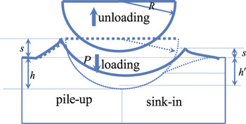
For spherical indenters, the pile-up and sink-in geometry may change significantly during indentation by virtue of the transition from purely elastic deformation at small depth to plastically dominated behavior at large depth. The contact geometry for spherical indentation is illustrated in Fig. 1, which shows a rigid sphere of radius R driven into a material by a force P to a penetration depth h. The right-hand side of the figure shows the behavior when material sinks in and the left-hand side shows pile-up. When the pressure on the indenter is removed, the contact impression will partially recover due to elastic processes. The indentation depth h will recover to h′, the pile-up will increase and the sink-in will convert to pile-up after unloading for some material. The permanent deformation was rarely considered in previous literature. Reference Khan, Hainsworth, Fitzpatrick and Edwards20,Reference Kim, Lee, Choi and Kwon21
Spherical indentation contact geometry.

Underwood Reference Underwood22 introduced an optical-interference method to observe the permanent surface deformation around an indentation in steel. The results implied that the direction and amplitude of residual stress are dependent on the deformation around an indentation after unloading.
In this work, a novel experimental method is put forward for solving the problems aforementioned during the measurement of residual stress in the condition of both uniaxial and biaxial stress. The directionality and magnitude of surface stress were scrutinized from nonsymmetrical morphology of spherical indenting deformation on artificially strained specimen which was set on a biaxial stress tester. Different applied nonequibiaxial stress can make different pile-ups along two principle orthogonal straining axes. Through experimental studies, it is found that the direction and magnitude of the principle residual stress can be determined by measuring the pile-ups along these two directions after unloading.
II. EXPERIMENTAL DETAILS
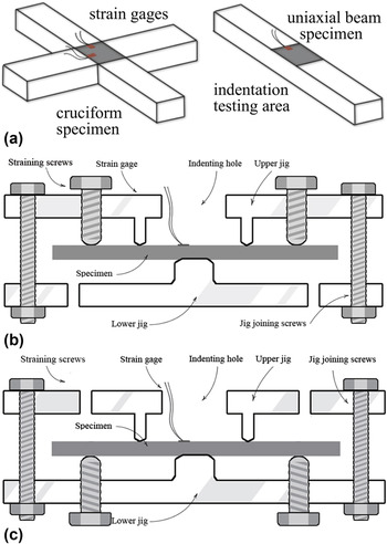
The material used in this study was 45# steel, which has the mechanical properties of elastic modulus 210 GPa, Poisson's ratio 0.33, and yield strength 375 MPa at room temperature. The 8-mm-thick rectangular beam and cross-shaped specimens [see Fig. 2(a)] were machined from a thick plate and heat-treated to remove internal stress. No warping was detected at the specimen after the stress-relief annealing. The specimen surface was mechanically ground with roughness of 0.2 μm for the subsequent instrumented indentation tests. The artificially residual stress was applied by the bending fixture [see Figs. 2(b) and 2(c)], the device is followed by Bisrat Reference Bisrat and Roberts23 and Lee. Reference Lee and Kwon16 The screws can provide both tensile and compressive residual stress, and the artificially residual stress was measured by strain gages.
(a) The cross-shaped specimen and the uniaxial specimen (b) the fixture providing tensile residual stress (c) the fixture providing compressive residual stress.

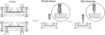
The process of the experiment can be divided into three steps: the first step is the application of residual stress, including uniaxial residual stress and biaxial residual stress; the second step is the Brinell indentation test; the last step is the profile measurement after unloading. The experimental procedures are shown in Fig. 3.
The experimental procedures.

When the screws in the upper jig are tightened, the fixture is a three-point bender, it can provide tensile residual stresses. And when the screws in the lower jig are tightened, it is a four-point bender, the fixture can provide compressive residual stresses. To keep the applied strain below the elastic limit, the difference in two orthogonal principal strain components was maintained below the specimen yield strain according to the Tresca yield criterion. Once the residual stresses had been applied on the specimen, the indentation tests were carried out using the Brinell indenter with diameter of 2.5 mm. The shadow area of the specimen was chosen to be made an indentation under a constant press force of 1837 N. The press force remained for 30 s, and then unloaded. The indenter left a permanent deformation on the tested specimen. The deformations are different between the unstressed specimen and the specimen with residual stress. The permanent deformations after unloading were measured with an optical measurement system.
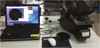
The morphologies of the remnant impression after unloading were observed using a laser confocal system (VK-X200, made by Keyence, in Osaka, Japan) with a resolution of 20 nm, see Fig. 4, appropriate magnification should be chosen to ensure the high resolution and make the all target in the field of vision. The cross-sectional impression profiles were measured along radial lines parallel to the two orthogonal loading axes. The Brinell indentations were also carried out on the unstressed specimen to compare their deformation patterns with those of the stressed specimen.
The laser confocal system.

III. RESULTS AND DISCUSSION
A. Brinell indentation deformation measurement
The indentation on the unstressed specimen invoked a peak penetration depth 96.2 ± 0.2 μm and remnant circular impression 1284 ± 2.0 μm in diameter. Local surface near the impression is bulged and its detailed morphologies, observed from the lateral directions, show a circular-like symmetric pile-up deformation. The maximum pile-up is proposed as the parameter for describing a degree of the material accumulation.
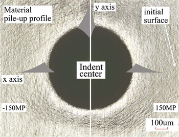
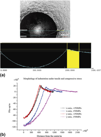
The morphologies of the uniaxial specimen under tensile stress of 150 MPa and compressive stress of 150 MPa are shown in Fig. 5. The direction of the stress is along x-axis, which is parallel to the horizontal direction, “−” means compressive and “+” means tensile. Thus the pile-up height is used as an empirical parameter in subsequent experiments, describing the surface morphology of the remnant indentation. The distributions of pile-up are similar with the previous simulation results, Reference Shen, He, Liu, Gong, Zhang and Lei24 and they are also in accordance with Underwood's results Reference Underwood22 in the optical interference experiment. The detailed indentation pile-up is shown in Fig. 6, Fig. 6(b) shows the different pile-ups along x and y axes under tensile and compressive residual stress. From the figure, it can be observed that the pile-up along x-axis is larger than that along y-axis in the condition of uniaxial tensile residual stress. On the contrary, the pile-up of y-axis is larger than that of x-axis in the condition of uniaxial compressive residual stress.
Compressive stress specimen (left) and tensile stress specimen (right), measured by VK-200, Keyence series.

(a) The pile-up measured by microscope system (b) morphology of indentation under tensile and compressive stress.

B. A dependency of pile-up on magnitude of applied stress
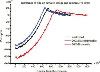
The distribution of pile-up along the direction (x axis) of residual stress in the condition of uniaxial tensile and compressive stress with ±200 MPa is shown in Fig. 7. It can be seen that the tensile stress makes the pile-up decrease and the compressive stress makes it increase.
The distribution of pile-up along the direction of residual stress under uniaxial stress state.

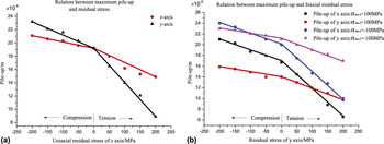
By changing the magnitude of applied uniaxial stress before indentation tests, one can obtain the distribution of pile-up along x and y axes with different uniaxial residual stresses, which suggests a bilinear relationship, as shown in Fig. 8(a). The pile-up displacements along both x-axis and y-axis decrease with the increase of uniaxial residual stress. There is an inflection point from compressive to tensile residual stress, i.e., the rate of change of pile-up is different between tensile and compressive conditions.
The experimental fitting results between pile-up and residual stress (a) uniaxial residual stress (b) biaxial residual stress.

As for biaxial residual stress states, the residual stress along x-axis is set as 100 MPa or −100 MPa, and the residual stress along y-axis varies from −200 MPa to 200 MPa, the increment of which is 50 MPa. And then the indentation tests and pile-up measurements are carried out.
If the residual stress along x-axis is the same as the stress along y-axis, it is the equi-biaxial residual stress. The pile-ups of x-axis and y-axis are also equal. When the stress of y-axis is larger than that of x-axis, the maximum pile-up appears in y-axis. However, when the stress of x-axis is larger than that of y-axis, the maximum pile-up appears in x-axis. From the features, the position of the biaxial residual stress can be easily recognized. Generally, the maximum pile-up appears on the direction of the maximum residual stress component.
Pick out the maximum pile-ups of both x and y axes from the above results, the relationship between the biaxial residual stress and the maximum pile-ups along x and y axes can be obtained and shown in Fig. 8(b). They are also bilinear relationships.
C. A general function of pile-up and residual stress
From the experiments with different combinations of biaxial residual stress, we obtain a relationship between the maximum pile-up after unloading and the biaxial residual stress as follows:
 $$\matrix{ {{s_x} = a{\sigma _{{\rm{res - }}x}} + b{\sigma _{{\rm{res - }}y}} + c\quad ,} \cr {{s_y} = b{\sigma _{{\rm{res - }}x}} + a{\sigma _{{\rm{res - }}y}} + c\quad ,} \cr}$$
where σres-x is the residual stress of x axis, σres-y is the residual stress of y axis, s x is the maximum pile-up of x axis, and s y is the maximum pile-up of y axis. The constants a, b, c are obtained from the fitting curves. The values of a are 0.0095 for compressive residual stress and 0.0215 for tensile residual stress, the values of b are 0.02 for compressive residual stress and 0.0515 for tensile residual stress, and c = 19.2 μm, namely s 0, which means the pile-up of unstressed specimen.
Before determining biaxial residual stress by using Eq. (1), the full-field pile-up displacements after unloading should be measured firstly. Due to the symmetry, there are two maximum pile-up displacements. The direction of the connecting line of these two maximum pile-ups is the direction of the maximum residual stress component, and the vertical line of this connecting line corresponds to the minimum residual stress component. The values of coefficients a and b should be correctly selected according to the state of residual stress components. According to the facts that the tensile residual stress makes the pile-up increase and tensile residual stress decreases it, we can determine residual stress components in the tensile or compression state with help of different amplitude of pile-ups. The analyzed results are listed in Table I (“−” means compressive and “+” means tensile).
Signs of σres-x and σres-y determined by pile-ups.

Based on the above results, the direction and amplitude of the biaxial residual stress can be determined by measuring the pile-up displacement around an indentation after unloading. The variation of pile-up for a unit variation of stress is very small, especially for compressive residual stress. The sensitivity and accuracy of this method mainly depend on the resolution of the optical measuring system. From Eq. (1), we have
 $$\Delta {s_x} = a\Delta {\sigma _{{\rm{res - }}x}} + b\Delta {\sigma _{{\rm{res - }}y}}\quad .$$
The resolution of the confocal microscopy system used in the experiment is 20 nm, and then the resolution of residual stress is about 2.1 MPa. This method is effective, and the sensitivity can satisfy the requirement in the material with low roughness.
IV. CONCLUSION
A novel experimental study is performed on the prediction of two principal components in a biaxial surface stress through the spherical indentations on artificial stresses applied in steel specimens. The stress dependency of remnant impression morphology is investigated by measuring the variations in pile-up heights along two principal axes. As a result, the direction and the amplitude of the residual stress are determined by measuring the maximum pile-up displacement around an indentation after unloading, which suggests a bilinear relation. The sensitivity of the method proposed here depends on the accuracy of the measurement of pile-ups. Furthermore, a general function between pile-ups and residual stresses is derived from the empirically fitted relationship.
The method proposed here is useful but still has some limitations at present step, which will be the purposes of following studies. The change of the pile-up is too slow compared to that of the residual stress. The low sensitivity of the pile-up hindered its application for low surface stress and large roughness.
ACKNOWLEDGMENTS
This work was financially supported by the NSFC (Nos 11272131, 11472114).