1 Introduction
Much work has been done on the study of hydraulic jumps in a divergent radial flow (Liu & Lienhard Reference Liu and Lienhard1993; Bush & Aristoff Reference Bush and Aristoff2003; Ray & Bhattacharjee Reference Ray and Bhattacharjee2007; Kasimov Reference Kasimov2008; Andersen, Bohr & Schnipper Reference Andersen, Bohr and Schnipper2010; Teymourtash, Khavari & Passandideh-Fard Reference Teymourtash, Khavari, Passandideh-Fard, Nouri-Borujerdi and Movahhedi2010; Eyo, Joshua & Udoh Reference Eyo, Joshua and Udoh2011; Martens, Watanabe & Bohr Reference Martens, Watanabe and Bohr2012; Labousse & Bush Reference Labousse and Bush2013; Rojas, Argentina & Tirapegui Reference Rojas, Argentina and Tirapegui2013). Such a flow can easily be created by the vertical impact of a jet of water on a solid flat surface. After the impact, the flow spreads radially outwards and at some distance from the point of impingement an abrupt depth transition occurs (a hydraulic jump appears). Despite the radial symmetry of the initial flow and corresponding boundary conditions, the hydraulic jump is not necessarily circular: its shape can even have a polygonal structure with sharp corners (see Ellegaard et al. (Reference Ellegaard, Hansen, Haaning, Hansen, Marcussen, Bohr, Hansen and Watanabe1998, Reference Ellegaard, Hansen, Haaning, Hansen, Marcussen, Bohr, Hansen and Watanabe1999), Bush, Aristoff & Hosoi (Reference Bush, Aristoff and Hosoi2006)).
An interesting experimental study for convergent radial flows was recently performed by Foglizzo et al. (Reference Foglizzo, Masset, Guilet and Durand2012, Reference Foglizzo, Kazeroni, Guilet and Masset2015). A radial symmetry breaking was also observed: under some flow conditions a rotating singular point (a cusp) appears at the front of the hydraulic jump.
A reliable mathematical model which is capable of capturing this complex phenomenon of symmetry breaking is still lacking. The aim of this article is to model such a phenomenon by using the model of shear shallow water flows (Teshukov Reference Teshukov2007; Richard & Gavrilyuk Reference Richard and Gavrilyuk2012, Reference Richard and Gavrilyuk2013). Shear effects are necessary to describe surface rollers of the hydraulic jump. In the one-dimensional (1D) case, such a model complemented by friction terms was used for the study of travelling waves down inclined planes (roll waves) and turbulent hydraulic jumps. A strong physical adequacy of the model with the experimental observations was found (Richard & Gavrilyuk Reference Richard and Gavrilyuk2012, Reference Richard and Gavrilyuk2013; Richard Reference Richard2013; Ivanova et al. Reference Ivanova, Gavrilyuk, Nkonga and Richard2017). The classical Saint-Venant equations are not able to predict these phenomena, because they do not take into account vorticity effects. The new model was able to form rollers in the hydraulic jumps through the Rankine–Hugoniot relations for the corresponding hyperbolic and conservative equations. In particular, the model was able to describe the hydraulic jump shape as well as jump toe oscillations appearing when the Froude number is larger than approximately 1.5. A natural step would be to apply this model for the description of multi-dimensional turbulent hydraulic jumps, and, in particular, to see if the model of shear shallow water flows is able to describe the breaking of radial symmetry in hydraulic jumps observed experimentally.
The governing equations are obtained by depth averaging of the multi-dimensional Euler equations (Teshukov Reference Teshukov2007; Richard & Gavrilyuk Reference Richard and Gavrilyuk2012, Reference Richard and Gavrilyuk2013). The hypothesis of weakly sheared flows allows us to keep the second-order depth-averaged correlations in the governing equations but neglect the third-order correlations, and thus to close the governing system in the dissipationless limit.
The corresponding multi-dimensional model of shear shallow water flows is a hyperbolic system of equations which is reminiscent of generic Reynolds-averaged Euler equations for barotropic turbulent flows. The model has three families of characteristics, corresponding to the propagation of surface waves, shear waves and average flow. The main difficulty is the non-conservativity of the governing equations: for six unknowns (the fluid depth, two components of the depth-averaged horizontal velocity, and three independent components of the symmetric Reynolds stress tensor) one has only five conservation laws: conservation of mass, momentum, energy and mathematical ‘entropy’. The last one determines the evolution of the determinant of the Reynolds stress tensor. The non-conservative nature of the multi-dimensional equations represents an enormous difficulty from the mathematical and numerical point of view. The definition and computation of discontinuous solutions for non-conservative hyperbolic equations is a challenging problem. Recently, a new numerical method based on Cartesian meshes was developed for this non-conservative system (Gavrilyuk, Ivanova & Favrie Reference Gavrilyuk, Ivanova and Favrie2018a ). In the present work we extend this technique to polar coordinates.
Another difficulty is to introduce the dissipative terms into a model that still remains an empirical procedure. In particular, in Gavrilyuk et al. (Reference Gavrilyuk, Ivanova and Favrie2018a ) we introduced dissipative terms which ensure the positive definiteness of the Reynolds stress tensor. Also, in the 1D limit we recovered the dissipation law developed in Richard & Gavrilyuk (Reference Richard and Gavrilyuk2013). In particular, this dissipation law allowed us to describe the ‘fingering’ phenomenon (i.e. the formation of transverse waves on the front of roll waves). We will also test here another type of dissipation law used earlier in Gavrilyuk, Liapidevskii & Chesnokov (Reference Gavrilyuk, Liapidevskii and Chesnokov2016) to study surface wave propagation in shear flows.
Different dissipation laws give us different flow patterns. The first type of dissipation law gives us hydraulic jumps with the formation of a rotating cusp at the front of the hydraulic jump, as in the experiments by Foglizzo et al. (Reference Foglizzo, Masset, Guilet and Durand2012). The second type of dissipation law gives us an unusual square-like hydraulic jump. This square-like jump has no sharp corners and rotates at a constant velocity. This is different from the sharp corner structures of hydraulic jumps obtained in divergent radial flows (Ellegaard et al. Reference Ellegaard, Hansen, Haaning, Hansen, Marcussen, Bohr, Hansen and Watanabe1998, Reference Ellegaard, Hansen, Haaning, Hansen, Marcussen, Bohr, Hansen and Watanabe1999).
The structure of the article is organized as follows. In § 2 the ‘shear shallow water’ equations are presented. Two types of dissipative source term are proposed in § 3. Experimental works are briefly discussed in § 4. The governing equations of shear flows rewritten in polar coordinates, and the corresponding initial and boundary conditions are presented in §§ 5, 6. The numerical results are discussed in § 7. In appendix A, the numerical scheme for the non-conservative equations is written in polar coordinates.
2 Two-dimensional (2D) shear shallow water flows
The system describing multi-dimensional shear shallow water flows over a flat bottom without friction effects can be written in the form (Teshukov Reference Teshukov2007; Gavrilyuk & Gouin Reference Gavrilyuk and Gouin2012; Richard & Gavrilyuk Reference Richard and Gavrilyuk2012, Reference Richard and Gavrilyuk2013)
 $$\begin{eqnarray}\left.\begin{array}{@{}c@{}}\displaystyle \frac{\unicode[STIX]{x2202}h}{\unicode[STIX]{x2202}t}+\text{div}\left(h\boldsymbol{U}\right)=0,\\ \displaystyle \frac{\unicode[STIX]{x2202}\left(h\boldsymbol{U}\right)}{\unicode[STIX]{x2202}t}+\text{div}\left(h\boldsymbol{U}\otimes \boldsymbol{U}+\displaystyle \frac{gh^{2}}{2}\unicode[STIX]{x1D644}+h\unicode[STIX]{x1D64B}\right)=\mathbf{0},\\ \displaystyle \frac{\text{D}\unicode[STIX]{x1D64B}}{\text{D}t}+\frac{\unicode[STIX]{x2202}\boldsymbol{U}}{\unicode[STIX]{x2202}\boldsymbol{x}}\unicode[STIX]{x1D64B}+\unicode[STIX]{x1D64B}\left(\frac{\unicode[STIX]{x2202}\boldsymbol{U}}{\unicode[STIX]{x2202}\boldsymbol{x}}\right)^{\text{T}}=\mathbf{0}.\end{array}\right\}\end{eqnarray}$$
The system is obtained by averaging the incompressible Euler equations over the fluid depth and using the hypothesis of smallness of the horizontal vorticity (weakly sheared flows). Here
 $t$
is the time,
 $\boldsymbol{x}=(x,y)^{\text{T}}$
are the Cartesian coordinates,
 $h$
is the fluid depth,
 $g$
is the gravity,
 $\boldsymbol{U}=(U,V)^{\text{T}}$
is the depth-averaged horizontal velocity,
 $\text{D}/\text{D}t$
means the material derivative with respect to the mean motion
 $$\begin{eqnarray}\frac{\text{D}}{\text{D}t}=\frac{\unicode[STIX]{x2202}}{\unicode[STIX]{x2202}t}+\boldsymbol{U}^{\text{T}}\unicode[STIX]{x1D735},\end{eqnarray}$$
 $\unicode[STIX]{x1D64B}=\unicode[STIX]{x1D64B}^{\text{T}}$
is the symmetric stress tensor which measures the distortion of the instantaneous horizontal velocity profile
 $\tilde{\boldsymbol{U}}(t,x,y,z)$
, which depends a priori on the vertical coordinate
 $z$
. The definitions of
 $\boldsymbol{U}$
and
 $\unicode[STIX]{x1D64B}$
are as follows:
 $$\begin{eqnarray}\boldsymbol{U}=\frac{1}{h}\int _{0}^{h}\tilde{\boldsymbol{U}}(t,x,y,z)\,\text{d}z,\quad \unicode[STIX]{x1D64B}=\frac{1}{h}\int _{0}^{h}(\tilde{\boldsymbol{U}}-\boldsymbol{U})\otimes (\tilde{\boldsymbol{U}}-\boldsymbol{U})\,\text{d}z.\end{eqnarray}$$
The tensor
 $\unicode[STIX]{x1D64B}$
is positive definite. The positive definiteness of
 $\unicode[STIX]{x1D64B}$
is a consequence of the Cauchy–Schwarz inequality. The sign
 $\otimes$
means the tensor product and
 $\unicode[STIX]{x1D644}$
is the identity tensor. Equations (2.1) admit the energy conservation law
 $$\begin{eqnarray}\frac{\unicode[STIX]{x2202}}{\unicode[STIX]{x2202}t}\left\{h\left(\frac{1}{2}|\boldsymbol{U}|^{2}+e_{i}+e_{T}\right)\right\}+\text{div}\left\{h\boldsymbol{U}\left(\frac{1}{2}|\boldsymbol{U}|^{2}+e_{i}+e_{T}\right)+\left(\frac{gh^{2}}{2}\unicode[STIX]{x1D644}+h\unicode[STIX]{x1D64B}\right)\boldsymbol{U}\right\}=0,\end{eqnarray}$$
with
 $$\begin{eqnarray}e_{i}={\textstyle \frac{1}{2}}gh,\quad e_{T}={\textstyle \frac{1}{2}}\text{tr}(\unicode[STIX]{x1D64B}),\end{eqnarray}$$
and an additional conservation law
 $$\begin{eqnarray}\frac{\unicode[STIX]{x2202}h\unicode[STIX]{x1D6F9}}{\unicode[STIX]{x2202}t}+\text{div}\left(h\boldsymbol{U}\unicode[STIX]{x1D6F9}\right)=0,\quad \unicode[STIX]{x1D6F9}=\frac{\text{det}\left(\unicode[STIX]{x1D64B}\right)}{h^{2}}.\end{eqnarray}$$
The variable
 $\unicode[STIX]{x1D6F9}$
will be referred to as ‘entropy’ (mathematical) because this quantity is transported along the mean flow in the same way as the true entropy for the Euler equations of compressible fluids. Also, we will see that this quantity will increase across the shocks in analogy with the conventional entropy. The 1D system also admits an analogue of
 $\unicode[STIX]{x1D6F9}$
having a clear physical meaning. This quantity was associated with the enstrophy (squared vorticity). The enstrophy increase corresponds to vorticity creation: a roller appears at the forward slope of the hydraulic jump (Richard & Gavrilyuk Reference Richard and Gavrilyuk2012, Reference Richard and Gavrilyuk2013; Ivanova et al.
Reference Ivanova, Gavrilyuk, Nkonga and Richard2017). The system (2.1) is composed of the equations of mass balance, horizontal momentum and the evolution equation for the stress tensor. The governing equations are hyperbolic, if
 $\unicode[STIX]{x1D64B}$
is positive definite, but not in conservative form (for proof, see Gavrilyuk et al. (Reference Gavrilyuk, Ivanova and Favrie2018a
)). For discontinuous solutions, the Rankine–Hugoniot relations come only from the mass, momentum and energy equations. For six unknowns (the fluid depth, two components of the depth-averaged horizontal velocity, and three independent components of the symmetric Reynolds stress tensor) one has only five conservation laws (conservation of mass, momentum, energy and mathematical ‘entropy’). For 1D flows the system of Rankine–Hugoniot relations is closed.
3 Dissipative terms compatible with the positive definiteness of the Reynolds stress tensor
Now we add dissipative terms into the model. Even if this process is always empirical, some constraints should be respected. For example, the dissipation law should always be compatible with the energy decrease and guarantee the positive definiteness of the Reynolds stress tensor.
Let us add the dissipative terms in the following form:
 $$\begin{eqnarray}\left.\begin{array}{@{}c@{}}\displaystyle h_{t}+\text{div}(h\boldsymbol{U})=0,\\ \displaystyle (h\boldsymbol{U})_{t}+\text{div}\left(h\boldsymbol{U}\otimes U+{\displaystyle \frac{gh^{2}}{2}}\unicode[STIX]{x1D644}+h\unicode[STIX]{x1D64B}\right)=-C_{f}|\boldsymbol{U}|\boldsymbol{U},\\ \displaystyle {\displaystyle \frac{\text{D}\unicode[STIX]{x1D64B}}{\text{D}t}}+{\displaystyle \frac{\unicode[STIX]{x2202}\boldsymbol{U}}{\unicode[STIX]{x2202}\boldsymbol{x}}}\unicode[STIX]{x1D64B}+\unicode[STIX]{x1D64B}\left({\displaystyle \frac{\unicode[STIX]{x2202}\boldsymbol{U}}{\unicode[STIX]{x2202}\boldsymbol{x}}}\right)^{\text{T}}=\unicode[STIX]{x1D63F},\quad \unicode[STIX]{x1D63F}=\unicode[STIX]{x1D63F}^{\text{T}}.\end{array}\right\}\end{eqnarray}$$
In particular, the equations for
 $\unicode[STIX]{x1D64B}$
imply
 $$\begin{eqnarray}h^{2}{\displaystyle \frac{\text{D}}{\text{D}t}}\left({\displaystyle \frac{\det (\unicode[STIX]{x1D64B})}{h^{2}}}\right)=\text{tr}(\unicode[STIX]{x1D64B})\text{tr}(\unicode[STIX]{x1D63F})-\text{tr}(\unicode[STIX]{x1D64B}\unicode[STIX]{x1D63F}).\end{eqnarray}$$
The friction force in the momentum equation is a classical expression, where
 $C_{f}$
is the Chézy coefficient. The dissipative tensor
 $\unicode[STIX]{x1D63F}$
should somehow be defined. The equations (3.1) should satisfy the energy conservation law
 $$\begin{eqnarray}\displaystyle & & \displaystyle \frac{\unicode[STIX]{x2202}}{\unicode[STIX]{x2202}t}\left(h\left(\frac{1}{2}|\boldsymbol{U}|^{2}+e_{i}+e_{T}\right)\right)+\text{div}\left(h\boldsymbol{U}\left(\frac{1}{2}|\boldsymbol{U}|^{2}+e_{i}+e_{T}\right)+\left(\frac{gh^{2}}{2}\unicode[STIX]{x1D644}+h\unicode[STIX]{x1D64B}\right)\boldsymbol{U}\right)\nonumber\\ \displaystyle & & \displaystyle \quad =-C_{f}|\boldsymbol{U}|^{3}-Q,\end{eqnarray}$$
where the dissipative source term
 $Q$
should be positive. The positivity of
 $Q$
is the analogue of the second law of thermodynamics. The compatibility of (3.1) and (3.3) implies the expression for
 $Q$
in terms of
 $\unicode[STIX]{x1D63F}$
:
 $$\begin{eqnarray}\text{tr}\left(\unicode[STIX]{x1D63F}\right)=-\frac{2}{h}Q.\end{eqnarray}$$
By analogy with the Stokes hypotheses for the Navier–Stokes equations, we assume that the dissipation tensor
 $\unicode[STIX]{x1D63F}$
is an isotropic tensor function of
 $\unicode[STIX]{x1D64B}$
. Then, for the 2D case,
 $\unicode[STIX]{x1D63F}$
is linear in
 $\unicode[STIX]{x1D64B}$
:
 $$\begin{eqnarray}\unicode[STIX]{x1D63F}=a\unicode[STIX]{x1D64B}+b\unicode[STIX]{x1D644},\end{eqnarray}$$
where
 $a$
and
 $b$
are functions of invariants of
 $\unicode[STIX]{x1D64B}$
. Consider the simplest case where
 $b=0$
. This choice allows us to obtain a natural reduction to the Saint-Venant equations in the limit
 $\unicode[STIX]{x1D64B}=\mathbf{0}$
, and to interpret the parameter
 $-a^{-1}>0$
as a characteristic relaxation time. Two types of dissipation law will be tested below.
3.1 First type of dissipation law
The first type of dissipation is
 $$\begin{eqnarray}\unicode[STIX]{x1D63F}=a\unicode[STIX]{x1D64B},\quad a=-\frac{2\unicode[STIX]{x1D6FC}}{h}|\boldsymbol{U}|^{3},\end{eqnarray}$$
where
 $\unicode[STIX]{x1D6FC}$
has the units s
 $^{2}$
m
 $^{-2}$
. The multiplier
 $-2|\boldsymbol{U}|^{3}/h$
is for convenience only. In particular, this choice implies the equation for the ‘entropy’ in the form
 $$\begin{eqnarray}h^{2}\frac{\text{D}}{\text{D}t}\left(\frac{\text{det}\left(\unicode[STIX]{x1D64B}\right)}{h^{2}}\right)=-\frac{4\unicode[STIX]{x1D6FC}}{h}|\boldsymbol{U}|^{3}\text{det}\left(\unicode[STIX]{x1D64B}\right).\end{eqnarray}$$
Equations (3.4) and (3.6) imply the following relation between
 $Q$
and
 $\unicode[STIX]{x1D6FC}$
:
 $$\begin{eqnarray}Q=\unicode[STIX]{x1D6FC}\text{tr}\left(\unicode[STIX]{x1D64B}\right)|\boldsymbol{U}|^{3}.\end{eqnarray}$$
We will introduce now a new dimensionless parameter
 $\unicode[STIX]{x1D705}=\unicode[STIX]{x1D6FC}\text{tr}\left(\boldsymbol{P}\right)$
. To recover the 1D case studied previously (Richard & Gavrilyuk Reference Richard and Gavrilyuk2012, Reference Richard and Gavrilyuk2013), we will finally choose
 $$\begin{eqnarray}\unicode[STIX]{x1D705}=\max \left(0,C_{r}\frac{\displaystyle \frac{\text{tr}\left(\unicode[STIX]{x1D64B}\right)}{h^{2}}-\unicode[STIX]{x1D711}}{\displaystyle \frac{\text{tr}\left(\unicode[STIX]{x1D64B}\right)}{h^{2}}}\right)\geqslant 0.\end{eqnarray}$$
Here
 $\unicode[STIX]{x1D711}$
and
 $C_{r}$
are the model constants:
 $\unicode[STIX]{x1D711}$
is associated with the enstrophy of small vortexes near the bottom, and
 $C_{r}$
is the coefficient associated with the roller dissipation. We will search for these parameters to have qualitative agreement with experiments. As it follows from (3.7) and (3.9), ‘entropy’
 $\unicode[STIX]{x1D6F9}$
is decreasing on continuous solutions, but always stays positive. This means that the dissipation law also guarantees the positive definiteness of
 $\unicode[STIX]{x1D64B}$
.
3.2 Second type of dissipation law
Another type of dissipation tensor
 $\unicode[STIX]{x1D63F}$
can be considered:
 $$\begin{eqnarray}\unicode[STIX]{x1D63F}=a\unicode[STIX]{x1D64B},\quad a=-\frac{2}{h}\unicode[STIX]{x1D705}\text{tr}(\unicode[STIX]{x1D64B})^{1/2}.\end{eqnarray}$$
As a consequence of (3.8), one has
 $$\begin{eqnarray}Q=\unicode[STIX]{x1D705}\text{tr}(\boldsymbol{P})^{3/2}>0.\end{eqnarray}$$
This type of dissipation was used, in particular, to study solitary wave breaking (Gavrilyuk et al.
Reference Gavrilyuk, Liapidevskii and Chesnokov2016). Moreover, (3.11) corresponds to the classical energy dissipation rate with the dissipation rate scale
 $h$
(Townsend Reference Townsend1956). Such a choice also guarantees that
 $\unicode[STIX]{x1D64B}$
is positive definite for any time, if initially it was positive definite.
4 Experiments on hydraulic jumps in a radial flow
Circular hydraulic jumps are commonly observed in a kitchen sink when a vertically falling tap water jet strikes a horizontal plate and then spreads radially outwards (Liu & Lienhard Reference Liu and Lienhard1993; Bush & Aristoff Reference Bush and Aristoff2003; Bush et al. Reference Bush, Aristoff and Hosoi2006; Ray & Bhattacharjee Reference Ray and Bhattacharjee2007; Andersen et al. Reference Andersen, Bohr and Schnipper2010; Eyo et al. Reference Eyo, Joshua and Udoh2011; Martens et al. Reference Martens, Watanabe and Bohr2012; Labousse & Bush Reference Labousse and Bush2013). Using a more viscous liquid, Ellegaard et al. (Reference Ellegaard, Hansen, Haaning, Hansen, Marcussen, Bohr, Hansen and Watanabe1998, Reference Ellegaard, Hansen, Haaning, Hansen, Marcussen, Bohr, Hansen and Watanabe1999) and Bush et al. (Reference Bush, Aristoff and Hosoi2006) observed breaking of radial symmetry of the hydraulic jump front. More exactly, Ellegaard et al. (Reference Ellegaard, Hansen, Haaning, Hansen, Marcussen, Bohr, Hansen and Watanabe1998, Reference Ellegaard, Hansen, Haaning, Hansen, Marcussen, Bohr, Hansen and Watanabe1999) obtained polygonal shapes of hydraulic jumps in divergent radial flow with sharp corners: ‘the sharp corners of the polygons carry a large radial flux, while the sides generate resistance to the stream’. Bush et al. (Reference Bush, Aristoff and Hosoi2006) also noted that: ‘some polygonal …forms were subject to weak time-dependent fluctuations, typically characterized by a net rotational motion of the entire jump structure, or the propagation of wave-like disturbances towards a single point on the jump’.
Our numerical study will concern the hydraulic jump in a convergent rather than a divergent radial flow. Such experiments recently performed by Foglizzo et al. (Reference Foglizzo, Masset, Guilet and Durand2012, Reference Foglizzo, Kazeroni, Guilet and Masset2015). In these experiments, the fluid is radially injected inwards and strikes a hollow cylinder placed in the centre, through which the water is evacuated. As a consequence, a hydraulic jump is formed separating convergent supercritical flow from a deeper subcritical one. The hydraulic jump also exhibits the appearance of radial asymmetries: after formation of the hydraulic jump, it starts to oscillate randomly, then the amplitude of oscillations grows and, finally, the flow becomes very asymmetric and develops a singularity of the jump front that starts to rotate at a constant angular velocity.
We want to understand if model (2.1) is able to reproduce, at least qualitatively, the last experiments. Also, it would be interesting to study the influence of different types of dissipation on the solution properties.
5 Governing equations in polar coordinates
To model the hydraulic jumps in radial flow, we rewrite the system (2.1) in polar coordinates (see appendix A). In the dissipationless case over a flat bottom the system (2.1) becomes
 $$\begin{eqnarray}\displaystyle & \displaystyle \frac{\unicode[STIX]{x2202}(hr)}{\unicode[STIX]{x2202}t}+\frac{\unicode[STIX]{x2202}(rhU_{r})}{\unicode[STIX]{x2202}r}+\frac{\unicode[STIX]{x2202}(hU_{\unicode[STIX]{x1D703}})}{\unicode[STIX]{x2202}\unicode[STIX]{x1D703}}=0, & \displaystyle\end{eqnarray}$$
 $$\begin{eqnarray}\displaystyle & & \displaystyle \frac{\unicode[STIX]{x2202}(rhU_{r})}{\unicode[STIX]{x2202}t}+\frac{\unicode[STIX]{x2202}}{\unicode[STIX]{x2202}r}\left\{r\left(hU_{r}^{2}+\frac{gh^{2}}{2}+hP_{rr}\right)\right\}+\frac{\unicode[STIX]{x2202}}{\unicode[STIX]{x2202}\unicode[STIX]{x1D703}}(hU_{r}U_{\unicode[STIX]{x1D703}}+hP_{r\unicode[STIX]{x1D703}})\nonumber\\ \displaystyle & & \displaystyle \quad =h(U_{\unicode[STIX]{x1D703}}^{2}+P_{\unicode[STIX]{x1D703}\unicode[STIX]{x1D703}})+\frac{gh^{2}}{2},\end{eqnarray}$$
 $$\begin{eqnarray}\displaystyle & & \displaystyle \frac{\unicode[STIX]{x2202}\left(rhU_{\unicode[STIX]{x1D703}}\right)}{\unicode[STIX]{x2202}t}+\frac{\unicode[STIX]{x2202}}{\unicode[STIX]{x2202}r}\left\{rh\left(U_{r}U_{\unicode[STIX]{x1D703}}+P_{r\unicode[STIX]{x1D703}}\right)\right\}+\frac{\unicode[STIX]{x2202}}{\unicode[STIX]{x2202}\unicode[STIX]{x1D703}}\left(hU_{\unicode[STIX]{x1D703}}^{2}+\frac{gh^{2}}{2}+hP_{\unicode[STIX]{x1D703}\unicode[STIX]{x1D703}}\right)\nonumber\\ \displaystyle & & \displaystyle \quad =-h\left(U_{r}U_{\unicode[STIX]{x1D703}}+P_{r\unicode[STIX]{x1D703}}\right),\end{eqnarray}$$
 $$\begin{eqnarray}\displaystyle & \displaystyle \frac{\text{D}P_{rr}}{\text{D}t}-4\frac{U_{\unicode[STIX]{x1D703}}}{r}P_{r\unicode[STIX]{x1D703}}+2\left(\frac{\unicode[STIX]{x2202}U_{r}}{\unicode[STIX]{x2202}r}P_{rr}+\frac{P_{r\unicode[STIX]{x1D703}}}{r}\frac{\unicode[STIX]{x2202}U_{r}}{\unicode[STIX]{x2202}\unicode[STIX]{x1D703}}\right)=0, & \displaystyle\end{eqnarray}$$
 $$\begin{eqnarray}\displaystyle & \displaystyle \frac{\text{D}P_{r\unicode[STIX]{x1D703}}}{\text{D}t}+\frac{U_{\unicode[STIX]{x1D703}}}{r}\left(P_{rr}-2P_{\unicode[STIX]{x1D703}\unicode[STIX]{x1D703}}\right)+\frac{P_{\unicode[STIX]{x1D703}\unicode[STIX]{x1D703}}}{r}\frac{\unicode[STIX]{x2202}U_{r}}{\unicode[STIX]{x2202}\unicode[STIX]{x1D703}}+P_{rr}\frac{\unicode[STIX]{x2202}U_{\unicode[STIX]{x1D703}}}{\unicode[STIX]{x2202}r}+\frac{P_{r\unicode[STIX]{x1D703}}}{r}\left\{\frac{\unicode[STIX]{x2202}U_{\unicode[STIX]{x1D703}}}{\unicode[STIX]{x2202}\unicode[STIX]{x1D703}}+\frac{\unicode[STIX]{x2202}(rU_{r})}{\unicode[STIX]{x2202}r}\right\}=0, & \displaystyle\end{eqnarray}$$
 $$\begin{eqnarray}\displaystyle & \displaystyle \frac{\text{D}P_{\unicode[STIX]{x1D703}\unicode[STIX]{x1D703}}}{\text{D}t}+2\frac{U_{\unicode[STIX]{x1D703}}}{r}P_{r\unicode[STIX]{x1D703}}+2\left\{\frac{\unicode[STIX]{x2202}U_{\unicode[STIX]{x1D703}}}{\unicode[STIX]{x2202}r}P_{r\unicode[STIX]{x1D703}}+\frac{P_{\unicode[STIX]{x1D703}\unicode[STIX]{x1D703}}}{r}\left(\frac{\unicode[STIX]{x2202}U_{\unicode[STIX]{x1D703}}}{\unicode[STIX]{x2202}\unicode[STIX]{x1D703}}+U_{r}\right)\right\}=0, & \displaystyle\end{eqnarray}$$
 $$\begin{eqnarray}\displaystyle & \hspace{-5.0pt}\displaystyle \frac{\unicode[STIX]{x2202}}{\unicode[STIX]{x2202}t}\left\{hr\left(\frac{1}{2}|\boldsymbol{U}|^{2}+E\right)\right\}+\frac{\unicode[STIX]{x2202}}{\unicode[STIX]{x2202}r}\left\{r\left[hU_{r}\left(\frac{1}{2}|\boldsymbol{U}|^{2}+E\right)+\frac{gh^{2}}{2}U_{r}+h(P_{rr}U_{r}+P_{r\unicode[STIX]{x1D703}}U_{\unicode[STIX]{x1D703}})\right]\right\} & \displaystyle \nonumber\\ \displaystyle & \displaystyle +\,\frac{\unicode[STIX]{x2202}}{\unicode[STIX]{x2202}\unicode[STIX]{x1D703}}\left\{hU_{\unicode[STIX]{x1D703}}\left(\frac{1}{2}|\boldsymbol{U}|^{2}+E\right)+\frac{gh^{2}}{2}U_{\unicode[STIX]{x1D703}}+h(P_{r\unicode[STIX]{x1D703}}U_{r}+P_{\unicode[STIX]{x1D703}\unicode[STIX]{x1D703}}U_{\unicode[STIX]{x1D703}})\right\}=0,\qquad \qquad & \displaystyle\end{eqnarray}$$
with
 $$\begin{eqnarray}{\displaystyle \frac{\text{D}}{\text{D}t}}={\displaystyle \frac{\unicode[STIX]{x2202}}{\unicode[STIX]{x2202}t}}+U_{r}{\displaystyle \frac{\unicode[STIX]{x2202}}{\unicode[STIX]{x2202}r}}+{\displaystyle \frac{U_{\unicode[STIX]{x1D703}}}{r}}{\displaystyle \frac{\unicode[STIX]{x2202}}{\unicode[STIX]{x2202}\unicode[STIX]{x1D703}}}.\end{eqnarray}$$
The system (5.1)–(5.7) admits the ‘entropy’ conservation law
 $$\begin{eqnarray}{\displaystyle \frac{\text{D}}{\text{D}t}}\left({\displaystyle \frac{\det (\unicode[STIX]{x1D64B})}{h^{2}}}\right)=0.\end{eqnarray}$$
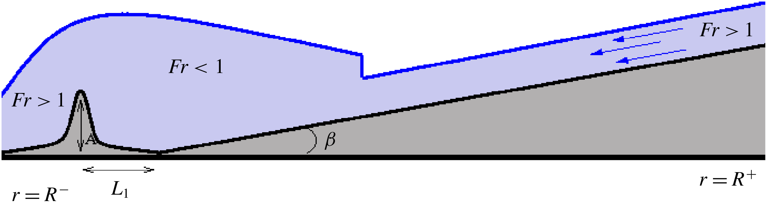
We have now to add into the model the dissipative terms and bottom topography. The bottom will consist of an inclined plane of a mild slope superposed with a bump modelling the hollow cylinder (see figure 1). Analytically, the expression of the bottom function is given by
 $$\begin{eqnarray}b(r)=\left\{\begin{array}{@{}ll@{}}\displaystyle A\frac{\left[(r-R^{-}-L_{1})^{2}-L_{1}^{2}\right]^{2}}{L_{1}^{4}}, & \text{if }0<r-R^{-}<2L_{1},\\ (r-R^{-}-2L_{1})\tan \unicode[STIX]{x1D6FD}, & \text{if }2L_{1}+R^{-}<r<R^{+}.\end{array}\right.\end{eqnarray}$$
Here
 $\unicode[STIX]{x1D6FD}$
is a small inclination angle,
 $A$
is the bump amplitude,
 $2L_{1}$
is the radial bump width,
 $R^{-}$
is the internal boundary radius and
 $R^{+}$
is the external boundary radius. The formula (5.10) is used to model the ‘physical’ cylinder of height
 $A$
which is placed at
 $r=R^{-}+L_{1}$
.
The bottom topography used in numerical simulations.

6 Initial and boundary conditions
Now, we need to impose boundary conditions on the cylinder. Formally, the number of boundary conditions should be equal to the number of characteristics entering the flow domain. For stationary flows it is natural to impose the criticality condition (Froude number is equal to one) on the top of the cylinder. When the flow is non-stationary and transcritical, the problem of boundary conditions is an open question even for the Saint-Venant equations (cf. Shiue et al. (Reference Shiue, Laminie, Temam and Tribba2011)). Indeed, at a given time we do not know whether the flow is subcritical or supercritical. In particular, if the flow is subcritical, the perturbations can propagate inside the flow domain and change the solution. We thus need a remedy to impose mathematically relevant boundary conditions. For this, we will compute the solution in a larger domain by introducing a bump allowing us to accelerate the downslope flow and transform it from subcritical to supercritical flow. Thus, the flow will be supercritical at both boundaries
 $r=R^{-}$
and
 $r=R^{+}$
. In particular, at
 $r=R^{-}$
there is no characteristic entering the flow domain, so we can use Neumann boundary conditions. At
 $r=R^{+}$
we impose all unknowns. Such an approach allowing us to control the fluid flow at the downstream crest was also used by Winters (Reference Winters2016).
We numerically solved the equations (5.7) where, additionally, the dissipative terms and bottom topography are added (see appendix A) in the computational domain:
 $$\begin{eqnarray}R^{-}\leqslant r\leqslant R^{+},\quad 0\leqslant \unicode[STIX]{x1D703}\leqslant 2\unicode[STIX]{x03C0}.\end{eqnarray}$$
The initial conditions are
 $$\begin{eqnarray}h(r,\unicode[STIX]{x1D703},t=0)=\left\{\begin{array}{@{}ll@{}}1.5h_{0}\;[\text{m}], & \text{if }r-R^{-}\leqslant 0.3(R^{+}-R^{-}),\\ h_{0}\;[\text{m}], & \text{else}\end{array}\right.\end{eqnarray}$$
 $$\begin{eqnarray}U_{r}(r,\unicode[STIX]{x1D703},t=0)=-q_{0}/(rh),\quad U_{\unicode[STIX]{x1D703}}(r,\unicode[STIX]{x1D703},t=0)=0,\end{eqnarray}$$
 $$\begin{eqnarray}P_{rr}(r,\unicode[STIX]{x1D703},t=0)=\unicode[STIX]{x1D711}h^{2},\quad P_{r\unicode[STIX]{x1D703}}(r,\unicode[STIX]{x1D703},t=0)=0,\quad P_{\unicode[STIX]{x1D703}\unicode[STIX]{x1D703}}(r,\unicode[STIX]{x1D703},t=0)=\unicode[STIX]{x1D716}\unicode[STIX]{x1D711}h^{2},\quad \unicode[STIX]{x1D716}=10^{-8}.\end{eqnarray}$$
Here
 $h_{0}$
is a flow depth at
 $r=R^{+}$
,
 $q_{0}>0$
is a flow discharge. The values of parameters are given in table 1. Obviously, we respect the inequality
 $2L_{1}<0.3(R^{+}-R^{-})$
. We have to underline that the initial conditions are unimportant, because for large time the solution is defined only by the boundary conditions.
This initial radial flow is perturbed at the boundary
 $r=R^{+}$
:
 $$\begin{eqnarray}h=h_{0},\quad U_{r}=-q_{0}(1+0.01\sin (n\unicode[STIX]{x1D703}))/(R^{+}h_{0}),\quad U_{\unicode[STIX]{x1D703}}=0,\quad P_{rr}=P_{\unicode[STIX]{x1D703}\unicode[STIX]{x1D703}}=0.5\unicode[STIX]{x1D711}h_{0}^{2},\quad P_{r\unicode[STIX]{x1D703}}=0.\end{eqnarray}$$
We added a small perturbation of the radial velocity in the
 $\unicode[STIX]{x1D703}$
-direction, with
 $n$
being any natural number. We took
 $n=16$
, which corresponds to the number of injecting pumps used, in particular, in experiments by Foglizzo et al. (Reference Foglizzo, Masset, Guilet and Durand2012). The periodic boundary condition is used in the
 $\unicode[STIX]{x1D703}$
-direction. We control that at the inner boundary
 $r=R^{-}$
in the radial direction the corresponding generalized Froude number is larger than one to guarantee the condition of supercritical flow:
 $F_{g}=U_{r}/\sqrt{gh+3P_{rr}}>1$
.
Parameters for numerical tests.

The numerical scheme is based on the splitting technique developed in Gavrilyuk et al. (Reference Gavrilyuk, Ivanova and Favrie2018a ). The first-order Godunov scheme with the HLLC Riemann solver has been used (for details, see appendix A). A mesh convergence study has been performed in order to guarantee a convergent solution. The code has been parallelized using the Message Passing Interface (MPI).
7 Numerical results
7.1 Saint-Venant equations
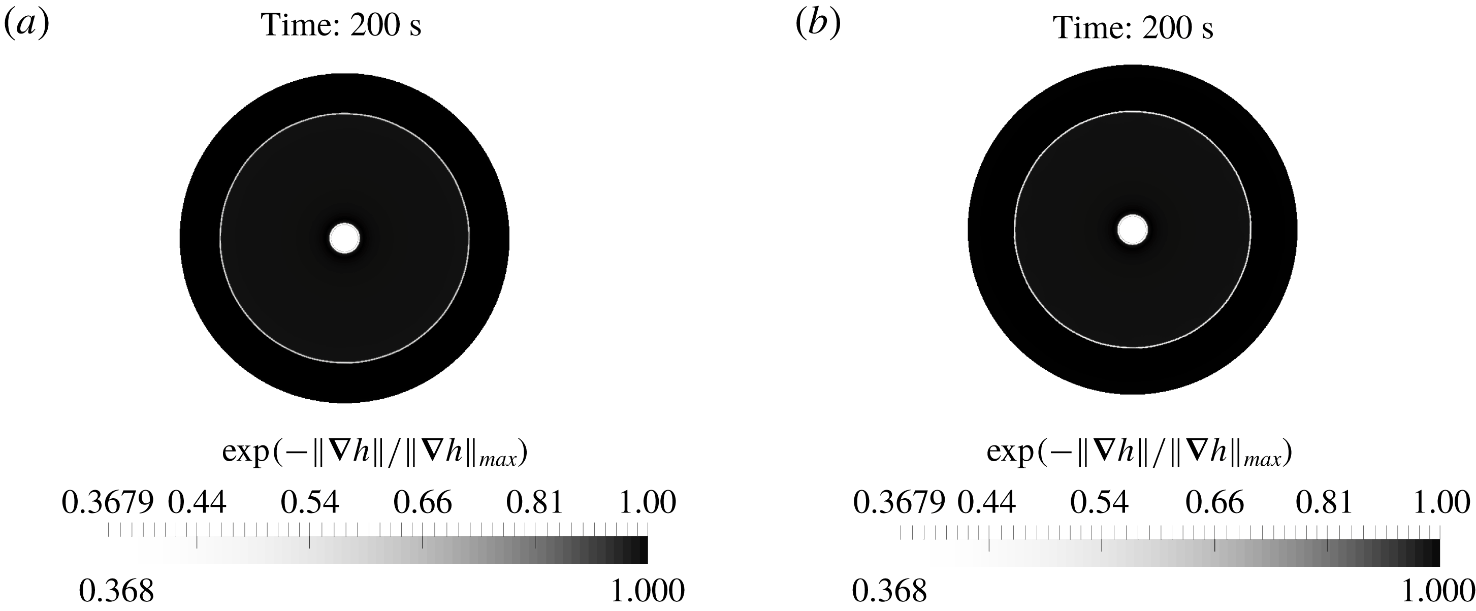
The numerical resolution of the classical shallow water equations (Saint-Venant equations) with quadratic and linear friction gives us only stationary hydraulic jumps without any oscillations or formation of rotating patterns (see figure 2). The hydraulic jump radius for the quadratic friction is a little bit larger than that corresponding to the linear friction. The same type of discharge perturbation was used as in (6.5) with the same bottom topography (5.10).
Schlieren images of the fluid depth for the Saint-Venant equations are shown (a) with quadratic friction (
 $\boldsymbol{F}=-C_{f}|\boldsymbol{U}|\boldsymbol{U},C_{f}=0.0036,\unicode[STIX]{x1D6FD}=0.05~[\text{rad}]$
), and (b) with linear friction (
 $\boldsymbol{F}=-(\unicode[STIX]{x1D708}/h)\boldsymbol{U},\unicode[STIX]{x1D6FD}=0.05~[\text{rad}]$
, with kinematic viscosity
 $\unicode[STIX]{x1D708}=10^{-6}~[\text{m}^{2}~\text{s}^{-2}]$
). The white boundaries inside the domain correspond to strong gradients of
 $h$
. The central white part corresponds to the hole. The ‘schlieren’ function was used in a standard form:
 $\exp (-\Vert \unicode[STIX]{x1D735}h\Vert /\Vert \unicode[STIX]{x1D735}h\Vert _{max})$
, where
 $\Vert \cdot \Vert$
means the Euclidean norm. The same ‘schlieren’ function was used for all computations. The first-order Godunov method with the HLLC Riemann solver was used with
 $300\times 300$
mesh cells. In both cases, the hydraulic jump was stationary. The hydraulic jump radius with the quadratic friction is a little bit larger than that with the linear friction.

In this table, ‘
 $+$
’ means that for corresponding values of
 $\unicode[STIX]{x1D711}$
and
 $C_{r}$
, the rotating cusp is formed, ‘–’ means that the cusp is absent. ‘
 $\pm$
’ means the limit behaviour.

The schlieren images of
 $h$
,
 $U_{\unicode[STIX]{x1D703}}$
and
 $\unicode[STIX]{x1D6F9}=\det (\unicode[STIX]{x1D64B})/h^{2}$
are shown. The first-order Godunov method with the HLLC Riemann solver is used with
 $500\times 500$
mesh cells,
 $C_{r}=1,\unicode[STIX]{x1D711}=2~\text{s}^{-2}$
. The central white part corresponds to the hole. The white line in the internal area corresponds to the hydraulic jump position.

7.2 Shear shallow water model with the first type of dissipation
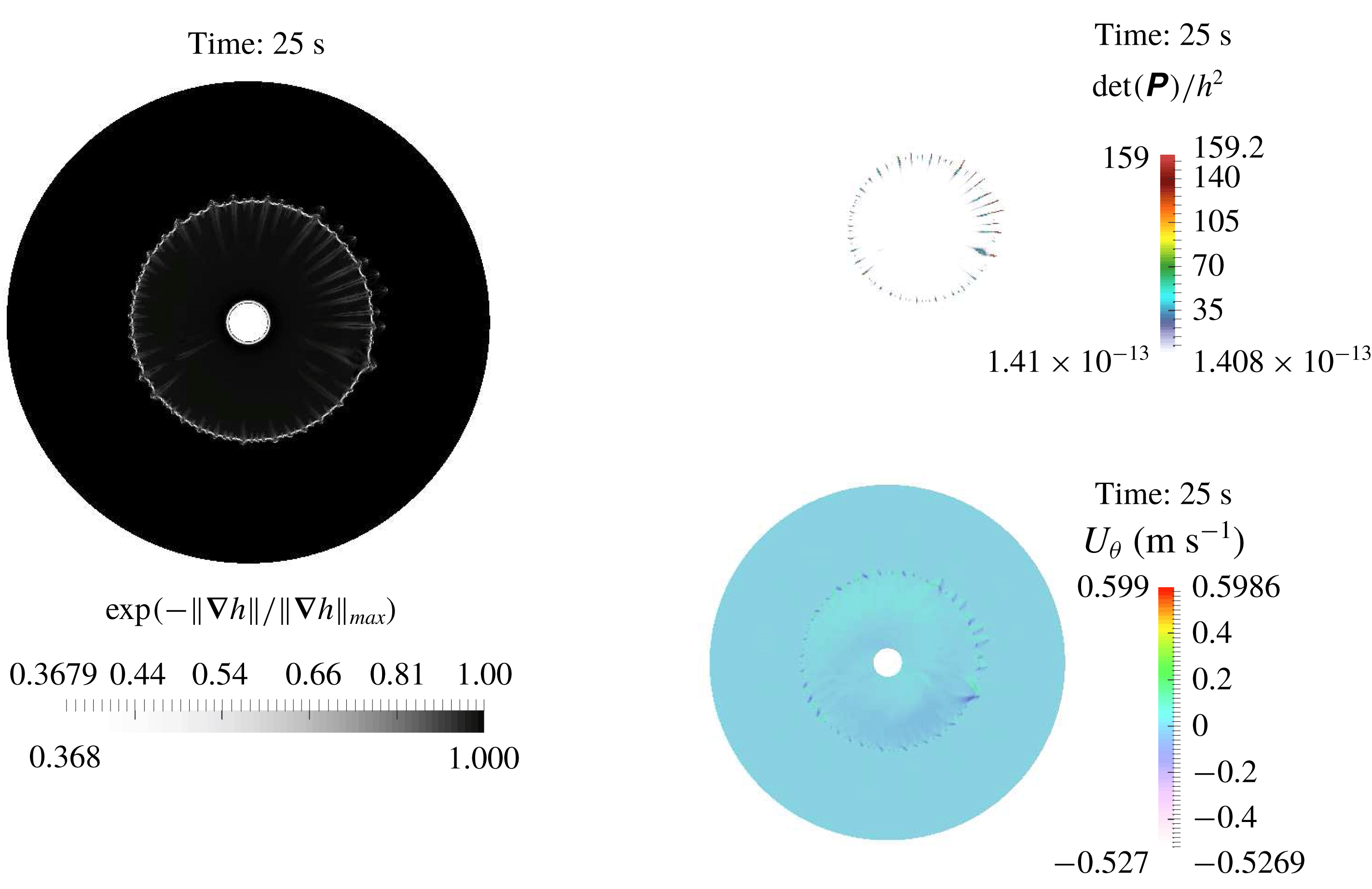
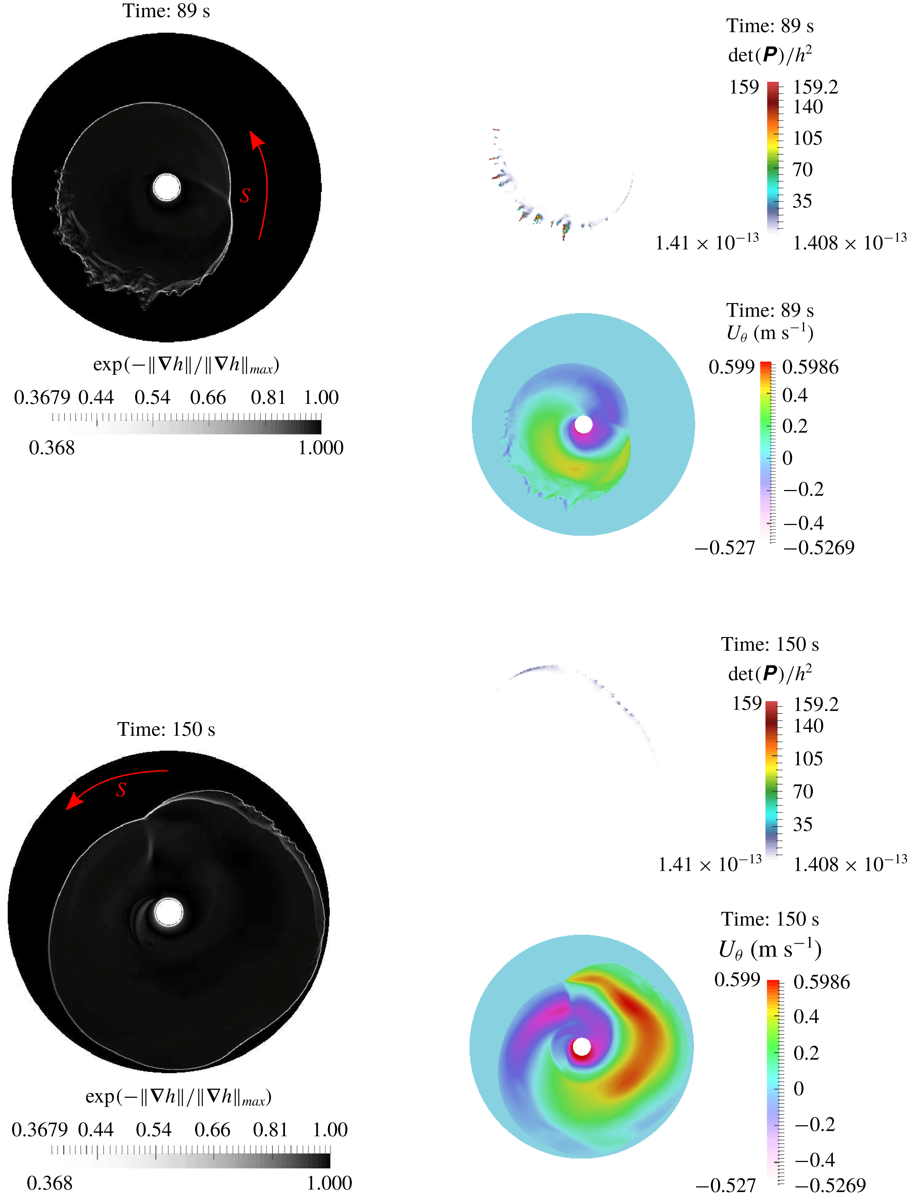
We present now the numerical results for the first type of dissipation given by (3.6). The scenario of the hydraulic jump formation in convergent radial flow consists of the following three different stages. First, almost radially symmetric hydraulic jump is formed at a time instant of approximately 25 s (see figure 3). One can see only small-amplitude non-stationary transverse perturbations on the front of the hydraulic jump. This is clearly visible in figure 3 showing, in particular, the distribution of
 $\unicode[STIX]{x1D6F9}=\det (\boldsymbol{P})/h^{2}$
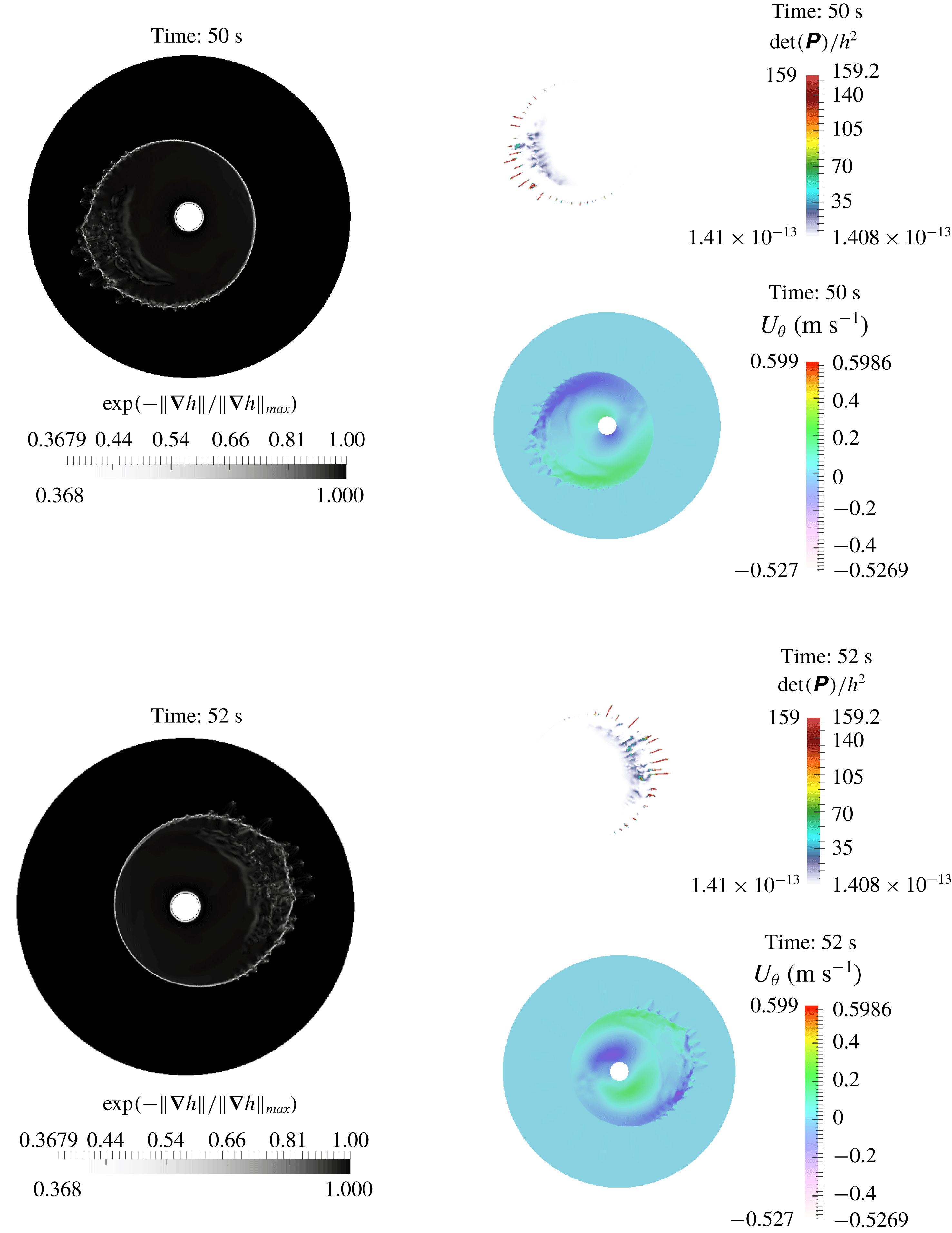
and almost vanishing tangential velocity. Then, the hydraulic jump is destabilized into a pattern exhibiting sloshing-type oscillations at a time instant of approximately 50 s. The oscillation period is approximately 4 s. In figure 4 the schlieren images are shown at time instants 50 s and 52 s (after the half-period of oscillations). Remarkably, in a certain domain of parameters, as the amplitude of the oscillations grows, a new free-surface pattern appears. More exactly, a singular point (cusp) at the free surface of the hydraulic jump appears which starts to rotate at a constant velocity. In figure 5, the cusp rotating in the positive direction is denoted by
 $S$
. As usual, we define the positive direction as a counterclockwise rotation, and negative as a clockwise rotation. The sense of rotation can easily be understood from figure 5. Indeed, ahead of the cusp the front is smooth, and behind the cusp the front is rough: transverse ‘triangular’ structures appear. The formation of ‘triangles’ behind the moving cusp was also experimentally observed (Foglizzo et al.
Reference Foglizzo, Masset, Guilet and Durand2012). The sense of rotation can be changed by a small initial perturbation. If the initial condition for the tangential velocity is taken in the form
 $U_{\unicode[STIX]{x1D703}}=\pm \unicode[STIX]{x1D707}r$
(
 $\unicode[STIX]{x1D707}$
is a small positive parameter), the sense of rotation will be determined by the sign of
 $U_{\unicode[STIX]{x1D703}}$
. The radius of the hydraulic jump increases with time. One can also see the emergence of double jump structures appearing at time instant 150 s, where the free surface changes abruptly (figure 5). The double jump structures were also observed in the case of divergent circular hydraulic jumps in Bush et al. (Reference Bush, Aristoff and Hosoi2006).
The schlieren images of
 $h$
,
 $U_{\unicode[STIX]{x1D703}}$
and
 $\unicode[STIX]{x1D6F9}=\det (\unicode[STIX]{x1D64B})/h^{2}$
are shown. The first-order Godunov method with the HLLC Riemann solver is used with
 $500\times 500$
mesh cells,
 $C_{r}=1,\unicode[STIX]{x1D711}=2~\text{s}^{-2}$
The hydraulic jump is destabilized into a pattern which corresponds to ‘sloshing’-type oscillations.

The schlieren images of
 $h$
,
 $U_{\unicode[STIX]{x1D703}}$
and
 $\unicode[STIX]{x1D6F9}=\det (\unicode[STIX]{x1D64B})/h^{2}$
are shown. The first-order Godunov method with the HLLC Riemann solver is used with
 $500\times 500$
mesh cells,
 $C_{r}=1,\unicode[STIX]{x1D711}=2~\text{s}^{-2}$
. The cusp (a singular point) denoted by
 $S$
appears at the front. It rotates in the positive direction (counterclockwise direction) shown by an arrow. Ahead of the cusp, the front is smooth, while behind the cusp the front is rough: transverse triangular structures follow the cusp.

The cusp with a rotation period of approximately
 $6$
s appears only in a certain region of parameters
 $\unicode[STIX]{x1D711}$
and
 $C_{r}$
(see table 2). The rotation period is insensitive to the variation of
 $\unicode[STIX]{x1D711}$
and
 $C_{r}$
, when they vary in the intervals
 $[2,\;20]~[\text{s}^{-2}]$
, and
 $[0.3,\;1]$
, respectively. It has been experimentally proven in Foglizzo et al. (Reference Foglizzo, Masset, Guilet and Durand2012) (see their figure 3) that the period of rotation of the cusp is proportional to the ‘hydraulic jump radius’, which is the distance between the origin and the cusp’s position. In this sense we are in a good agreement with experimental data, because the period of rotation of our cusp is 6 s for the hydraulic jump radius of approximately 35 cm.
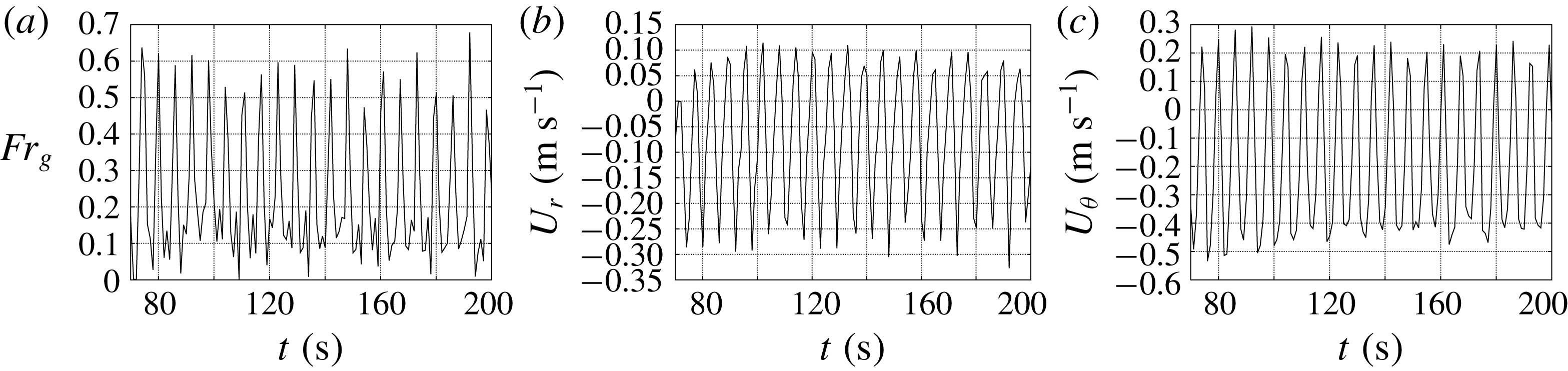
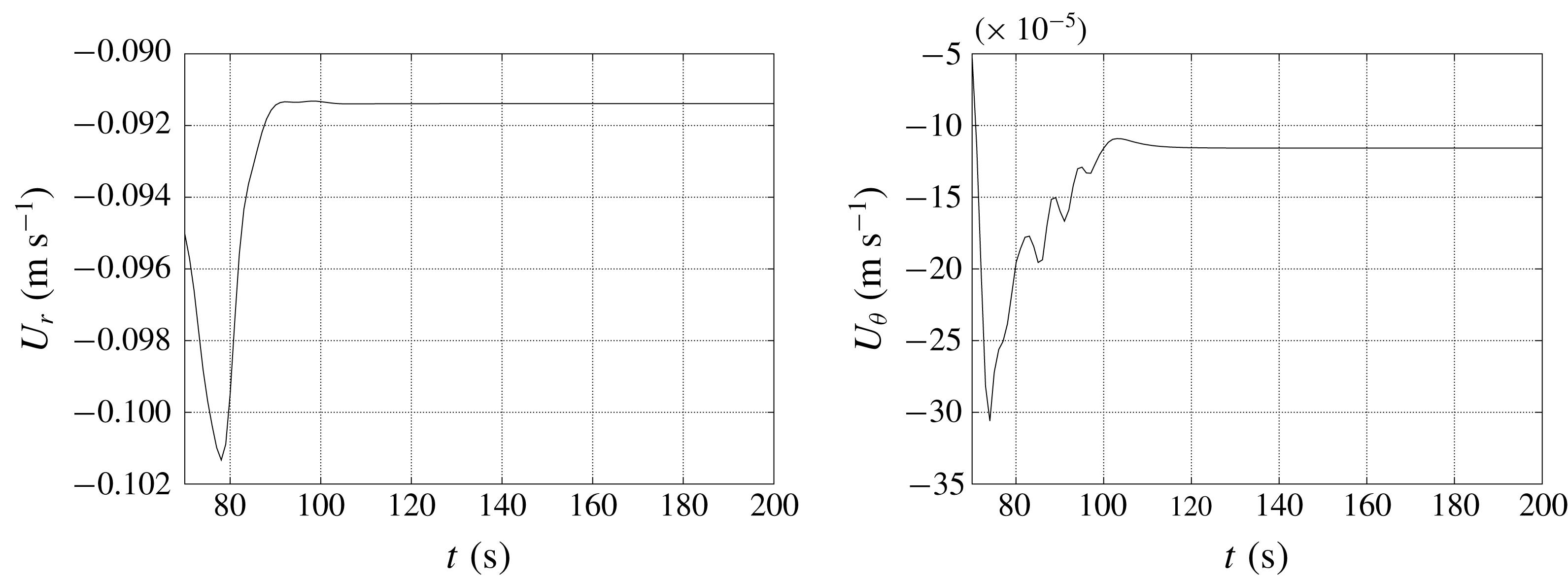
Interestingly enough, when one plots the time evolution of the velocity (both radial and tangential components) at a given point behind (but not too far) the hydraulic jump, it also shows an oscillatory behaviour with the same period of oscillations of approximately 6 s (see figure 6). Figure 6(a) proves the fact that the generalized Froude number is always smaller than one, i.e. at this point the non-stationary flow is always subcritical. Analogous plots for the computations with the Saint-Venant equations with a linear friction show negligible time variations of the flow velocity (figure 7).
In the experiments of Foglizzo et al. (Reference Foglizzo, Masset, Guilet and Durand2012) the period was approximately 3 s, but the geometry was different; as a consequence the radius of the hydraulic jump and its period of rotation were different. The main reason why we did not use the same geometry was that we could not guarantee supercritical flow at the outlet (at
 $r=R^{-}$
), which was necessary to assure the correct boundary conditions for the governing equations.
When
 $\unicode[STIX]{x1D711}$
vanishes, we do not obtain any transverse structures: the circular hydraulic jump only is formed. Recall that
 $\unicode[STIX]{x1D711}$
is associated with the enstrophy of small vortexes near the bottom Richard & Gavrilyuk (Reference Richard and Gavrilyuk2012, Reference Richard and Gavrilyuk2013).
In table 2 we studied how enstrophy
 $\unicode[STIX]{x1D711}$
and the parameter
 $C_{r}$
influence the flow behaviour. Numerical tests showed that the solution is more sensitive to the variation of
 $\unicode[STIX]{x1D711}$
than of
 $C_{r}$
. For
 $\unicode[STIX]{x1D711}$
larger than
 $10~\text{s}^{-2}$
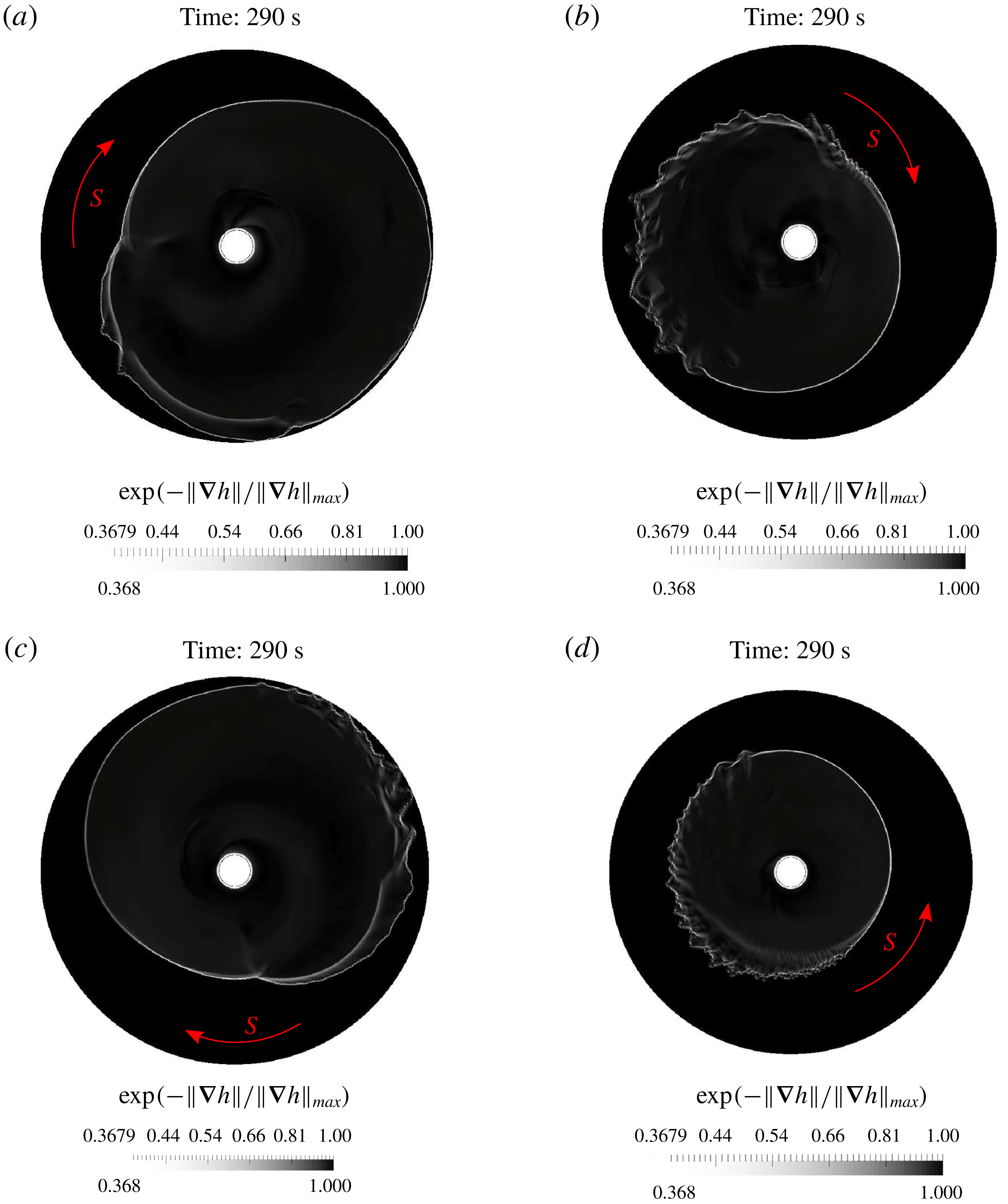
the cusp disappears, but a singular point is still visible (see figure 8).
A numerical ‘cusp’ solution was also obtained in Foglizzo et al. (Reference Foglizzo, Masset, Guilet and Durand2012) by using the Saint-Venant equations with linear friction, but for a different bottom topography. They used the criticality condition at the top of the cylinder, which corresponds to the hypothesis of the steady flow assumption.
A surprising fact also mentioned in the experiments is that the sense of rotation of the cusp and the tangential fluid velocity near the hole is opposite. This fact is also described by our model.
Our mathematical model of shear shallow water flows and the corresponding numerical method are thus capable of simulating new flow patterns appearing in radial fluid flows.
7.3 Shear shallow water model with the second type of dissipation
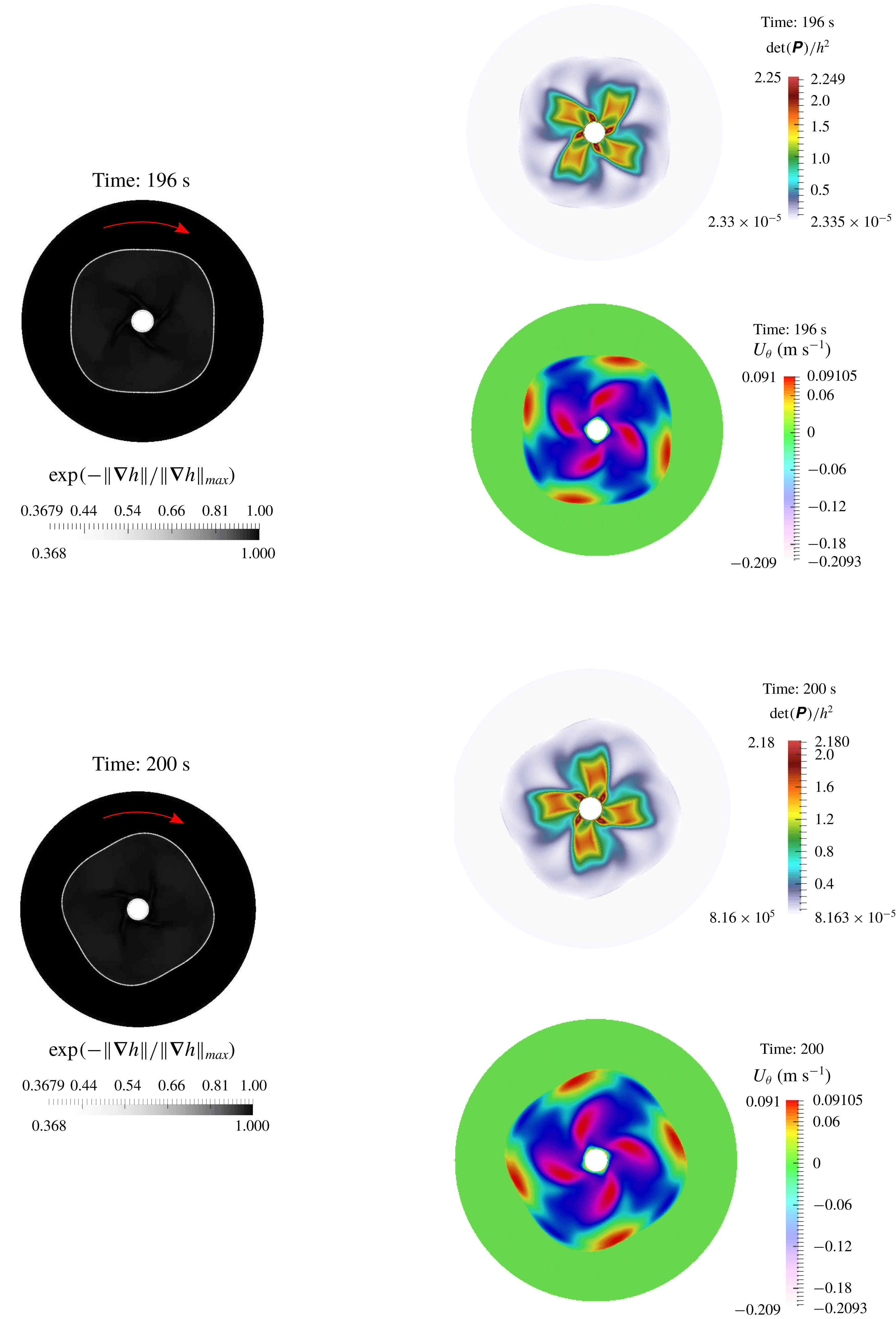
Using the second type of dissipative terms (3.10), one can see the formation of a new flow pattern: a rotating square-like hydraulic jump appears (see figure 9). The ‘corners’ of the ‘square’ are rather smooth and the shape between ‘corners’ is convex, while the corners were sharp and the shape between corners was concave in the experiments on divergent hydraulic jumps Ellegaard et al. (Reference Ellegaard, Hansen, Haaning, Hansen, Marcussen, Bohr, Hansen and Watanabe1998). This is the main difference between convergent and divergent radial flows. This type of result is not yet experimentally confirmed. Probably, as in the case of divergent hydraulic jumps, such a ‘rotating square-like structure’ can be obtained by changing the viscosity of the liquids used in the experiments.
The generalized Froude number
 $Fr_{g}=U_{r}/\sqrt{gh+3P_{rr}}$
(a) and velocity behaviour (b,c) are shown at the point
 $r=0.5(R^{+}-R^{-}),\unicode[STIX]{x1D703}=0$
as functions of time. After approximately 70 s, when the cusp is formed, this point is always in the subcritical region (behind the hydraulic jump). As previously,
 $C_{r}=1,\unicode[STIX]{x1D711}=2~\text{s}^{-2}$
. The oscillations are almost periodic with a period of approximately 6 s that corresponds to the cusp rotation period.

The radial and tangential velocity time behaviour at a given point
 $r=0.5(R^{+}-R^{-}),\unicode[STIX]{x1D703}=0$
are shown after 70 s for the classical Saint-Venant equations with linear friction. This point is always in the subcritical region. The hydraulic jump is an almost stationary one (the variation of
 $U_{\unicode[STIX]{x1D703}}$
is of the order of
 $10^{-4}~\text{m}~\text{s}^{-1}$
). The quadratic friction force gives the same results.

Schlieren images of the hydraulic jump corresponding to
 $\unicode[STIX]{x1D711}=2~\text{s}^{-2}$
(a),
 $\unicode[STIX]{x1D711}=5~\text{s}^{-2}$
(b),
 $\unicode[STIX]{x1D711}=10~\text{s}^{-2}$
(c) and
 $\unicode[STIX]{x1D711}=20~\text{s}^{-2}$
(d) are shown with
 $500\times 500$
mesh cells at the time instant 290 s. The value of
 $C_{r}$
is taken as
 $0.5$
in each case. The cusp is formed only for
 $\unicode[STIX]{x1D711}=2~\text{s}^{-2}$
and
 $\unicode[STIX]{x1D711}=5~\text{s}^{-2}$
. In the cases
 $\unicode[STIX]{x1D711}=10~\text{s}^{-2}$
and
 $\unicode[STIX]{x1D711}=20~\text{s}^{-2}$
the cusp degenerates into a moving singular point through which we have always the transition from the ‘smooth’ to the ‘rough’ region. The corresponding singular point (denoted by
 $S$
) rotates in a negative sense (clockwise direction) for all cases, excepting the case
 $\unicode[STIX]{x1D711}=20~\text{s}^{-2}$
where the sense of rotation is positive (counterclockwise direction). The sense of rotation can easily be understood, because ahead of the singular point the front is smooth, while behind the singular point the front is rough.

The second type of dissipative term is used here. The schlieren images of
 $h$
,
 $U_{\unicode[STIX]{x1D703}}$
and
 $\unicode[STIX]{x1D6F9}=\det (\unicode[STIX]{x1D64B})/h^{2}$
are shown at time instants 196 s and 200 s. The first-order Godunov method with the HLLC Riemann solver was used with
 $300\times 300$
mesh cells,
 $C_{r}=10,\unicode[STIX]{x1D711}=100~[\text{s}^{-2}]$
,
 $q=10^{-3}~[\text{m}^{3}~\text{s}^{-1}]$
. One can see the appearance of square-like structures with ‘smoothed’ edges which rotate in the clockwise direction.

8 Conclusion
Numerical modelling of multi-dimensional turbulent hydraulic jumps formed in convergent radial flow is performed and qualitatively compared to the experimental observations. Two types of ‘well posed’ dissipation laws are proposed and studied. For the first type of dissipation, in some region of parameters
 $\unicode[STIX]{x1D711}$
and
 $C_{r}$
, the formation of a rotating cusp (angular point) on the hydraulic jump front was found. For the second type of dissipation, rotating square-like hydraulic jumps were found.
The numerical validations show the capability of the model and numerical method to reproduce the multi-dimensional hydraulic jump dynamics.
Further development of this multi-dimensional model would be to add dispersive effects to describe the multi-dimensional wave propagation and breaking as was performed in the 1D case in Gavrilyuk et al. (Reference Gavrilyuk, Liapidevskii and Chesnokov2016) and Gavrilyuk, Liapidevskii & Chesnokov (Reference Gavrilyuk, Liapidevskii and Chesnokov2018b ).
Acknowledgements
The authors thank B. Nkonga, J. Massoni, S. Hank and N. Favrie for helpful discussions. We also thank the anonymous reviewers for their insightful comments and suggestions. This work was partially supported by l’Agence Nationale de la Recherche, France (grant numbers ANR-11-LABEX-0092, and ANR-11-IDEX-0001-02).
Appendix A
A.1 Governing equations in polar coordinates
We will rewrite now the system of governing equations (2.1) in polar coordinates
 $(r,\unicode[STIX]{x1D703})$
. We introduce the corresponding basis vectors:
 $$\begin{eqnarray}\boldsymbol{e}_{r}=(\cos \unicode[STIX]{x1D703},\sin \unicode[STIX]{x1D703})^{\text{T}},\quad \boldsymbol{e}_{\unicode[STIX]{x1D703}}=(-\text{sin}\unicode[STIX]{x1D703},\cos \unicode[STIX]{x1D703})^{\text{T}}.\end{eqnarray}$$
One has
 $$\begin{eqnarray}\frac{\unicode[STIX]{x2202}\boldsymbol{e}_{r}}{\unicode[STIX]{x2202}r}=0,\quad \frac{\unicode[STIX]{x2202}\boldsymbol{e}_{\unicode[STIX]{x1D703}}}{\unicode[STIX]{x2202}r}=0,\quad \frac{\unicode[STIX]{x2202}\boldsymbol{e}_{\unicode[STIX]{x1D703}}}{\unicode[STIX]{x2202}\unicode[STIX]{x1D703}}=-\boldsymbol{e}_{r},\quad \frac{\unicode[STIX]{x2202}\boldsymbol{e}_{r}}{\unicode[STIX]{x2202}\unicode[STIX]{x1D703}}=\boldsymbol{e}_{\unicode[STIX]{x1D703}}.\end{eqnarray}$$
One can then use the decomposition
 $$\begin{eqnarray}\boldsymbol{U}=U_{r}\boldsymbol{e}_{r}+U_{\unicode[STIX]{x1D703}}\boldsymbol{e}_{\unicode[STIX]{x1D703}},\quad \frac{\unicode[STIX]{x2202}\boldsymbol{U}}{\unicode[STIX]{x2202}\boldsymbol{x}}=\frac{\unicode[STIX]{x2202}\boldsymbol{U}}{\unicode[STIX]{x2202}r}\otimes \boldsymbol{e}_{r}+\frac{1}{r}\frac{\unicode[STIX]{x2202}\boldsymbol{U}}{\unicode[STIX]{x2202}\unicode[STIX]{x1D703}}\otimes \boldsymbol{e}_{\unicode[STIX]{x1D703}}.\end{eqnarray}$$
 $$\begin{eqnarray}\frac{\unicode[STIX]{x2202}\boldsymbol{U}}{\unicode[STIX]{x2202}\boldsymbol{x}}=\frac{\unicode[STIX]{x2202}U_{r}}{\unicode[STIX]{x2202}r}\boldsymbol{e}_{r}\otimes \boldsymbol{e}_{r}+\frac{\unicode[STIX]{x2202}U_{\unicode[STIX]{x1D703}}}{\unicode[STIX]{x2202}r}\boldsymbol{e}_{\unicode[STIX]{x1D703}}\otimes \boldsymbol{e}_{r}+\left(\frac{1}{r}\frac{\unicode[STIX]{x2202}U_{r}}{\unicode[STIX]{x2202}\unicode[STIX]{x1D703}}-\frac{U_{\unicode[STIX]{x1D703}}}{r}\right)\boldsymbol{e}_{r}\otimes \boldsymbol{e}_{\unicode[STIX]{x1D703}}+\frac{1}{r}\left(U_{r}+\frac{\unicode[STIX]{x2202}U_{\unicode[STIX]{x1D703}}}{\unicode[STIX]{x2202}\unicode[STIX]{x1D703}}\right)\boldsymbol{e}_{\unicode[STIX]{x1D703}}\otimes \boldsymbol{e}_{\unicode[STIX]{x1D703}}.\end{eqnarray}$$
Equation (A 4) implies
 $$\begin{eqnarray}\text{div}\,\boldsymbol{U}=\frac{1}{r}\frac{\unicode[STIX]{x2202}U_{\unicode[STIX]{x1D703}}}{\unicode[STIX]{x2202}\unicode[STIX]{x1D703}}+\frac{1}{r}\frac{\unicode[STIX]{x2202}}{\unicode[STIX]{x2202}r}\left(rU_{r}\right).\end{eqnarray}$$
Also, one has
 $$\begin{eqnarray}\unicode[STIX]{x1D64B}=P_{rr}\boldsymbol{e}_{r}\otimes \boldsymbol{e}_{r}+P_{r\unicode[STIX]{x1D703}}\boldsymbol{e}_{r}\otimes \boldsymbol{e}_{\unicode[STIX]{x1D703}}+P_{\unicode[STIX]{x1D703}r}\boldsymbol{e}_{\unicode[STIX]{x1D703}}\otimes \boldsymbol{e}_{r}+P_{\unicode[STIX]{x1D703}\unicode[STIX]{x1D703}}\boldsymbol{e}_{\unicode[STIX]{x1D703}}\otimes \boldsymbol{e}_{\unicode[STIX]{x1D703}},\quad P_{r\unicode[STIX]{x1D703}}=P_{\unicode[STIX]{x1D703}r}.\end{eqnarray}$$
Then,
 $$\begin{eqnarray}\text{div}(h\unicode[STIX]{x1D64B})=(\text{div}(\unicode[STIX]{x1D64B}))h+\unicode[STIX]{x1D64B}\unicode[STIX]{x1D735}h,\end{eqnarray}$$
where
 $$\begin{eqnarray}\text{div}(\unicode[STIX]{x1D64B})=\left(\frac{\unicode[STIX]{x2202}P_{rr}}{\unicode[STIX]{x2202}r}+\frac{1}{r}\frac{\unicode[STIX]{x2202}P_{r\unicode[STIX]{x1D703}}}{\unicode[STIX]{x2202}\unicode[STIX]{x1D703}}+\frac{1}{r}(P_{rr}-P_{\unicode[STIX]{x1D703}\unicode[STIX]{x1D703}}),\frac{\unicode[STIX]{x2202}P_{r\unicode[STIX]{x1D703}}}{\unicode[STIX]{x2202}r}+\frac{1}{r}\frac{\unicode[STIX]{x2202}P_{\unicode[STIX]{x1D703}\unicode[STIX]{x1D703}}}{\unicode[STIX]{x2202}\unicode[STIX]{x1D703}}+\frac{2}{r}P_{r\unicode[STIX]{x1D703}}\right).\end{eqnarray}$$
Also, the material derivative defined by (2.2) is transformed to
 $$\begin{eqnarray}\frac{\text{D}}{\text{D}t}=\frac{\unicode[STIX]{x2202}}{\unicode[STIX]{x2202}t}+U_{r}\frac{\unicode[STIX]{x2202}}{\unicode[STIX]{x2202}r}+\frac{U_{\unicode[STIX]{x1D703}}}{r}\frac{\unicode[STIX]{x2202}}{\unicode[STIX]{x2202}\unicode[STIX]{x1D703}}.\end{eqnarray}$$
Using (A 2), one obtains
 $$\begin{eqnarray}\frac{\unicode[STIX]{x2202}\unicode[STIX]{x1D64B}}{\unicode[STIX]{x2202}r}=\left(\begin{array}{@{}cc@{}}{\displaystyle \frac{\unicode[STIX]{x2202}P_{rr}}{\unicode[STIX]{x2202}r}} & {\displaystyle \frac{\unicode[STIX]{x2202}P_{r\unicode[STIX]{x1D703}}}{\unicode[STIX]{x2202}r}}\\ {\displaystyle \frac{\unicode[STIX]{x2202}P_{r\unicode[STIX]{x1D703}}}{\unicode[STIX]{x2202}r}} & {\displaystyle \frac{\unicode[STIX]{x2202}P_{\unicode[STIX]{x1D703}\unicode[STIX]{x1D703}}}{\unicode[STIX]{x2202}r}}\end{array}\right),\quad {\displaystyle \frac{\unicode[STIX]{x2202}\unicode[STIX]{x1D64B}}{\unicode[STIX]{x2202}\unicode[STIX]{x1D703}}}=\left(\begin{array}{@{}cc@{}}{\displaystyle \frac{\unicode[STIX]{x2202}P_{rr}}{\unicode[STIX]{x2202}\unicode[STIX]{x1D703}}}-2P_{r\unicode[STIX]{x1D703}} & {\displaystyle \frac{\unicode[STIX]{x2202}P_{r\unicode[STIX]{x1D703}}}{\unicode[STIX]{x2202}\unicode[STIX]{x1D703}}}+P_{rr}-P_{\unicode[STIX]{x1D703}\unicode[STIX]{x1D703}}\\ {\displaystyle \frac{\unicode[STIX]{x2202}P_{r\unicode[STIX]{x1D703}}}{\unicode[STIX]{x2202}\unicode[STIX]{x1D703}}}+P_{rr}-P_{\unicode[STIX]{x1D703}\unicode[STIX]{x1D703}} & {\displaystyle \frac{\unicode[STIX]{x2202}P_{\unicode[STIX]{x1D703}\unicode[STIX]{x1D703}}}{\unicode[STIX]{x2202}\unicode[STIX]{x1D703}}}+2P_{r\unicode[STIX]{x1D703}}\end{array}\right).\end{eqnarray}$$
One can finally obtain the system (2.1) in polar coordinates:
 $$\begin{eqnarray}\displaystyle & \displaystyle \frac{\unicode[STIX]{x2202}(hr)}{\unicode[STIX]{x2202}t}+\frac{\unicode[STIX]{x2202}(rhU_{r})}{\unicode[STIX]{x2202}r}+\frac{\unicode[STIX]{x2202}(hU_{\unicode[STIX]{x1D703}})}{\unicode[STIX]{x2202}\unicode[STIX]{x1D703}}=0, & \displaystyle\end{eqnarray}$$
 $$\begin{eqnarray}\displaystyle & \displaystyle \frac{\unicode[STIX]{x2202}(rhU_{r})}{\unicode[STIX]{x2202}t}+\frac{\unicode[STIX]{x2202}}{\unicode[STIX]{x2202}r}\left\{r\left(hU_{r}^{2}+\frac{gh^{2}}{2}+hP_{rr}\right)\right\}+\frac{\unicode[STIX]{x2202}}{\unicode[STIX]{x2202}\unicode[STIX]{x1D703}}(hU_{r}U_{\unicode[STIX]{x1D703}}+hP_{r\unicode[STIX]{x1D703}}) & \displaystyle \nonumber\\ \displaystyle & \displaystyle =h(U_{\unicode[STIX]{x1D703}}^{2}+P_{\unicode[STIX]{x1D703}\unicode[STIX]{x1D703}})+\frac{gh^{2}}{2},\hphantom{\frac{\unicode[STIX]{x2202}}{\unicode[STIX]{x2202}\unicode[STIX]{x1D703}}\frac{\unicode[STIX]{x2202}}{\unicode[STIX]{x2202}\unicode[STIX]{x1D703}}(hU_{r}U_{\unicode[STIX]{x1D703}}+hP_{r\unicode[STIX]{x1D703}})} & \displaystyle\end{eqnarray}$$
 $$\begin{eqnarray}\displaystyle & \displaystyle \frac{\unicode[STIX]{x2202}\left(rhU_{\unicode[STIX]{x1D703}}\right)}{\unicode[STIX]{x2202}t}+\frac{\unicode[STIX]{x2202}}{\unicode[STIX]{x2202}r}\left\{rh\left(U_{r}U_{\unicode[STIX]{x1D703}}+P_{r\unicode[STIX]{x1D703}}\right)\right\}+\frac{\unicode[STIX]{x2202}}{\unicode[STIX]{x2202}\unicode[STIX]{x1D703}}\left(hU_{\unicode[STIX]{x1D703}}^{2}+\frac{gh^{2}}{2}+hP_{\unicode[STIX]{x1D703}\unicode[STIX]{x1D703}}\right) & \displaystyle \nonumber\\ \displaystyle & \displaystyle =-h\left(U_{r}U_{\unicode[STIX]{x1D703}}+P_{r\unicode[STIX]{x1D703}}\right),\hphantom{\frac{\unicode[STIX]{x2202}}{\unicode[STIX]{x2202}\unicode[STIX]{x1D703}}\left(hU_{\unicode[STIX]{x1D703}}^{2}+\frac{gh^{2}}{2}+hP_{\unicode[STIX]{x1D703}\unicode[STIX]{x1D703}}\right)} & \displaystyle\end{eqnarray}$$
 $$\begin{eqnarray}\displaystyle & \displaystyle \frac{\text{D}P_{rr}}{\text{D}t}-4\frac{U_{\unicode[STIX]{x1D703}}}{r}P_{r\unicode[STIX]{x1D703}}+2\left(\frac{\unicode[STIX]{x2202}U_{r}}{\unicode[STIX]{x2202}r}P_{rr}+\frac{P_{r\unicode[STIX]{x1D703}}}{r}\frac{\unicode[STIX]{x2202}U_{r}}{\unicode[STIX]{x2202}\unicode[STIX]{x1D703}}\right)=0, & \displaystyle\end{eqnarray}$$
 $$\begin{eqnarray}\displaystyle & \displaystyle \frac{\text{D}P_{r\unicode[STIX]{x1D703}}}{\text{D}t}+\frac{U_{\unicode[STIX]{x1D703}}}{r}\left(P_{rr}-2P_{\unicode[STIX]{x1D703}\unicode[STIX]{x1D703}}\right)+\frac{P_{\unicode[STIX]{x1D703}\unicode[STIX]{x1D703}}}{r}\frac{\unicode[STIX]{x2202}U_{r}}{\unicode[STIX]{x2202}\unicode[STIX]{x1D703}}+P_{rr}\frac{\unicode[STIX]{x2202}U_{\unicode[STIX]{x1D703}}}{\unicode[STIX]{x2202}r}+\frac{P_{r\unicode[STIX]{x1D703}}}{r}\left\{\frac{\unicode[STIX]{x2202}U_{\unicode[STIX]{x1D703}}}{\unicode[STIX]{x2202}\unicode[STIX]{x1D703}}+\frac{\unicode[STIX]{x2202}(rU_{r})}{\unicode[STIX]{x2202}r}\right\}=0, & \displaystyle \nonumber\\ \displaystyle & & \displaystyle\end{eqnarray}$$
 $$\begin{eqnarray}\displaystyle & \displaystyle \frac{\text{D}P_{\unicode[STIX]{x1D703}\unicode[STIX]{x1D703}}}{\text{D}t}+2\frac{U_{\unicode[STIX]{x1D703}}}{r}P_{r\unicode[STIX]{x1D703}}+2\left\{\frac{\unicode[STIX]{x2202}U_{\unicode[STIX]{x1D703}}}{\unicode[STIX]{x2202}r}P_{r\unicode[STIX]{x1D703}}+\frac{P_{\unicode[STIX]{x1D703}\unicode[STIX]{x1D703}}}{r}\left(\frac{\unicode[STIX]{x2202}U_{\unicode[STIX]{x1D703}}}{\unicode[STIX]{x2202}\unicode[STIX]{x1D703}}+U_{r}\right)\right\}=0, & \displaystyle\end{eqnarray}$$
 $$\begin{eqnarray}\displaystyle & \displaystyle \frac{\unicode[STIX]{x2202}}{\unicode[STIX]{x2202}t}\left\{hr\left(\frac{1}{2}|\boldsymbol{U}|^{2}+E\right)\right\}+\frac{\unicode[STIX]{x2202}}{\unicode[STIX]{x2202}r}\left\{r\left[hU_{r}\left(\frac{1}{2}|\boldsymbol{U}|^{2}+E\right)+\frac{gh^{2}}{2}U_{r}+h(P_{rr}U_{r}+P_{r\unicode[STIX]{x1D703}}U_{\unicode[STIX]{x1D703}})\right]\right\} & \displaystyle \nonumber\\ \displaystyle & \displaystyle +\,\frac{\unicode[STIX]{x2202}}{\unicode[STIX]{x2202}\unicode[STIX]{x1D703}}\left\{hU_{\unicode[STIX]{x1D703}}\left(\frac{1}{2}|\boldsymbol{U}|^{2}+E\right)+\frac{gh^{2}}{2}U_{\unicode[STIX]{x1D703}}+h(P_{r\unicode[STIX]{x1D703}}U_{r}+P_{\unicode[STIX]{x1D703}\unicode[STIX]{x1D703}}U_{\unicode[STIX]{x1D703}})\right\}=0.\hphantom{\frac{\unicode[STIX]{x2202}hr\unicode[STIX]{x1D703}}{\unicode[STIX]{x2202}t}} & \displaystyle\end{eqnarray}$$
A.2 Numerical splitting technique in polar coordinates
The method follows the splitting technique proposed in Gavrilyuk et al. (Reference Gavrilyuk, Ivanova and Favrie2018a
) in Cartesian coordinates. We adapt this approach to polar coordinates. For this, we solve first the model in the
 $r$
-direction, then in the
 $\unicode[STIX]{x1D703}$
-direction. For each direction, the two subsystems, proposed below, are solved separately. Each subsystem is hyperbolic and admits the energy conservation law.
A.2.1 Subsystem 1 in the
 $r$
-direction

The first subsystem in the
 $r$
-direction is
 $$\begin{eqnarray}\displaystyle & \displaystyle \frac{\unicode[STIX]{x2202}(rh)}{\unicode[STIX]{x2202}t}+\frac{\unicode[STIX]{x2202}(rhU_{r})}{\unicode[STIX]{x2202}r}=0, & \displaystyle\end{eqnarray}$$
 $$\begin{eqnarray}\displaystyle & \displaystyle \frac{\unicode[STIX]{x2202}(rhU_{r})}{\unicode[STIX]{x2202}t}+\frac{\unicode[STIX]{x2202}}{\unicode[STIX]{x2202}r}\left(r\left(hU_{r}^{2}+\frac{gh^{2}}{2}+hP_{rr}\right)\right)=h(U_{\unicode[STIX]{x1D703}}^{2}+P_{\unicode[STIX]{x1D703}\unicode[STIX]{x1D703}})+\frac{gh^{2}}{2}, & \displaystyle\end{eqnarray}$$
 $$\begin{eqnarray}\displaystyle & \displaystyle \frac{\unicode[STIX]{x2202}\left(rhU_{\unicode[STIX]{x1D703}}\right)}{\unicode[STIX]{x2202}t}+\frac{\unicode[STIX]{x2202}}{\unicode[STIX]{x2202}r}\left(rhU_{r}U_{\unicode[STIX]{x1D703}}\right)=-h\left(U_{r}U_{\unicode[STIX]{x1D703}}+P_{r\unicode[STIX]{x1D703}}\right), & \displaystyle\end{eqnarray}$$
 $$\begin{eqnarray}\displaystyle & \displaystyle \frac{\unicode[STIX]{x2202}(rhP_{rr})}{\unicode[STIX]{x2202}t}+\frac{\unicode[STIX]{x2202}(rhU_{r}P_{rr})}{\unicode[STIX]{x2202}r}+2rhP_{rr}\frac{\unicode[STIX]{x2202}U_{r}}{\unicode[STIX]{x2202}r}=4hP_{r\unicode[STIX]{x1D703}}U_{\unicode[STIX]{x1D703}}, & \displaystyle\end{eqnarray}$$
 $$\begin{eqnarray}\displaystyle & \displaystyle \frac{\unicode[STIX]{x2202}(rP_{r\unicode[STIX]{x1D703}})}{\unicode[STIX]{x2202}t}+\frac{\unicode[STIX]{x2202}(rU_{r}P_{r\unicode[STIX]{x1D703}})}{\unicode[STIX]{x2202}r}=U_{\unicode[STIX]{x1D703}}\left(2P_{\unicode[STIX]{x1D703}\unicode[STIX]{x1D703}}-P_{rr}\right), & \displaystyle\end{eqnarray}$$
 $$\begin{eqnarray}\displaystyle & \displaystyle \frac{\unicode[STIX]{x2202}(hrP_{\unicode[STIX]{x1D703}\unicode[STIX]{x1D703}})}{\unicode[STIX]{x2202}t}+\frac{\unicode[STIX]{x2202}(rhU_{r}P_{\unicode[STIX]{x1D703}\unicode[STIX]{x1D703}})}{\unicode[STIX]{x2202}r}=-2h(P_{r\unicode[STIX]{x1D703}}U_{\unicode[STIX]{x1D703}}+P_{\unicode[STIX]{x1D703}\unicode[STIX]{x1D703}}U_{r}),\qquad & \displaystyle\end{eqnarray}$$
The subsystem (A 12) admits the energy conservation law
 $$\begin{eqnarray}\frac{\unicode[STIX]{x2202}}{\unicode[STIX]{x2202}t}\left\{rh\left(\frac{1}{2}|\boldsymbol{U}|^{2}+E\right)\right\}+\frac{\unicode[STIX]{x2202}}{\unicode[STIX]{x2202}r}\left\{r\left[hU_{r}\left(\frac{1}{2}|\boldsymbol{U}|^{2}+E\right)+\frac{gh^{2}}{2}U_{r}+hP_{rr}U_{r}\right]\right\}=0,\end{eqnarray}$$
where
 $E=(gh+P_{rr}+P_{\unicode[STIX]{x1D703}\unicode[STIX]{x1D703}})/2$
.
The system is hyperbolic with the eigenvalues given by
 $$\begin{eqnarray}\unicode[STIX]{x1D706}_{1,2,3,4}=U_{r},\quad \unicode[STIX]{x1D706}_{5,6}=U_{r}\pm \sqrt{gh+3P_{rr}}.\end{eqnarray}$$
The equation (A 12d
) is not conservative. The jump relation for this equation is not well defined. The value of
 $P_{rr}$
will be corrected using the energy equation (A 13). Numerically, we solve first the system (A 12) where the equation (A 12d
) is replaced by
 $$\begin{eqnarray}{\displaystyle \frac{\unicode[STIX]{x2202}(rhP_{rr})}{\unicode[STIX]{x2202}t}}+{\displaystyle \frac{\unicode[STIX]{x2202}(rhU_{r}P_{rr})}{\unicode[STIX]{x2202}r}}=0.\end{eqnarray}$$
We update then
 $rhP_{rr}$
by using (A 13).
Godunov-type method and correction of the non-conservative term
 $rhP_{rr}$
Subsystem 1 can be rewritten in the following form:
 $$\begin{eqnarray}\frac{\unicode[STIX]{x2202}\boldsymbol{W}}{\unicode[STIX]{x2202}t}+\frac{\unicode[STIX]{x2202}(r\boldsymbol{F})}{\unicode[STIX]{x2202}r}=\boldsymbol{S}^{r},\end{eqnarray}$$
where the vector of ‘conservative’ variables
 $\boldsymbol{W}$
, the vector of fluxes
 $\boldsymbol{F}(\boldsymbol{W})$
and the geometric source term vector
 $\boldsymbol{S}^{r}(\boldsymbol{W})$
are
 $$\begin{eqnarray}\displaystyle & \displaystyle \boldsymbol{W}=(rh,rhU_{r},rhU_{\unicode[STIX]{x1D703}},rhP_{rr},rP_{r\unicode[STIX]{x1D703}},rhP_{\unicode[STIX]{x1D703}\unicode[STIX]{x1D703}},rh(E+{\textstyle \frac{1}{2}}|\boldsymbol{U}|^{2}))^{\text{T}}, & \displaystyle\end{eqnarray}$$
 $$\begin{eqnarray}\displaystyle & \displaystyle \boldsymbol{F}(\boldsymbol{W})=(hU_{r},hU_{r}^{2}+p,hU_{r}U_{\unicode[STIX]{x1D703}},hU_{r}P_{rr},U_{r}P_{r\unicode[STIX]{x1D703}},hU_{r}P_{\unicode[STIX]{x1D703}\unicode[STIX]{x1D703}},hU_{r}({\textstyle \frac{1}{2}}|\boldsymbol{U}|+E)+pU_{r})^{\text{T}}, & \displaystyle \nonumber\\ \displaystyle & & \displaystyle\end{eqnarray}$$
 $$\begin{eqnarray}\displaystyle \boldsymbol{S}^{r} & = & \displaystyle \left(0,h\left(U_{\unicode[STIX]{x1D703}}^{2}+P_{\unicode[STIX]{x1D703}\unicode[STIX]{x1D703}}\right)+\frac{gh^{2}}{2},-h\left(U_{r}U_{\unicode[STIX]{x1D703}}+P_{r\unicode[STIX]{x1D703}}\right),\right.\nonumber\\ \displaystyle & & \displaystyle \quad \left.4hP_{r\unicode[STIX]{x1D703}}U_{\unicode[STIX]{x1D703}},U_{\unicode[STIX]{x1D703}}\left(2P_{\unicode[STIX]{x1D703}\unicode[STIX]{x1D703}}-P_{rr}\right)-P_{r\unicode[STIX]{x1D703}}U_{r},-2h\left(P_{r\unicode[STIX]{x1D703}}U_{\unicode[STIX]{x1D703}}+P_{\unicode[STIX]{x1D703}\unicode[STIX]{x1D703}}U_{r}\right),0\vphantom{\frac{gh^{2}}{2}}\right)^{\text{T}},\quad\end{eqnarray}$$
with
 $$\begin{eqnarray}p=gh^{2}/2+hP_{rr},\quad E=(gh+P_{rr}+P_{\unicode[STIX]{x1D703}\unicode[STIX]{x1D703}})/2.\end{eqnarray}$$
Let us consider now a fixed grid of size
 $\unicode[STIX]{x0394}r=r_{i+1/2}-r_{i-1/2}$
, the time increment is defined as
 $\unicode[STIX]{x0394}t=t^{n+1}-t^{n}$
which must respect the Courant–Friedrichs–Lewy (CFL) condition. The discrete values of the vector function
 $\boldsymbol{W}$
at
 $(r_{i},t^{n})$
will be denoted by
 $\boldsymbol{W}_{i}^{n}$
. Integrating the conservation laws (A 16) on
 $[r_{i-1/2},r_{i+1/2}]\times [t^{n},t^{n+1}]$
, one obtains the conservative finite volume Godunov scheme on a fixed grid:
 $$\begin{eqnarray}\boldsymbol{W}_{i}^{n+1}=\boldsymbol{W}_{i}^{n}-\frac{\unicode[STIX]{x0394}t}{\unicode[STIX]{x0394}r}(r_{i+1/2}(\boldsymbol{F}_{i+1/2}^{\ast ,n}-\boldsymbol{S}_{i}^{r,n})-r_{i-1/2}(\boldsymbol{F}_{i-1/2}^{\ast ,n}-\boldsymbol{S}_{i}^{r,n})),\end{eqnarray}$$
where
 $\boldsymbol{F}_{i+1/2}^{\ast ,n}$
and
 $\boldsymbol{F}_{i-1/2}^{\ast ,n}$
are the numerical fluxes. They are constant across interfaces between cells during the time step. For computing the fluxes
 $\boldsymbol{F}_{i+1/2}^{\ast ,n}=\boldsymbol{F}_{i+1/2}^{\ast ,n}(\boldsymbol{W}_{i}^{n},\boldsymbol{W}_{i+1}^{n})$
and
 $\boldsymbol{F}_{i-1/2}^{\ast ,n}=\boldsymbol{F}_{i-1/2}^{\ast ,n}(\boldsymbol{W}_{i-1}^{n},\boldsymbol{W}_{i}^{n})$
, we use approximate solution of the Riemann problem between cells
 $i,i+1$
and
 $i-1,i$
, respectively.
Using the energy conservative law, the non-conservative term
 $rhP_{rr}$
is updated in the following way:
 $$\begin{eqnarray}(rhP_{rr})=2(rhE)-\frac{g(rh)^{2}}{r}-(rhP_{\unicode[STIX]{x1D703}\unicode[STIX]{x1D703}}).\end{eqnarray}$$
The ‘mathematical’ entropy
 $\unicode[STIX]{x1D6F9}$
corresponding to the vorticity formation is increasing through the shock at this step (for proof see Gavrilyuk et al. (Reference Gavrilyuk, Ivanova and Favrie2018a
)).
A.2.2 Subsystem 2 in the
$r$
-direction

The subsystem 2 in the
 $r$
-direction is
 $$\begin{eqnarray}\displaystyle & \displaystyle \frac{\unicode[STIX]{x2202}(rh)}{\unicode[STIX]{x2202}t}=0, & \displaystyle\end{eqnarray}$$
 $$\begin{eqnarray}\displaystyle & \displaystyle \frac{\unicode[STIX]{x2202}(rhU_{r})}{\unicode[STIX]{x2202}t}=0, & \displaystyle\end{eqnarray}$$
 $$\begin{eqnarray}\displaystyle & \displaystyle \frac{\unicode[STIX]{x2202}\left(rhU_{\unicode[STIX]{x1D703}}\right)}{\unicode[STIX]{x2202}t}+\frac{\unicode[STIX]{x2202}}{\unicode[STIX]{x2202}r}\left(rhP_{r\unicode[STIX]{x1D703}}\right)=0, & \displaystyle\end{eqnarray}$$
 $$\begin{eqnarray}\displaystyle & \displaystyle \frac{\unicode[STIX]{x2202}\left(rhP_{rr}\right)}{\unicode[STIX]{x2202}t}=0, & \displaystyle\end{eqnarray}$$
 $$\begin{eqnarray}\displaystyle & \displaystyle \frac{\unicode[STIX]{x2202}\left(rP_{r\unicode[STIX]{x1D703}}\right)}{\unicode[STIX]{x2202}t}+rP_{rr}\frac{\unicode[STIX]{x2202}U_{\unicode[STIX]{x1D703}}}{\unicode[STIX]{x2202}r}=0, & \displaystyle\end{eqnarray}$$
 $$\begin{eqnarray}\displaystyle & \displaystyle \frac{\unicode[STIX]{x2202}\left(rhP_{\unicode[STIX]{x1D703}\unicode[STIX]{x1D703}}\right)}{\unicode[STIX]{x2202}t}+2rhP_{r\unicode[STIX]{x1D703}}\frac{\unicode[STIX]{x2202}U_{\unicode[STIX]{x1D703}}}{\unicode[STIX]{x2202}r}=0. & \displaystyle\end{eqnarray}$$
 $$\begin{eqnarray}\frac{\unicode[STIX]{x2202}}{\unicode[STIX]{x2202}t}\left\{rh\left(\frac{|\boldsymbol{U}|^{2}}{2}+E\right)\right\}+\frac{\unicode[STIX]{x2202}}{\unicode[STIX]{x2202}r}\left(rhU_{\unicode[STIX]{x1D703}}P_{r\unicode[STIX]{x1D703}}\right)=0.\end{eqnarray}$$
The system is hyperbolic with the eigenvalues given by
 $$\begin{eqnarray}\unicode[STIX]{x1D706}_{1,2,3,4}=0,\quad \unicode[STIX]{x1D706}_{5,6}=\pm \sqrt{P_{rr}}.\end{eqnarray}$$
Again, system (A 23)–(A 24) is overdetermined. One can note that there are two non-conservative equations. The product
 $(rP_{rr}(\unicode[STIX]{x2202}U_{\unicode[STIX]{x1D703}}/\unicode[STIX]{x2202}r))$
in (A 23e
) is well defined. It is not the case for the term
 $(2rhP_{r\unicode[STIX]{x1D703}}(\unicode[STIX]{x2202}U_{\unicode[STIX]{x1D703}}/\unicode[STIX]{x2202}r))$
in (A 23f
). In the following, this equation will be replaced by
 $\unicode[STIX]{x2202}(rhP_{\unicode[STIX]{x1D703}\unicode[STIX]{x1D703}})/\unicode[STIX]{x2202}t=0$
at the first step, and then the energy conservation law will be used to update the value of
 $P_{\unicode[STIX]{x1D703}\unicode[STIX]{x1D703}}$
.
In particular, the estimation of
 $P_{r\unicode[STIX]{x1D703}}$
at time instant
 $(t+\unicode[STIX]{x0394}t)$
is given by
 $$\begin{eqnarray}\left(rP_{r\unicode[STIX]{x1D703}}\right)(r,t+\unicode[STIX]{x0394}t)=\left(rP_{r\unicode[STIX]{x1D703}}\right)(r,t)+(rP_{rr})(r,t)\left(U_{\unicode[STIX]{x1D703},i-1/2}^{\ast }(t)-U_{\unicode[STIX]{x1D703},i+1/2}^{\ast }(t)\right)\frac{\unicode[STIX]{x0394}t}{\unicode[STIX]{x0394}r}.\end{eqnarray}$$
Here
 $U_{\unicode[STIX]{x1D703}}^{\ast }$
it is speed at the contact discontinuity. The non-conservative equation for
 $P_{r\unicode[STIX]{x1D703}}$
was discretized in the following way:
 $$\begin{eqnarray}P_{r\unicode[STIX]{x1D703}}(r,t+\unicode[STIX]{x0394}t)=P_{r\unicode[STIX]{x1D703}}(r,t)+P_{rr}(r,t)\left(U_{\unicode[STIX]{x1D703},i-1/2}^{\ast }(t)-U_{\unicode[STIX]{x1D703},i+1/2}^{\ast }(t)\right)\frac{\unicode[STIX]{x0394}t}{\unicode[STIX]{x0394}r}.\end{eqnarray}$$
Here
 $U_{\unicode[STIX]{x1D703}}^{\ast }$
is the speed of the contact discontinuity. The equation for
 $(rhP_{\unicode[STIX]{x1D703}\unicode[STIX]{x1D703}})$
is also non-conservative. This equation is solved numerically first with zero flux, and then the energy conservation law is used to update the value of
 $rhP_{\unicode[STIX]{x1D703}\unicode[STIX]{x1D703}}$
:
 $$\begin{eqnarray}(rhP_{\unicode[STIX]{x1D703}\unicode[STIX]{x1D703}})=2(rhE)-\frac{g(rh)^{2}}{r}-(rhP_{rr}).\end{eqnarray}$$
The ‘mathematical’ entropy
 $\unicode[STIX]{x1D6F9}$
is conserved at this step.
We will give now a shorter explication of splitting in the
 $\unicode[STIX]{x1D703}$
-direction, because it is completely analogous to that in the
 $r$
-direction.
A.2.3 Subsystem
$1$
in the
$\unicode[STIX]{x1D703}$
-direction


The first subsystem in the
 $\unicode[STIX]{x1D703}$
-direction is
 $$\begin{eqnarray}\displaystyle & \displaystyle \frac{\unicode[STIX]{x2202}(rh)}{\unicode[STIX]{x2202}t}+\frac{\unicode[STIX]{x2202}(hU_{\unicode[STIX]{x1D703}})}{\unicode[STIX]{x2202}\unicode[STIX]{x1D703}}=0, & \displaystyle\end{eqnarray}$$
 $$\begin{eqnarray}\displaystyle & \displaystyle \frac{\unicode[STIX]{x2202}(rhU_{r})}{\unicode[STIX]{x2202}t}+\frac{\unicode[STIX]{x2202}}{\unicode[STIX]{x2202}\unicode[STIX]{x1D703}}(hU_{r}U_{\unicode[STIX]{x1D703}})=0, & \displaystyle\end{eqnarray}$$
 $$\begin{eqnarray}\displaystyle & \displaystyle \frac{\unicode[STIX]{x2202}\left(rhU_{\unicode[STIX]{x1D703}}\right)}{\unicode[STIX]{x2202}t}+\frac{\unicode[STIX]{x2202}}{\unicode[STIX]{x2202}\unicode[STIX]{x1D703}}\left(hU_{\unicode[STIX]{x1D703}}^{2}+\frac{gh^{2}}{2}+hP_{\unicode[STIX]{x1D703}\unicode[STIX]{x1D703}}\right)=0, & \displaystyle\end{eqnarray}$$
 $$\begin{eqnarray}\displaystyle & \displaystyle \frac{\unicode[STIX]{x2202}\left(rhP_{rr}\right)}{\unicode[STIX]{x2202}t}+\frac{\unicode[STIX]{x2202}\left(hU_{\unicode[STIX]{x1D703}}P_{rr}\right)}{\unicode[STIX]{x2202}\unicode[STIX]{x1D703}}=0, & \displaystyle\end{eqnarray}$$
 $$\begin{eqnarray}\displaystyle & \displaystyle \frac{\unicode[STIX]{x2202}(rP_{r\unicode[STIX]{x1D703}})}{\unicode[STIX]{x2202}t}+\frac{\unicode[STIX]{x2202}(U_{\unicode[STIX]{x1D703}}P_{r\unicode[STIX]{x1D703}})}{\unicode[STIX]{x2202}\unicode[STIX]{x1D703}}=0, & \displaystyle\end{eqnarray}$$
 $$\begin{eqnarray}\displaystyle & \displaystyle \frac{\unicode[STIX]{x2202}(rhP_{\unicode[STIX]{x1D703}\unicode[STIX]{x1D703}})}{\unicode[STIX]{x2202}t}+\frac{\unicode[STIX]{x2202}(hU_{\unicode[STIX]{x1D703}}P_{\unicode[STIX]{x1D703}\unicode[STIX]{x1D703}})}{\unicode[STIX]{x2202}\unicode[STIX]{x1D703}}+2hP_{\unicode[STIX]{x1D703}\unicode[STIX]{x1D703}}\frac{\unicode[STIX]{x2202}U_{\unicode[STIX]{x1D703}}}{\unicode[STIX]{x2202}\unicode[STIX]{x1D703}}=0. & \displaystyle\end{eqnarray}$$
 $$\begin{eqnarray}\frac{\unicode[STIX]{x2202}}{\unicode[STIX]{x2202}t}\left\{rh\left(\frac{1}{2}|\boldsymbol{U}|^{2}+E\right)\right\}+\frac{\unicode[STIX]{x2202}}{\unicode[STIX]{x2202}\unicode[STIX]{x1D703}}\left\{hU_{\unicode[STIX]{x1D703}}\left(\frac{1}{2}|\boldsymbol{U}|^{2}+E\right)+\frac{gh^{2}}{2}U_{\unicode[STIX]{x1D703}}+hP_{\unicode[STIX]{x1D703}\unicode[STIX]{x1D703}}U_{\unicode[STIX]{x1D703}}\right\}=0.\end{eqnarray}$$
The system is hyperbolic, with the eigenvalues given by
 $$\begin{eqnarray}\unicode[STIX]{x1D706}_{1,2,3,4}=\frac{U_{\unicode[STIX]{x1D703}}}{r},\quad \unicode[STIX]{x1D706}_{5,6}=\frac{U_{\unicode[STIX]{x1D703}}\pm \sqrt{gh+3P_{\unicode[STIX]{x1D703}\unicode[STIX]{x1D703}}}}{r}.\end{eqnarray}$$
The ‘mathematical’ entropy
 $\unicode[STIX]{x1D6F9}$
is increasing through the shock at this step.
A.2.4 Subsystem
$2$
in the
$\unicode[STIX]{x1D703}$
-direction


The subsystem 2 in the
 $\unicode[STIX]{x1D703}$
-direction is
 $$\begin{eqnarray}\displaystyle & \displaystyle \frac{\unicode[STIX]{x2202}(rh)}{\unicode[STIX]{x2202}t}=0, & \displaystyle\end{eqnarray}$$
 $$\begin{eqnarray}\displaystyle & \displaystyle \frac{\unicode[STIX]{x2202}(rhU_{r})}{\unicode[STIX]{x2202}t}+\frac{\unicode[STIX]{x2202}}{\unicode[STIX]{x2202}\unicode[STIX]{x1D703}}(hP_{r\unicode[STIX]{x1D703}})=0, & \displaystyle\end{eqnarray}$$
 $$\begin{eqnarray}\displaystyle & \displaystyle \frac{\unicode[STIX]{x2202}(rhU_{\unicode[STIX]{x1D703}})}{\unicode[STIX]{x2202}t}=0, & \displaystyle\end{eqnarray}$$
 $$\begin{eqnarray}\displaystyle & \displaystyle \frac{\unicode[STIX]{x2202}(rhP_{rr})}{\unicode[STIX]{x2202}t}+2hP_{r\unicode[STIX]{x1D703}}\frac{\unicode[STIX]{x2202}U_{r}}{\unicode[STIX]{x2202}\unicode[STIX]{x1D703}}=0, & \displaystyle\end{eqnarray}$$
 $$\begin{eqnarray}\displaystyle & \displaystyle \frac{\unicode[STIX]{x2202}(rP_{r\unicode[STIX]{x1D703}})}{\unicode[STIX]{x2202}t}+P_{\unicode[STIX]{x1D703}\unicode[STIX]{x1D703}}\frac{\unicode[STIX]{x2202}U_{r}}{\unicode[STIX]{x2202}\unicode[STIX]{x1D703}}=0, & \displaystyle\end{eqnarray}$$
 $$\begin{eqnarray}\displaystyle & \displaystyle \frac{\unicode[STIX]{x2202}(rhP_{\unicode[STIX]{x1D703}\unicode[STIX]{x1D703}})}{\unicode[STIX]{x2202}t}=0. & \displaystyle\end{eqnarray}$$
 $$\begin{eqnarray}\unicode[STIX]{x1D706}_{1,2,3,4}=0,\quad \unicode[STIX]{x1D706}_{5,6}=\pm \frac{\sqrt{P_{\unicode[STIX]{x1D703}\unicode[STIX]{x1D703}}}}{r}.\end{eqnarray}$$
The subsystem (A 32) admits the energy conservation law
 $$\begin{eqnarray}\frac{\unicode[STIX]{x2202}}{\unicode[STIX]{x2202}t}\left(rh\left(\frac{1}{2}|\boldsymbol{U}|^{2}+E\right)\right)+\frac{\unicode[STIX]{x2202}}{\unicode[STIX]{x2202}\unicode[STIX]{x1D703}}\left(hP_{r\unicode[STIX]{x1D703}}U_{r}\right)=0.\end{eqnarray}$$
The mathematical ‘entropy’
 $\unicode[STIX]{x1D6F9}$
is conserved at this step.
A.2.5 Integration of source terms
The last step is to integrate the system of ordinary differential equations:
 $$\begin{eqnarray}\frac{\text{d}\boldsymbol{W}}{\text{d}t}=\boldsymbol{S}(\boldsymbol{W}),\end{eqnarray}$$
with unknown vector
 $$\begin{eqnarray}\boldsymbol{W}=\left(rh,rhU_{r},rhU_{\unicode[STIX]{x1D703}},rhP_{rr},rP_{r\unicode[STIX]{x1D703}},rhP_{\unicode[STIX]{x1D703}\unicode[STIX]{x1D703}},rh\left(E+\frac{1}{2}|\boldsymbol{U}|^{2}\right)\right)^{\text{T}}.\end{eqnarray}$$
The vector of source terms is
 $$\begin{eqnarray}\displaystyle \boldsymbol{S}(\boldsymbol{W}) & = & \displaystyle \left(0,-grh\frac{\unicode[STIX]{x2202}b}{\unicode[STIX]{x2202}r}-C_{f}r\sqrt{U_{r}^{2}+U_{\unicode[STIX]{x1D703}}^{2}}U_{r},-rC_{f}\sqrt{U_{r}^{2}+U_{\unicode[STIX]{x1D703}}^{2}}U_{\unicode[STIX]{x1D703}},rhD_{rr},rD_{r\unicode[STIX]{x1D703}},rhD_{\unicode[STIX]{x1D703}\unicode[STIX]{x1D703}},\right.\nonumber\\ \displaystyle & & \displaystyle \left.-\,grh\frac{\unicode[STIX]{x2202}b}{\unicode[STIX]{x2202}r}U_{r}-rC_{f}\left(\sqrt{U_{r}^{2}+U_{\unicode[STIX]{x1D703}}^{2}}\right)^{3}-rQ\right)^{\text{T}}.\end{eqnarray}$$
The initial condition
 $\boldsymbol{W}|_{t=0}$
is obtained from the previous hyperbolic step after solving the previous four subsystems. The first-order Euler method is used for such an integration.