Introduction
Ultra-wideband (UWB) technology has been widely used since the Federal Communication Commission (FCC) specified a band of operation from 3.1 to 10.6 GHz in 2002 [1]. Due to its advantages of a wide spectrum of frequencies, low power communications, and high level of transmission data rates, UWB technology can be used in wearable applications [Reference Gupta, Maheshwari and Kumar2].
Recently, wireless body area networks (WBANs) have been spread out because of the benefits that enable such types of networks to be used in several applications such as healthcare monitoring, sports, and personal entertainment [Reference Hall and Hao3]. The wearable devices can be attached to specific areas on the human body such as the head, chest, back, leg, arm, and wrist [Reference Hall and Hao3]. On-body communications can be used to communicate between devices with small distances while off-body can be used to communicate between devices with large distances [Reference Conway and Scanlon4].
In wearable applications, UWB antennas are becoming more and more attractive for on-body short-range communication systems. For such applications, antennas should satisfy essential specifications such as low profile, flexibility, low cost, low specific absorption rate (SAR), and high gain with low back radiations [Reference Hall and Hao3]. Conventional antenna substrates with hard rigid are not convenient for wearable systems because they don't achieve flexibility features to users [Reference Ibrahim, Ali and Machac5, Reference Ali and Ibrahim6]. Therefore, flexibility is a very important parameter in wearable antenna design. Textile materials are used as substrate materials for wearable antennas. Several types of wearable antennas which utilize textile [Reference Poffelie, Soh, Yan and Vandenbosch7–Reference Jayant, Srivastava and Purwar16] and flexible substrates [Reference Elyassi and Moradi17–Reference Agarwal, Guo and Salam22] have been reported. In [Reference Poffelie, Soh, Yan and Vandenbosch7], a unidirectional textile UWB antenna with a full ground plane to reduce the SAR level is presented. The bending effect on the patch antenna performance operated at 2.4 GHz is studied in [Reference Ferreira, Pires, Rodrigues and Caldeirinha8]. A dual-band slotted dipole antenna attached with a metasurface array operated at 2.45 and 5.8 GHz for wearable applications is introduced in [Reference Giman, Soh, Jamlos, Lago, Al-Hadi, Abdulmalek and Abdulaziz9]. In [Reference Parameswari and Chitra10], a textile UWB with a hexagonal slot etched in the rectangular patch and operated from 2.8 to 10.9 GHz is discussed. A UWB textile antenna with a full ground plane to reduce the SAR and operated from 7 to 28 GHz is investigated in [Reference Mahmood, Ishak, Saeidi, Soh, Jalal, Imran and Abbasi11]. In [Reference Yadav, Singh, Bhoi, Marques, Garcia-Zapirain and de la Torre Díez12], a textile UWB antenna operated from 2.9 to 11 GHz is introduced. A textile UWB with a circular patch radiator printed on the felt substrate and operated from 3.1 to 11.3 GHz is discussed in [Reference El Gharbi, Martinez-Estrada, Fernández-García, Ahyoud and Gil13]. In [Reference Parameswari and Chitra14], a textile band-notched UWB with a metamaterial structure operated from 3 to 11 GHz is introduced. A textile UWB antenna with a reconfigurable feature is introduced in [Reference Di Natale and Di Giampaolo15]. In [Reference Jayant, Srivastava and Purwar16], a two ports textile UWB antenna printed on a cotton substrate is presented. In [Reference Elyassi and Moradi17], a UWB slot antenna with a moon shape for head implants is proposed. UWB antenna printed on flexible Kapton substrate is presented in [Reference Hamouda, Wojkiewicz, Pud, Kone, Bergheul and Lasri18]. A flexible UWB antenna with a full ground plane and patches with arc shape is presented in [Reference Simorangkir, Kiourti and Esselle21].
The wearable antenna is usually attached to the human body which affects the proposed frequency when it is bent or curved. Also, there is harmful back radiation can affect the human body. To reduce the SAR, increase the antenna gain and improve radiation efficiency, several structures have been utilized as insulating layers to protect the human body from harmful radiations of the antenna such as inserting electromagnetic band gap (EBG) [Reference Abbasi, Nikolaou, Antoniades, Nikolić Stevanović and Vryonides23–Reference Lago, Soh, Jamlos, Shohaimi, Yan and Vandenbosch26], AMC [Reference Saeed, Balanis, Birtcher, Durgun and Shaman19, Reference Agarwal, Guo and Salam22, Reference Lago, Soh, Jamlos, Shohaimi, Yan and Vandenbosch26, Reference Alemaryeen and Noghanian27], and metamaterial (MTM) structures [Reference Wang, Yang, Wu, Bao, Liu, Cai, Dang, Zheng and Li20, Reference Negi, Khanna and Kaur28, Reference Il Kwak, Sim, Kwon and Yoon29] between the antenna and the human body.
In this paper, a UWB monopole antenna built on a Rogers RO3003 flexible substrate is introduced for indoor wireless communications. The antenna is studied and evaluated for flat and bending states to validate the flexibility performance. A 4 × 4 textile AMC was integrated into the antenna design to enhance antenna gain and reduce the back radiation at two specific frequencies of 2.45 and 5.8 GHz to enable the antenna to be suitable for wearable on-body communications. Also, The SAR levels were numerically investigated using the Hugo human voxel model at both frequencies to evaluate the on-body safety level. The proposed antenna is presented for both flat and bent states in free space also on the human chest and arm. The proposed antenna is implemented and tested with a good matching between measured and simulated results. These results achieved the requirement of wearable antenna specifications.
Antenna structure and design evaluation
Antenna geometry and dimensions
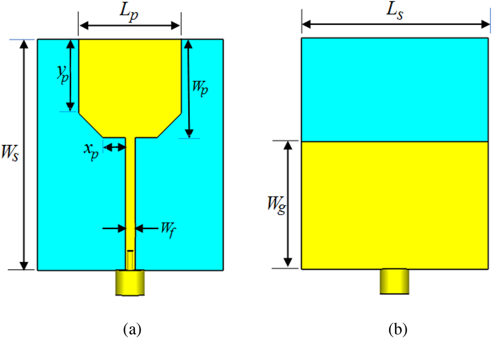
The geometrical configuration of the proposed flexible UWB antenna is depicted in Fig. 1. A radiating monopole is printed on the top layer of the substrate and a partial ground plane is printed on the bottom layer. A 50 Ω microstrip line is used to feed the proposed antenna, making a standalone printed monopole antenna. In order to make the design flexible and conformable, the proposed antenna employs a Rogers flexible material substrate, RO3003 with εr, tan δ, and thickness of 3, 0.0013, and 0.25 mm, respectively. The antenna is designed to satisfy ultra-wide bandwidth for indoor wireless communications. The optimal geometrical parameters values are as: Ls = 38 mm, Ws = 41 mm, Wg = 21 mm, Lp = 21 mm, Wp = 18 mm, Wf = 0.6 mm, xp = 5.2 mm, and yp = 15 mm.
The geometry of the proposed UWB flexible monopole antenna. (a) Top-view. (b) Bottom-view.

Operation mechanism and flexibility characteristics
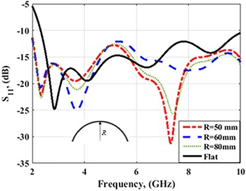
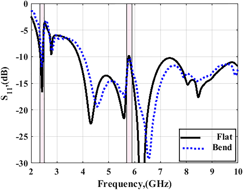
The commercial simulator, CST Microwave Studio has been used to design and evaluate the proposed antenna performance. The simulated |S 11| of the proposed antenna in a flat state (zero bending radius along the x- and y-axis) is illustrated in Fig. 2. The connector was taken into account in the simulation study. As shown in Fig. 2, the proposed antenna can achieve ultra-wide bandwidth (|S 11| < 10 dB) ranging from 2.4 to beyond 10 GHz, which covers the entire UWB bandwidth allocated by FCC (3.1 to 10.6 GHz).
Simulated |S 11| of the suggested UWB flexible monopole antenna in a flat state and when subject to bending along the y-axis.

The flexibility features of the proposed antenna depend on the flexibility properties of the substrate. As the designed antenna can be used for wearable medical applications, it should be conformal to the surfaces of different parts of the human body. To investigate this conformability and understand its impact on antenna performance, three different radii of curvature values, Ry = 50, 60, and 80 mm, were considered along the y-axis (in the Ws direction). For possible human body imitative, the curvature setup of the antenna was modeled in simulation upon a semi-cylinder filled with polystyrene (dielectric constant = 1.03) using a bending tool from CST Microwave Studio. Also, Fig. 2 shows the impedance bandwidth of the proposed antenna which is well maintained lower than −10 dB for all selected values of Ry which indicated that the resonant frequencies appear to be independent of the antenna curvature radius.
Radiation characteristics
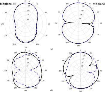
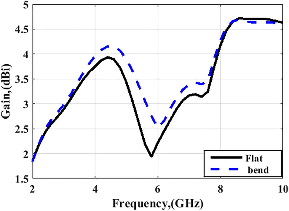
The radiation characteristics of the flexible antenna have been analyzed in simulation and taken at two frequencies, 2.45 and 5.8 GHz. The simulated normalized antenna radiation patterns in a flat state and when subject to bending for Ry = 60 mm are plotted in Fig. 3. As it can be seen, the proposed antenna has been shown robust performance to structural deformation along the y-axis. The simulated gain variations are shown in Fig. 4. The results show that the gain variations of the antenna are from 2 to 4.75 dBi within the entire frequency range.
Simulated normalized radiation patterns of the flexible antenna in a flat state (solid line) and when subjected to bending for Ry = 60 mm (dashed line) at (a) 2.45 GHz, (b) 5.8 GHz.

Simulated peak gain versus frequency of the proposed UWB flexible monopole antenna in a flat state and when subjected to bending for Ry = 60 mm.

The AMC-backed antenna design
To extend the potential applications of the proposed flexible antenna to wearable on-body communications by reducing the back radiation on the human body, the antenna was integrated with a textile AMC surface to behave like a high-impedance plane. In this section, the design methodology of the AMC unit-cell and the effect of backing the proposed antenna with a surface of a 4 × 4 unit-cell array in terms of impedance matching and antenna reflection coefficient |S 11| performance for both flat and bend states are investigated.
Design methodology of AMC unit-cell
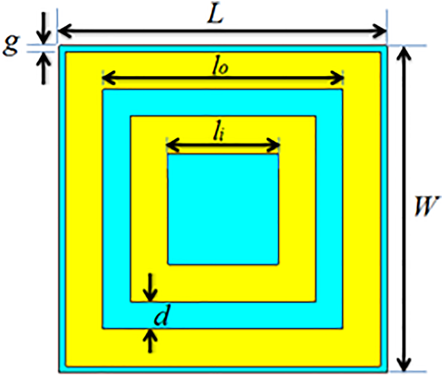
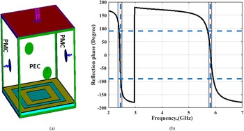
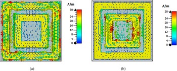
The geometrical configuration of the proposed AMC unit-cell is depicted in Fig. 5. It consists of a dual square-loop structure. Such a configuration generates two different frequencies corresponding to the capacitance/inductance arising by each loop. The AMC unit-cell was constructed on pure cotton fabric with the dielectric constant of εr = 1.7 and thickness of 1.8 mm (stack of two layers). The optimized cell dimensions to resonate at 2.45 and 5.8 GHz are listed in the caption of Fig. 5. These two frequencies were determined by the reflection phase behavior of the AMC surface. Figures 6(a) and 6(b) depict the numerical simulation setup of the AMC unit-cell and the obtained reflection phase behavior. As it can be seen in Fig. 6(b), the reflection phase is crossing the zero approximately coincide with the two frequencies of interest of 2.45 and 5.8 GHz. For further understanding of the operation mechanism, the simulated distributions of surface current at both two frequencies are examined in Fig. 7. The currents are collected in the outer square-loop at 2.45 GHz and in the inner square-loop at 5.8 GHz.
Geometry and dimensions of the proposed dual square-loop AMC unit-cell (L = 25 mm, W = 25 mm, lo = 18.6 mm, li = 8.6 mm, g = 0.45 mm, and d = 2.1 mm).

AMC unit-cell (a) Numerical simulation model and (b) Simulated reflection phase of the AMC surface.

Surface current distribution of the dual square-loop AMC unit-cell at (a) 2.45 and (b) 5.8 GHz.

Operation mechanism of the integrated antenna
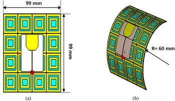
After designing the AMC unit-cell, the flexible antenna was added above 4 × 4 array surface with a separation distance of 3 mm. Such a distance has a significant impact on antenna performance and has been chosen along with array size by parametric study in terms of realized gain and radiation pattern. With 4 × 4 array size and 3 mm spacing, the overall dimensions of the integrated antenna is 99 × 99 × 4.8 mm, which is about 0.8λ 0 × 0.8λ 0 × 0.04λ 0 at 2.45 GHz. The geometry of the integrated antenna is shown in Fig. 8(a). The integrated antenna performance was examined also under a bending state with a value of Ry = 60 mm, representing arm curvature, as illustrated in Fig. 8(b). The simulation |S 11| results for the integrated antenna for flat and bent states are shown in Figs 9(a) and 9(b), respectively. As it can be seen in Fig. 9, the antenna in the two states can resonate at multi-band due to the ultra-wide bandwidth of the antenna. However, the antenna resonance bands include the two frequency bands of interest of 2.45 and 5.8 GHz, as more attractive frequencies for wearable applications.
Geometry of the proposed UWB flexible monopole antenna above 4 × 4 AMC surface. (a) Flat state. (b) Bent state with Ry = 60 mm.

Simulated |S 11| of the UWB flexible monopole antenna above 4 × 4 AMC surface at flat and bent states with Ry = 60 mm.

Performance of the integrated antenna in the vicinity of the human body
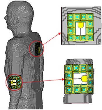
The wearable antenna can be employed in free space with good performance; however, frequency shifts can be introduced when such type of antenna operates in the vicinity of the human body, which also may harm body tissues. To evaluate these effects in simulation, the voxel-based human model (Hugo) was used to emulate a real human body. For this evaluation, the integrated antenna of both flat and bent states was attached in the vicinity of the human body model as shown in Fig. 10. As it can be seen in Fig. 10, two different parts of the human body that are suitable to mount the antenna with the two states were chosen. The first part is the human back which is suitable for integrated antenna of the flat state and the other part is the human arm which is suitable for integrated antenna of bent state (Ry = 60 mm). The integrated antenna system is placed 3 mm above the human body model for the two states. In this section, the integrated antenna performance in terms of impedance matching, radiation characteristics are investigated. For wearable safety, the SAR levels were calculated to evaluate the electromagnetic radiation leaks toward the human body.
The integrated antenna is placed on the back and arm of a CST Hugo voxel model of the human body.

Antenna matching
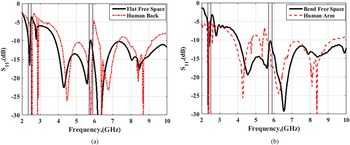
The impedance matching features of the integrated antenna of the two states were examined in terms of reflection coefficient |S 11| to show the mismatch due to the presence of human body tissues. Figures 11(a) and 11(b) show the reflection coefficient |S 11| characteristics of the integrated antenna in the vicinity of the human back and human arm, respectively. The results are shown in comparison to those evaluated in free space. Good matching for the two states of the antennas at the two operating frequencies 2.45 and 5.8 GHz has been observed.
Simulated |S 11| characteristics of the integrated antenna in the vicinity of the human back and human arm in comparison to that evaluated in free space.

Radiation characteristics
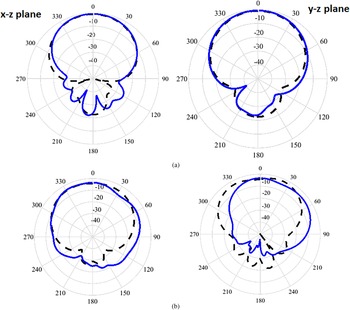
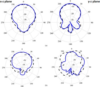
The far-field radiation characteristics of the integrated antenna at 2.45 and 5.8 GHz were simulated in xz- and yz-plane for both flat and bent states and compared to those of free space. Results in Fig. 12 show that the radiation patterns of the flat integrated antenna are slightly affected by the human back. The peak gain of the integrated antenna in the free space equals 9 dBi, while its peak gain in the vicinity of the human back equals 8.9 dBi. Results in Fig. 13 show the same scenario for the antenna subjected to bending, in which the peak gain of the integrated antenna in the free space is 8.25 dBi, while the peak gain in the vicinity of the human arm is 8.2 dBi.
Simulated radiation patterns of the flat integrated antenna placed on the human back (solid line) in comparison to that of free space (dashed line) at (a) 2.45 and (b) 5.8 GHz.

Simulated radiation patterns of the bent integrated antenna placed on the human arm (solid line) in comparison to that of free space (dashed line) at (a) 2.45 and (b) 5.8 GHz.

SAR evaluation
To fulfill its design purpose for wearable on-body communications, the integrated antenna is utilized to work in the vicinity of the human body. Since the human body is always being close to the antenna, thus, the antenna radiation effect on the body should be examined and the SAR distribution should be evaluated to ensure that its values fall at or below the acceptable level. According to the FCC, the standard value of SAR level is about 1.6 watts per kilogram (1.6 W/kg) over 1 gram of body tissue or 2.0 watts per kilogram (2 W/kg) over 10 grams of body tissue in countries that follow the Council of the European Union limit.
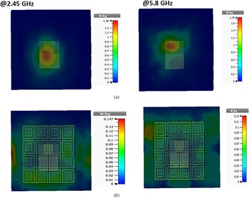
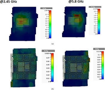
The SAR distributions of the integrated antenna at 2.45 and 5.8 GHz were evaluated for both the antenna states and compared to the standalone antenna. The power introduced to the antenna in each case equals 0.1 W. Figures 14(a) and 14(b) show the simulated averaged SAR values over 10 grams of the human back at 2.45 and 5.8 GHz for the flat antenna without and with the AMC surface, respectively. Results in Fig. 14(a) show for the standalone antenna, the SAR values are 1.36 and 1.75 W/kg at both frequencies, respectively, which are near the acceptable level of 2 W/kg. Results in Fig. 14(b) show that the SAR values of the integrated antenna are 0.147 and 0.12 W/kg at both frequencies, respectively, which fall within the acceptable level. The same fashion can be expected for the bent antenna system placed on the human arm. Figures 15(a) and 15(b) show the simulated averaged SAR values over 10 grams of the human arm at 2.45 and 5.8 GHz for the bent antenna without and with the AMC surface, respectively. Results in Fig. 15(a) show that the SAR values of the standalone antenna are 2.55 and 2.44 W/kg at both frequencies, respectively, which are above the acceptable level of 2 W/kg. Results in Fig. 15(b) show that, for the integrated antenna, the SAR values are significantly reduced to 0.0829 and 0.113 W/kg at both frequencies, respectively. From this study, it is observed that the SAR level is decreased after integrating the AMC surface with the antenna in both states.
SAR evaluation of the flat antenna placed on the human back at 2.45 and 5.8 GHz. (a) Without AMC surface. (b) With AMC surface.

SAR evaluation of the bent antenna (Ry = 60 mm) placed on the human arm at 2.45 and 5.8 GHz. (a) Without AMC surface. (b) With AMC surface.

Measurement of antenna performance characteristics
To verify the simulated results, prototypes were fabricated and tested. In this part of the work, two prototypes are tested for their performance characteristics. The first is the standalone flexible UWB antenna and the second is the complete integrated antenna (flexible UWB antenna backed by a textile AMC surface). To characterize the performance of the prototypes, two types of measurements in free space and the vicinity of the human body subjected to reflection coefficient |S 11| and far-field radiation characteristics were performed. The |S 11| was measured using a vector network analyzer Agilent N9918A to find the actual resonant frequencies of the antenna prototypes. The radiation characteristics were measured in a StarLab 18 anechoic chamber, using specific measurement fixtures, to obtain parameters such as far-field radiation patterns, gains, and radiation efficiency.
Free-space measurements
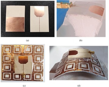
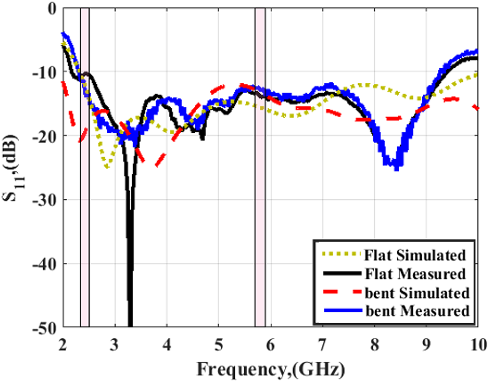
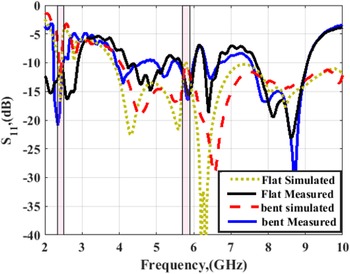
The proposed UWB flexible antenna was fabricated on Rogers RO3003 substrate and a 50Ω subminiature version A connector was integrated. A conductive layer adhesive with 0.035 mm thickness over a pure cotton fabric was used to fabricate the textile AMC surface. Photographs of the fabricated antenna prototypes without and with AMC surface in flat and bent states are shown in Fig. 16. The fabricated prototypes have been subject to measurement to validate the simulation predictions. The simulated and measured frequency responses for the antenna without and with AMC surface in flat and bent states are shown in Figs 17 and 18, respectively. As aforementioned, for the bent state the curvature radius, Ry = 60 mm was chosen as a reasonable representation for the radius of the human arm. From the two figures, good agreement between the simulated results and measured data is observed. Measured results in Fig. 17 show that the flat antenna without AMC surface achieved measured impedance bandwidth ranging from 2.4 up to 10 GHz and the impedance bandwidth of the bent antenna is also maintained. Measured results in Fig. 18 show that the integrated design in the two states maintained the two resonance frequencies of interest at 2.45 and 5.8 GHz for the two states.
Photograph of the fabricated antenna prototypes. (a) Standalone antenna in a flat state. (b) Standalone antenna in a bent state (Ry = 60 mm). (c) Integrated antenna in a flat state. (d) Integrated antenna in a bent state (Ry = 60 mm).

Simulated and measured |S 11| against frequency for the fabricated standalone antenna prototype in flat and bent (Ry = 60 mm) states.

Simulated and measured |S 11| against frequency for the fabricated integrated antenna prototype in flat and bent (Ry = 60 mm) states.

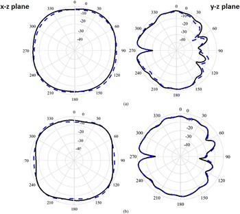
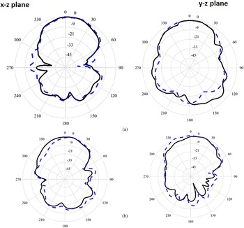
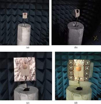
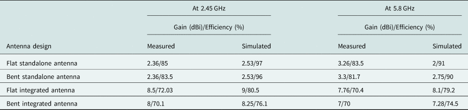
The measured radiation patterns of the antenna prototypes of the two states are then assessed in the xz- and yz-planes as shown in Figs 19 and 20 at 2.45 and 5.8 GHz, respectively. Photographs of the measurements setup are shown in Fig. 21. The measured peak gain and radiation efficiency values are listed in Table 1, which are close to the simulated values and show good agreement.
Measured 2D gain radiation patterns of the standalone antenna in the flat state (solid line) and when subjected to bending (dashed line) at (a) 2.45 GHz and (c) 5.8 GHz.

Measured 2D gain radiation patterns of the integrated antenna in the flat state (solid line) and when subjected to bending (dashed line) at (a) 2.45 GHz and (c) 5.8 GHz.

Measurement set up of radiation characteristics of the fabricated antenna prototypes inside a StarLab 18 anechoic chamber. (a) Standalone antenna in a flat state. (b) Standalone antenna in a bent state (Ry = 60 mm). (c) Integrated antenna in a flat state. (d) Integrated antenna in a bent state (Ry = 60 mm).

Simulated and measured peak gain and radiation efficiency of the proposed antenna designs at 2.45 and 5.8 GHz

On-body measurements
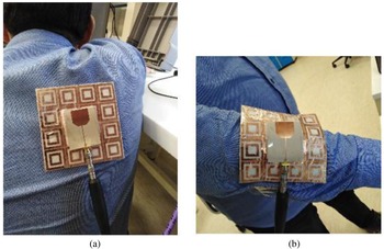
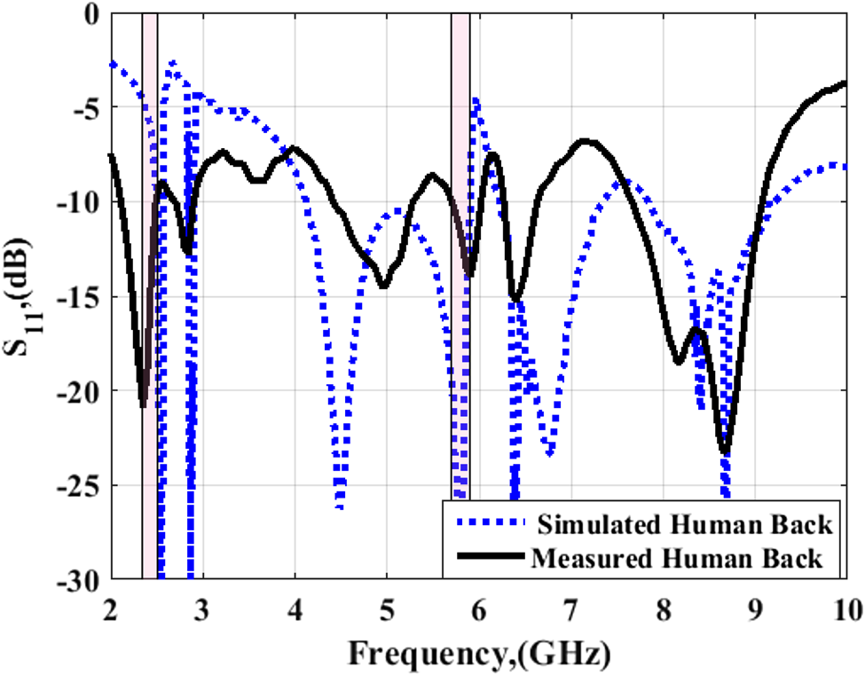
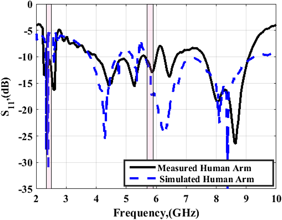
For on-body measurements, the integrated antenna prototype was placed over a human back and human arm, as displayed in Fig. 22. Reflection coefficient |S 11| characteristics were evaluated under the vicinity of the human back and arm, as shown in Figs 23 and 24, respectively. The results are shown in comparison to those obtained using Hugo human voxel model. Good performance is obtained for the two positions with small differences between the results because of the fabrication and measurement process which cannot be overcome.
On-body measurement set up of frequency response of the integrated antenna prototype placed on (a) Human back. (b) Human arm.

Simulated and measured reflection coefficient |S 11| characteristics against the frequency of the integrated antenna prototype placed on the vicinity of the human back.

Simulated and measured reflection coefficient |S 11| characteristics against the frequency of the integrated antenna prototype placed on the vicinity of the human arm.

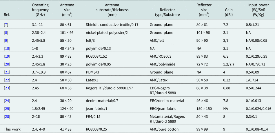
In the end, our work is compared to other designs as tabulated in Table 2. It is clear that our work has good performance, high gain, and low SAR level which enable it to be used in wearable applications.
Proposed wearable antenna versus selected recently designs

Conclusion
An integrated design consisting of a flexible antenna and a textile AMC surface spaced apart by 3 mm was demonstrated. The antenna was designed to operate over ultra-wide bandwidth ranging from 3 to 9 GHz and its flexible nature makes it convenient for a wide range of applications in the area of indoor wireless communications. While integrating the textile AMC surface makes the antenna feasible to be used for on-body communications. For design validation, an integrated model of antenna and AMC surface was implemented and tested for different operation scenarios. The antenna performance has been validated by studying the bending conditions in the vicinity of the human body. All the measured data are in good agreement with that obtained via numerical analysis. Moreover, the evaluated SAR levels show that the proposed integrated model has been achieved the safety requirements for wearable medical applications.
 Walaa M. Hassan obtained the B.Sc., M.Sc., and Ph.D. degrees from Menoufia University in 2002, 2010, and 2016, respectively. She is currently a researcher at the microwave department, electronics research institute (ERI), Egypt. Her research interests FDFD, breast cancer detection, optimization techniques, scattering problems, DRA, transmit array, reflectarray, solar cell, textile antenna, graphene, and RFID.
 Ayman Ayd R. Saad obtained the B.Sc., M.Sc., and Ph.D. degrees in electrical engineering from Minia University, Egypt in 2005, 2009, and 2013, respectively. From 2013 to 2017, he was a part-time lecturer with the Electrical Engineering Department, South Valley University, and the Electrical Engineering Department, Sohag University. He is currently the managing director of Kosseir Radio, Telecom Egypt, Egypt. He took over the projects of the upgrade of Egypt GMDSS Coastal Stations. His research interests include multiband/UWB miniaturized antennas, antenna arrays, MIMO antenna systems, millimeter-wave antennas, flexible/textile antennas, and applications of metamaterial in antenna design. Dr. Saad serves as a reviewer for many reputed journals such as IEEE Access, IEEE Transactions on Aerospace and Electronic Systems, IEEE Transactions on Industrial Electronics, IEEE Systems Journal, IET Microwave, Antennas and Propagation, IET Electronics Letters, International Journal of Antennas and Propagation, International Journal of Microwave and Wireless Technologies, International Journal of RF and Microwave Computer-Aided Engineering, Microwave and Optical Technology Letter, Engineering Reports, International Journal of Communication Systems, and many other national and international conferences.
 Ahmed A. Ibrahim (M’19, SM'20) was born in 1986. He obtained the B.Sc. degree, and M.Sc., Ph.D. in electrical engineering from the Electronic and Communication Engineering Department, Minia University, El-Mina, Egypt in 2007, 2011, and 2014 respectively. He is now an associate professor in the Electrical Engineering Department in the Faculty of Engineering Minia University. He has been a visiting professor at University Pierre and Marie Curie, Sorbonne University, Paris VI, France for 7 months and Otto-von-Guericke-Universität Magdeburg-Germany for 6 months. He has published more than 95 peer-reviewed journals and conference papers. His research has focused on miniaturized multiband antennas/wideband, microwave/millimeter components, DRA metamaterial antenna, graphene antenna, and microwave filters. Also, his research includes MIMO antennas and energy harvesting systems. Dr. Ahmed A Ibrahim is a senior member of the IEEE and a senior member in URSI also a member of the national committee of radio science in Egypt. He is currently a reviewer in, IEEE Antennas and Wireless Propagation Letters, IEEE Microwave Wireless Components, IEEE access, IET Microwave, Antenna and Propagation, IET Electronics Letters, MOTL, Analog Integrated Circuits, and Signal Processing, and many other journals and conferences. In 2020, and 2021 he was named in the top 2% of scientists in ‘A standardized citation metrics author database annotated for scientific field’/‘Updated science-wide author databases of standardized citation indicators’.