I. INTRODUCTION
Large-format monolithic microwave integrated circuit (MMIC) heterodyne arrays, with hundreds to thousands of receivers, have many exciting applications in millimeter-wave astronomy. Examples of science that would be enabled with these arrays include:
– Probing the process of star formation in galactic molecular gas clouds by mapping gas-tracing spectral lines.
– Mapping low surface brightness emission, such as large-scale structure, with existing millimeter-wave interferometers (e.g. CARMA [1]) that could be enhanced with small focal plane arrays on each telescope that would increase the field of view.
– Exploring the history of the early universe via measurements of the polarization of the Cosmic Microwave Background with a short-baseline interferometer [Reference Sieth, Lau and Voll2].
– Examining the expansion rate of the universe by mapping the Sunyaev–Zel'dovich Effect in galaxy clusters with large-format interferometers.
The requirements for all of these applications are similar: low noise, large bandwidth (≥15 GHz), and a large number of receiving elements (typically hundreds to thousands).
Previous instruments have already demonstrated the utility of hand-built cryogenic MMIC heterodyne arrays with just tens of elements (e.g. SEQUOIA [3]). The focus of the work presented here is to develop cryogenic heterodyne receivers whose assembly techniques are amenable to the fabrication of much larger arrays. The use of MMIC technology allows for all of the receiver components to be integrated into a single compact package, or MMIC module, that is easily mass-producible (see e.g. [Reference Samtleben4]). The MMIC module interfaces were chosen to maximize modularity so that malfunctioning receivers can be easily swapped. Multilayer boards provide a cost-effective way to route a high density of signals to and from the MMIC modules. The technology presented here will be implemented into a 4-pixel proof-of-concept sub-array, which is currently under construction.
The integrated MMIC heterodyne module discussed herein has demonstrated record noise temperature at W-band of 41 K over a wide bandwidth (82–100 GHz). The previous state-of-the-art for W-band MMIC heterodyne systems was SEQUOIA, which quotes a 50–80 K noise temperature over the 85–115.6 GHz band [3]. However, that design was not fully integrated. Other fully integrated W-band heterodyne receiver modules have been presented in the literature [Reference Camiade, Dourlens, Serru, Savary and Blanc5, Reference Haydl6, Reference Tessmann7, Reference Schellenberg, Chedester and McCoy8], but cryogenic noise data were not reported.
This paper is organized as follows: the MMIC module design is presented in Section II, a description of the chipsets is given in Section II(C), the MMIC module performance is summarized in Section III, and the design and performance of the multilayer signal-routing boards are shown in Section IV along with the 4-pixel sub-array concept. This work was presented in less detail at the European Microwave Conference [Reference Sieth9].
II. MMIC Module designs
Two W-band heterodyne MMIC module designs are presented: a single-sideband (SSB) receiver and a double-sideband (DSB) I-Q receiver. The SSB receiver was designed as a proof-of-concept for a large-scale cosmic microwave background interferometer [Reference Sieth, Lau and Voll2], while the DSB receiver is intended for spectroscopy and builds upon previous work [Reference Kangaslahti10].
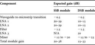
Both modules include a chain of InP MMIC low-noise amplifiers (LNAs), followed by a sub-harmonic Schottky diode mixer, which downconverts the RF signal to the intermediate frequency (IF) band. The RF input to the modules is WR-10 waveguide, which has a nominal frequency range of 75–110 GHz, but in practice does not become over-moded until 118 GHz. A waveguide-to-microstrip transition [Reference Leong and Weinreb11] precedes the LNAs and planar filters located after the LNAs provide band definition. The chips are described in detail in Section II(C) and their gain contributions to the MMIC modules are summized in Table 1.
Approximate gain contributions for individual components in the MMIC modules.

The component data are given in [Reference Leong and Weinreb11, Reference Weinreb, Lai, Erickson, Gaier and Wielgus12, Reference Samoska13, Reference Parashare14].
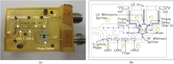
The component chips are epoxiedFootnote 1 into 0.381 mm cavities in a base block made from gold-plated brass (see Fig. 1) with a lid (not shown) that forms an RF-tight seal. The components are interconnected via gold ribbon wire bonds. While these MMIC receiver modules were both hand assembled, their split-block design is conducive to future automated assembly.
(a) Photograph of the SSB prototype MMIC module with the component chips labeled. Shown are the waveguide-to-microstrip transition, MMIC low-noise amplifiers, Schottky diode mixer, phase switch, and coaxial connectors. (b) Design drawing for the DSB MMIC receiver module. The module includes three low-noise amplifiers, a filter, an I-Q downconversion system, and miniature push-on connectors for the IF and LO.

The LNAs and mixer are biased by means of hermetic feed-through pinsFootnote 2 that connect to a printed circuit board (PCB) with bias circuitry on the reverse side of the block. A nano-miniature nine-pin strip connector provides an easy means of connecting and disconnecting the bias lines.
A) SSB module
The SSB prototype receiver module was designed for operation at a fixed local oscillator (LO) frequency of 40 GHz with instantaneous RF bandwidth from 82 to 100 GHz. The second harmonic mixer downconverts the RF signal to a 2–20 GHz (IF) band. The LO and IF interface is achieved through standard 1.85 and 2.92 mm coaxial connectorsFootnote 3 which were chosen for ease of testing the prototype. The SSB MMIC module also includes an LO phase shifter, which would be required for interferometric operation.
B) DSB module
The DSB MMIC module was implemented using an I-Q configuration, which allows for the downconversion of larger bandwidths at the expense of having to route twice as many IF signals. The I-Q downconversion is implemented with separate second-harmonic mixer chips for the in-phase and quadrature outputs. The LO signal is split and a 45° phase shift is introduced between the two signals before they reach the mixers. The requisite Wilkinson splitters and phase delays were patterned on alumina. The DSB MMIC module is intended to have a 45 GHz LO signal and accepts RF frequencies in the 75–105 GHz range. Miniature push-on connectors (Section IV(c)) were used for the IF and LO in order to enhance modularity and compactness.
C) Chip sets
1) Low-noise amplifiers
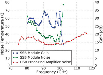
The sensitivity of the MMIC modules is dominated by the noise contribution of the low-noise amplifiers. The SSB module has two four-stage 100 nm gate length InP MMIC LNAs [Reference Weinreb, Lai, Erickson, Gaier and Wielgus12] that were fabricated by Northrop Grumman Corporation and were also used in the QUIET experiment [Reference Samtleben4]. The DSB module implements newly developed two-stage 35 nm gate length InP MMIC LNAs [Reference Samoska13], which have improved noise properties. Cryogenic noise measurements for this LNA in a waveguide package are shown in Fig. 2 with details of the testing given in Section III. The 35 nm devices have typical room temperature gains of 10–15 dB across the 75–105 GHz band as described in [Reference Samoska13]. The gain at cryogenic temperatures is expected to be roughly the same. A third LNA is required in the DSB module in order to avoid significant noise contributions from the mixer and IF amplifiers. A three-stage InP MMIC LNA with higher gain (18–20 dB across the 70–140 GHz band) [Reference Parashare14] was utilized for this.
Noise temperature and gain of the SSB prototype MMIC module at 15 K. The measurement was taken with the IF fixed at 1 GHz because of equipment limitations. The bandwidth is limited by the mixer performance. Also shown is the cryogenic noise temperature of a newly designed low-noise amplifier [13], which uses 35 nm gate length InP technology. This amplifier has been installed in the DSB MMIC receiver module.

2) Mixers
Both modules incorporate the same second-harmonic Schottky diode mixer (the DSB module uses two), which has a conversion loss of 12–20 dB. The LO signal for this mixer is sub-harmonically pumped at 40 GHz (SSB module) or 45 GHz (DSB module). It is possible to generate and route this signal much more efficiently than the 80 or 90 GHz signal that would be needed for a fundamental mixer. The mixer is the bandwidth limiting component for both MMIC modules.
3) Filters
The receiver modules include four-pole coupled line bandpass filters, which were implemented on 0.1 mm alumina substrate. The insertion loss is approximately 1.5 dB and the 3 dB bandwidth is 78–118 GHz. In the DSB module, the filter is between the second and third LNAs in order to minimize out-of-band loading at the third LNA and mixer. In the SSB module, the filter is responsible for sideband separation.
III. MMIC MODULE PERFORMANCE
Noise temperature and gain measurements of the SSB prototype module have been performed using the standard Y-factor technique where a variable thermal load (VTL) was implemented with a waveguide termination and heater. A piece of stainless steel waveguide provided a thermal break between the VTL and MMIC module. The physical temperature of the MMIC module was set at 15 K with a PID control loop while the VTL temperature was changed from 15 to 40 K. The IF was fixed at 1 GHz due to equipment limitations and was amplified and then measured with an Agilent E4446A PSA Spectrum Analyzer. The resulting cryogenic data are shown in Fig. 2, where the measurement reference plane is at the WR-10 input flange. An average noise temperature of 41 K and gain of 29 dB were obtained across the 82–100 GHz band.
Preliminary measurements of the DSB module over the 75–105 GHz band have shown a 39 K noise temperature and 19 dB gain. The improved performance is due to the upgraded front-end LNA, whose noise data are shown in Fig. 2. These noise measurements were also made with the VTL method described above. A more detailed description of the DSB module will be released in a future publication.
IV. Signal Routing
Routing the IF and LO signals is a major challenge for large-format receiver arrays. Coaxial cables and waveguide offer excellent broadband RF performance and isolation between signal paths, but they are bulky and cumbersome to install for large arrays. Instead, we have developed multilayer PCBs using a high-frequency laminateFootnote 4 These boards provide a very cost-effective and compact way to route large numbers of signals to and from the array.
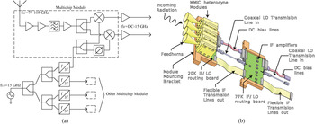
The multilayer boards will be used to construct a 4-pixel proof-of-concept array, which could be used as a building block for a much larger array. A schematic and concept drawing of this array are shown in Fig. 3. The signal routing and processing will be carried out on two stages of multilayer boards; a 20 K board that will interface directly with the MMIC modules and a 77 K board. The 20 K board will route the IF and LO signals, split the LO signal, and triple the LO frequency and the 77 K board routes the signals and provides IF amplification. Microstrip lines using flex circuit technology will provide thermal breaks between the cryostat stages and to the room temperature cryostat walls. The multilayer routing boards were prototyped in subsections: a transition from microstrip on outer layers to stripline on interior layers, the LO splitter and multiplier, the miniature push-on connectors, and the flex lines. Each of these prototype subsections are detailed below.
(a) A schematic of the signal routing scheme. (b) A concept drawing of a 4-pixel array. Multilayer PCBs route the IF and LO signals to and from the modules, with the LO being on the top layer and the IF on an interior layer. The 20 K board will include LO splitters and frequency multipliers; it interfaces with the MMIC modules via miniature push-on connectors. Thermal breaks are implemented on flex circuitry for the IF lines and stainless steel semi-rigid cable for the LO lines.

A) IF Routing
The IF routing was designed to accommodate not just the DC to 10–15 GHz IF signals from the MMIC receiver modules described in Section II, but also to permit the fabrication of future instruments that can cover 40 GHz instantaneous bandwidth (i.e. two 20 GHz IF signals for an I-Q system).
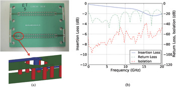
The IF signals have been routed on one of the interior layers of the board using stripline in order to reduce pixel-to-pixel cross-talk and to allow the IF and LO lines to cross. The stripline layer is accessed via stripline-to-microstrip transitons, which are illustrated in Fig. 4(a). These transitions employ coaxial vias [Reference Pillai15], where the signal via is surrounded by a number of ground vias, forming a coaxial transmission line. The ground vias also function to suppress unwanted parallel plate modes that are generated at the transition and propagate through the dielectric. A wall of vias along each side of the stripline was included to further reduce cross-talk between lines. The performance of 3.8 cm test boards with back-to-back stripline-to-microstrip transisitions is given in Fig. 4(b). The test board measurements include the performance of the test connectorsFootnote 5 which were the reference planes for these measurements. The worst-case return loss is 15 dB over the DC-20 GHz band. The insertion loss is less than 2.5 dB and the average isolation is 53 dB across the band with a peak of 39 dB for 15 mm spaced lines.
The IF will be routed on an interior layer of the routing boards for improved isolation and to allow crossing of the IF and LO signals on the board. A photograph of a stripline-to-microstrip test board is shown in (a). Each line has back-to-back stripline-to-microstrip transitions, where the lines are separated by 15 mm. The total board length is 38.1 mm. The measured performance of stripline-to-microstrip test board is plotted in (b).

B) LO Routing
The LO signals will be routed on the top layer of the multilayer routing board. A 15 GHz input signal will be split four ways, tripled in frequency, and then routed to four separate MMIC modules. The frequency multiplication is performed inside the cryostat because the 15 GHz signal is subject to lower loss than its third harmonic. The LO microstrip line has a length of approximately 5 cm and a loss of 0.36 dB/cm at 16.6 GHz. A single stainless steel semi-rigid coaxial cable will route the LO from the cryostat wall to each 20 K board, providing a thermal break as well as excellent isolation.
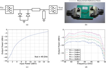
A prototype tripler is shown in Fig. 5, which is designed around an antiparallel diode pair that functions as a sinewave to squarewave converter. An inexpensive GaAs flip-chip dual diodeFootnote 6 with a 3 THz cutoff frequency was used, which lends to the mass producibility of the design. A four-pole stepped-impedance low-pass filter was implemented on the input side, with a 3 dB frequency of 23.6 GHz. The output filter is a four-pole coupled line design with a measured 3 dB bandpass of 38.5–48.3 GHz. The output power at 45 GHz is about 0.5 mW for a 63 mW input, which is the anticipated operating condition for the final array. This power is sufficient to drive the mixer. However, a marginal improvement in the mixer conversion loss could be attained with additional power. Higher output powers could be achieved by combining additional diodes in series with the existing diodes.
(a) A schematic of the prototype frequency tripler, which utilizes a flip-chip dual diode. The input filter is a stepped-impedance design. A coupled-line filter is included as a part of the output match. (b) A photograph of a prototype test board for the diode tripler. (c) Output power versus input power with the output frequency at 45 GHz. (d) Output power versus output frequency where the input power is varied between 10 and 18 dBm in increments of 2 dBm.

The tripler measurements were frequency selective as opposed to a simple power measurement. An Agilent E8257D PSG Analog Signal Generator provided the input signal and the output was measured using an unratioed receiver measurement with an Agilent E8364B PNA Series Network Analyzer. A 2.4 mm coaxial cable was connected between the signal generator and the DUT, while the output was connected directly to the 2.4 mm port of the network analyzer. A source power calibration was applied at the DUT side of the 2.4 mm cable, which was chosen as the input reference plane for these measurements. The output reference plane is at the output 2.4 mm connector. A two-port SOLT calibration was performed on the network analyzer ports as a source/receiver calibration.
The splitting is accomplished with a Wilkinson splitter that was designed with a center frequency of 15.0 GHz. The Wilkinson splitter was chosen because it is compact and is matched at all ports. The 100Ω isolation resistor is a high-frequency flip-chip resistorFootnote 7 which has an appropriately small reactance up to 50 GHz.
C) Miniature push-on connectors
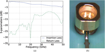
The high-frequency circuit boards mate to the modules with miniature push-on connectorsFootnote 8 which are pictured in Fig. 6. A test board was fabricated with a push-on connector that is mated to a 2.5 cm length of microstrip. A single-stub match was implemented in order to improve the connector performance at the LO frequency of 45 GHz. The test board S-parameters are shown in Fig. 6. The return loss from DC-20 GHz is better than 19 dB and at 45 GHz is better than 12 dB. The insertion loss has a maximum of 5.2 dB across the band. These connectors allow for simple connection and disconnection of the MMIC modules, which would enable malfunctioning receivers in a large-format array to be easily swapped, ensuring that there are no dead pixels. The connectors are also compact, which is conducive to designing small MMIC modules. Note that the mechanical support for the MMIC modules is not through the boards, but will be accomplished through a copper mounting structure.
(a) A plot of the measured performance of a single miniature push-on connector that mates to microstrip. The microstrip section is 2.5 cm, which will be the approximate length of the signal routing boards. (b) A photograph of the connector with a butterfly stub match.

D) Routing signals across thermal breaks
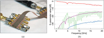
The thermal breaks in the IF will be implemented with microstrip transmission lines on flex circuit technology. A proof-of-concept test structure with a set of eight transmission lines has been constructed as shown in Fig. 7. The lines are copper with 17.5 µm thickness and 0.028 mm trace widths and a 25.4 mm ground plane on 0.127 mm polyimide substrate. The corresponding copper cross section is 0.466 mm2, which would lead to a heat load of 460 mW (290 mW) for a 7.5 cm (15 cm) line over a 20–77 K (77–300 K) temperature gradient. The line spacing for the test structure is 2.54 mm and the total length is 17 cm, which yields better than 15 dB cross talk between adjacent lines across the DC-15 GHz band. Complete S-parameter data for the test structure are shown in Fig. 7. The length of each flex line is expected to be no longer than 15 cm, for which the insertion loss would be approximately 2.8 dB. The flex lines will be connected to the board by attaching the ground plane with conductive epoxy and wire bonding the traces. The flex will attach to the cryostat wall via custom clamps, where the lines are then soldered to the connector pins.
(a) Photograph of a microstrip test structure with lines using flex circuit technology. The SMA connectors are for testing only. (b) Plot of the measured insertion loss (top line, red), return loss (green), and coupling to closest and next-nearest neighbors (middle, magenta, and bottom, blue curves) of a center line.

V. CONCLUSION
Two W-band heterodyne MMIC receiver modules have been developed for microwave astronomy applications: a SSB prototype module and a DSB module that will be part of a spectroscopic focal plane array. Across the 82–100 GHz band, the prototype SSB MMIC module has exhibited 41 K noise temperature and 29 dB gain when cooled to 15 K. Preliminary testing of the DSB module has shown a 39 K noise temperature and 19 dB gain over the 75–105 GHz band.
Signal routing to and from the MMIC modules is implemented with multilayer high-frequency PCBs and flex circuitry for the thermal breaks. Routing boards with adequate insertion loss and isolation have been demonstrated as well as a prototype frequency multiplier. The routing boards are both economical and scalable to large-format arrays. The integration of a 4-pixel receiver subarray, including DSB MMIC modules and multilayer routing boards, is currently underway.
ACKNOWLEDGEMENTS
The authors would like to thank Matt Morgan for providing the mixer design that was used in the MMIC modules, Heather Owen for invaluable help with assembly, and Richard Lai and Gerry Mei of Northrop Grumman Corporation for their development of InP HEMT processes.
This research was carried out in part by the Jet Propulsion Laboratory (JPL), California Institute of Technology, under a contract with the National Aeronautics and Space Administration. This work was supported by the JPL Strategic University Partnership Program, the National Science Foundation under grant AST-0905855, and Department of Energy contract DE-AC03-76SF00515. P.V. thanks the Harriett G. Jenkins Pre-doctoral Fellowship Program for their support.
 Matthew Sieth received his B.S. in 2007 from the Physics Department of the University of Wisconsin-Madison. He has been working at Stanford University as a Ph.D. candidate since 2007.
 Sarah Church received her B.A. in 1986 and her Ph.D. in 1991 from Cambridge University. She has been a professor at Stanford University since 1999 and served as the Deputy Director of KIPAC from 2007 to 2011. Her research interests are in observational cosmology, including Cosmic Microwave Background anisotropies and the Sunyaev-Zel'dovich Effect.
 Judy M. Lau receved her B.S. degree in engineering physics from University of California, Berkeley in 2002 and her Ph.D. in physics from Princeton University in 2007. She was a postdoctoral scholar at Stanford from 2007–2011. She is currently working at Theranos in Palo Alto, CA.
 Patricia Voll is a graduate student in Applied Physics at Stanford University, working in Professor Sarah Church's CMB instrumentation group. She is a Harriet G. Jenkins Pre-doctoral Fellowship Program Fellow and received her undergraduate degree in Physics with college honors from the University of Washington in 2007.
 Todd Gaier received the Ph.D. degree in physics from the University of California at Santa Barbara, in 1993. He is the supervisor for JPL's Microwave Astrophysics and Earth Science Systems Group. His research interests include millimeter-wave electronics for applications in astrophysics and Earth remote sensing. His group develops technologies and instruments using monolithic microwave integrated circuit (MMIC) components operating at frequencies 10–350 GHz.
 Pekka Kangaslahti received the M.Sc. and Ph.D. degrees from the Aalto University (Formerly Helsinki University of Technology), Espoo, Finland, in 1992 and 1999, respectively. He is currently with Jet Propulsion Laboratory (JPL), California Institute of Technology, Pasadena, where he designs low-noise MMIC amplifiers and receivers for astrophysics and remote sensing applications. Dr. Kangaslahti developed microwave and millimeter-wave instruments for Cassini/Huygens, Planck and Juno missions and currently focuses on receiver development for large arrays.
 Lorene Samoska received the B.S. degree in Engineering Physics from the University of Illinois in 1989, and the Ph.D. degree in Materials Engineering from the University of California, Santa Barbara, in 1995. From 1995 until 1997, she was an associate research engineer at the Electrical and Computer Engineering Department at UC Santa Barbara, where she worked on the design and fabrication of state-of-the-art InP HBT microwave digital circuits. She joined the Jet Propulsion Laboratory in 1998, where she is currently a Principal Engineer. Her research interests include the design and testing of 0.03–1 THz low-noise radiometers and power amplifiers for local oscillator sources and transmitters in future space missions.
 Mary Soria is a Senior Engineering Technical Assistant at the Jet Propulsion Laboratory in Pasadena, CA. She has over 25 years of experience in the field of hybrid microelectronics. She has contributed to the assembly, technical support, and testing of numerous atmospheric and interspace projects on lab over the last 12 years. Her specialties include microassembly of MMIC modules from 1 to 400 GHz. She is a contributing author on numerous IEEE papers, and the recipient of several NASA Tech Brief Awards.
 Kieran Cleary received his M.Eng.Sc. in electronic engineering from the National University of Ireland, Dublin, in 1994, and his Ph.D. in radio astronomy from the University of Manchester, UK, in 2004. He is currently a Senior Research Fellow at the California Institute of Technology working on the QUIET experiment to measure the B-mode of the cosmic microwave background polarization as well as the development of MMIC amplifiers and modules for radio astronomy.
 Rohit Gawande received M.Sc. degree in radio astronomy, space science from Chalmers University of Technology, Sweden and M.S. degree in Electrical Engineering from California Institute of Technology, Pasadena. He received his Ph.D. degree at University of Virginia with his dissertation work at the National Radio Astronomy Observatory, Charlottesville in 2011. He is currently a research engineer at the Dept. of Astronomy, California Institute of Technology, Pasadena. His research interests include radio astronomy instrumentation, wideband antennas and room temperature and cryogenic low-noise amplifiers.
 Anthony C.S. Readhead received the B.Sc. degree in 1967, and the B.Sc. (Hons) degree in 1968 from the University of the Witwatersrand, and the Ph.D. degree from the University of Cambridge, England, working at the Cavendish Laboratory.
He was awarded the Royal Society of London's Weir Fellowship in 1972 and spent the next 5 years alternating between the California Institute of Technology, Pasadena, and Cambridge University. He joined the Caltech Faculty in 1977. In 1981 he was appointed Professor and Director of the Owens Valley Radio Observatory: he served as Director until 1986. From 1990 to 1992 he was Executive Officer for Astronomy at Caltech. Dr. Readhead is a member of the American Astronomical Society, the Royal Astronomical Society, the National Academy of Sciences and of the American Academy of Arts and Sciences and Director of the OVRO.
 Rodrigo Reeves received his Ph.D. in electrical engineering from Universidad de Concepcion, Chile, in 2009. He was a special student in Astronomy at Caltech in 2003. He was chief engineer at the Chajnantor Observatory, host of the CBI, CBI2 and QUIET, between 2005 and 2009. He is currently a postdoc in astronomical instrumentation at Caltech. His interests include cryogenic coherent amplifiers and microwave array receivers with application in studies of the Cosmic Microwave Background and blazars from active galaxies.
 Andrew Harris received his Ph.D. in physics from the University of California at Berkeley in 1986. He is a Professor in the Department of Astronomy and an Affiliate Professor in the Department of Electrical and Computer Engineering at the University of Maryland, where he specializes in experimental astrophysics and astronomical instrumentation.
 Jeffrey Neilson received his Ph.D. degree in electrical engineering from the University of Utah, Salt Lake City in 1993. He began his engineering career in the gyrotron department at Varian Associates (Palo Alto, CA, now CPI) in 1984. From September 1994 to August 1998, he was a senior research engineer at Vista Research (Mountain View, CA), where he performed contract research in electromagnetics. Dr. Neilson joined Calabazas Creek Research (San Mateo, CA) in August 1998 and and continued his research in high-power electromagnetic component analysis. As of February 2010, Dr. Neilson has been with SLAC National Accelerator Laboratory (Menlo Park, CA) as a senior staff scientist. He is responsible for doing R&D in electromagnetics and high-power microwave components for accelerator applications.
 Sami Tantawi received the B.Sc. and M.Sc. degrees in electrical engineering from Cairo University, Giza, Egypt, in 1984, and 1987, respectively, and the Ph.D. degree in electrical engineering from the University of Maryland at College Park, in 1992.
Since 1992, he has been a Stanford Physicist with the SLAC National Accelerator Laboratory in Stanford, CA, where he has been responsible for the design and implementation of high-power RF pulse compression systems. In 2002, he became an Associate professor of particle physics and Astrophysics with SLAC, Stanford University. His research interests include vacuum electronics, high-power RF devices, modeling of RF structures, planner RF circuits, and high gradient accelerator structures. Dr. Tantawi is a Fellow of the American Physical Society. He was the recipient of the U.S. Particle Accelerator School Prize for achievements in accelerator physics and technology in 2003.
 Dan Van Winkle has a BSEL degree from Cal Poly San Luis Obispo, and an MSEE degree from Santa Clara University. He has been designing circuits in the microwave and mm wave field for the last 27 years. Dan is currently the department head of the Electronics group in the Instrument and Controls division at the SLAC National Accelerator Laboratory.