


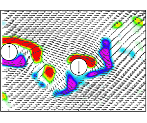

1. Introduction
Wake-induced vibration (WIV) is a fluid-elastic phenomenon that can induce transverse oscillatory motion in a bluff body placed within the wake generated by another body upstream (Assi, Bearman & Meneghini Reference Assi, Bearman and Meneghini2010). This phenomenon holds practical significance in various engineering applications (Wang, Fan & Lin Reference Wang, Fan and Lin2020; Ma et al. Reference Ma, Lin, Fan, Wang and Triantafyllou2022), including clustered offshore oil and gas production risers exposed to ocean currents (Lin et al. Reference Lin, Wang, Fan and Triantafyllou2021), overhead transmission lines exposed to wind forces (Jing et al. Reference Jing, Huang, He and Cai2021), and crossflow heat exchanger tubes (Wang et al. Reference Wang, Zhang, Hu and Zhang2023).
The WIV shares certain similarity with but also differs considerably from the well-studied phenomenon of vortex-induced vibration (VIV). The VIV is a resonant phenomenon between the moving body and its shedding vortex (Williamson & Govardhan Reference Williamson and Govardhan2004), while WIV is a more complex process involving moving bodies and a self-shedding vortex as well as an oncoming unsteady wake (Assi et al. Reference Assi, Bearman, Carmo, Meneghini, Sherwin and Willden2013). Unlike VIV's self-limited vibration amplitudes within narrow range of the reduced velocities (Fan et al. Reference Fan, Wang, Triantafyllou and Karniadakis2019), WIV exhibits a continuous increase in oscillation amplitude even at much higher reduced velocities (Lin, Fan & Wang Reference Lin, Fan and Wang2020a). Such a phenomenon is akin to classic galloping observed in non-circular bluff bodies (Novak Reference Novak1972). As a result, WIV has also been referred to as ‘wake-induced galloping’ (WIG) in the previous literature (Bokaian & Geoola Reference Bokaian and Geoola1984; Hover & Triantafyllou Reference Hover and Triantafyllou2001; Hu, Wang & Sun Reference Hu, Wang and Sun2020a), and also as ‘interference galloping’ by Ruscheweyh (Reference Ruscheweyh1983).
1.1. The WIV in the wake of a stationary cylinder
In previous studies, the typical configuration for investigating WIV involves two circular cylinders of the same diameter. The front cylinder remains stationary in the oncoming flow, whereas the other is positioned downstream and allowed to move in the crossflow direction. It has been well established that a key characteristic of WIV is that both the vibration amplitude and the frequency increase significantly as the flow velocity ( $U$) increases (Ruscheweyh Reference Ruscheweyh1983; Zdravkovich Reference Zdravkovich1985; Hover & Triantafyllou Reference Hover and Triantafyllou2001). It is important to note that
 $U$ is defined by the oncoming free stream velocity and not by a local wake profile velocity in front of the downstream cylinder.
In a series of experimental studies, the effect of  $U$ on WIV has been examined from two different perspectives. From one perspective, the reduced velocity
 $U_r$ (defined as
 $U_r=U/f_0 D$, where
 $D$ is the diameter of the cylinder, and
 $f_0$ is the natural frequency of the system in air) was considered. For example, Hover & Triantafyllou (Reference Hover and Triantafyllou2001) held a constant
 $U$ and adjusted
 $f_0$, keeping a constant Reynolds number
 $Re$ (defined as
 $Re=UD/\nu$, where
 $\nu$ is the kinematic viscosity of the fluid). They observed a single branch of response that increased monotonically with increasing
 $U_r$. From another perspective,
 $Re$ was considered. Assi et al. (Reference Assi, Bearman, Carmo, Meneghini, Sherwin and Willden2013) conducted an experiment in which a cylinder was mounted without springs, so the variation of the flow velocity led only to a change in the Reynolds number. Their experiments showed that the maximum amplitude of WIV converged to an asymptotic value that depended highly on the Reynolds number instead of the reduced velocity.
In addition to the reduced velocity and the Reynolds number, the effects of two other parameters have been investigated extensively: the structural mass-damping ratio (denoted as  $m^*\xi$, where
 $m^*$ is the ratio between the structural mass and the displaced fluid mass, and
 $\xi$ is the structural damping ratio), and the centre-to-centre gap spacing ratio between the cylinders (denoted as
 $x_0/D$, where
 $x_0$ is the distance between the centres of two cylinders).
Experiments conducted in both water (Bokaian & Geoola Reference Bokaian and Geoola1984) and wind (Hu et al. Reference Hu, Wang and Sun2020a) tunnels have provided valuable insights into the role of the structural mass-damping ratio in determining the response mode of WIV. Specifically, it was observed that when  $m^*\xi$ is small, the amplitude response continues to increase with the growth of
 $U_r$. Conversely, when
 $m^*\xi$ is large, a distinctive region of separated VIV and WIV response branches becomes evident, marked by a significant drop in amplitude at moderate
 $U_r$. Furthermore, an increase in the mass-damping ratio resulted in a reduction of the maximum amplitude of WIV, a phenomenon similar to the effects observed in VIV (Khalak & Williamson Reference Khalak and Williamson1997). The gap spacing ratio (
 $x_0/D$) between the cylinders represents another critical parameter that significantly affects the behaviour of WIV. An increase in
 $x_0/D$ has been shown to narrow the synchronization regime of WIV with respect to
 $U_r$, often reducing it to a range as narrow as that observed for VIV in the case of a single cylinder. This phenomenon has been well documented in experiments conducted by Bokaian & Geoola (Reference Bokaian and Geoola1984), Brika & Laneville (Reference Brika and Laneville1999) and Assi et al. (Reference Assi, Bearman and Meneghini2010). Notably, some interference effects persisted in certain experiments even when the gap spacing ratio exceeded 20, highlighting the complexity of the phenomenon (Brika & Laneville Reference Brika and Laneville1999).
1.2. The WIV in the wake of an oscillating cylinder
It is well-established that WIV is a form of flow-induced vibration (FIV) influenced by the instabilities present in the oncoming wake (Assi et al. Reference Assi, Bearman and Meneghini2010). As a result, we anticipate that the characteristics of WIV will vary when the oncoming wake is generated by an oscillating cylinder compared to a stationary one. Research on bluff body flows has shown that different trajectories of the cylinder can lead to significant changes in wake vortex-shedding behaviour (Carberry, Sheridan & Rockwell Reference Carberry, Sheridan and Rockwell2005; Wang, Fan & Triantafyllou Reference Wang, Fan and Triantafyllou2021). Indeed, several studies have investigated WIV in the wake of an oscillating cylinder and found that the oscillation of the upstream cylinder significantly alters fluid morphology between the bodies, leading to interference on the downstream response (Papaioannou et al. Reference Papaioannou, Yue, Triantafyllou and Karniadakis2008; Prasanth & Mittal Reference Prasanth and Mittal2009; Bao et al. Reference Bao, Huang, Zhou, Tu and Han2012; Qin, Alam & Zhou Reference Qin, Alam and Zhou2019).
Variations in gap spacing between the bodies can result in different interference mechanisms due to potential transitions in the gap flow pattern (Kim et al. Reference Kim, Alam, Sakamoto and Zhou2009; Xu et al. Reference Xu, Ji, Sun, Ding and Bernitsas2019; Hu, Wang & Sun Reference Hu, Wang and Sun2020b). Close proximity of the bodies causes intermittent reattachment of the upstream shear layer on the downstream body, influencing the presence or absence of constant or intermittent gap flow (Griffith et al. Reference Griffith, Jacono, Sheridan and Leontini2017; Qin et al. Reference Qin, Alam and Zhou2019). Gap flow acts as a trigger for large-amplitude oscillations of the downstream body (Borazjani & Sotiropoulos Reference Borazjani and Sotiropoulos2009). When the separation between the cylinders is sufficiently large, alternate vortex shedding occurs within the gap (Zhou & Alam Reference Zhou and Alam2016). In this scenario, the downstream cylinder's response differs from the galloping-like WIV response when the upstream cylinder is fixed. Specifically, the downstream oscillation amplitude ceases to increase and instead decreases with an increase in reduced velocity (Papaioannou et al. Reference Papaioannou, Yue, Triantafyllou and Karniadakis2008; Prasanth & Mittal Reference Prasanth and Mittal2009), as demonstrated by wind-tunnel (Kim et al. Reference Kim, Alam, Sakamoto and Zhou2009) and water-channel (Xu et al. Reference Xu, Ji, Sun, Ding and Bernitsas2019) experiments. However, a recent wind-tunnel experimental study by Hu et al. (Reference Hu, Wang and Sun2020b) observed a re-emergence of downstream oscillation amplitude build-up at much higher reduced velocities, providing new insights into WIV. Additionally, Lin et al. (Reference Lin, Wang, Zheng and Sun2020b) discovered a downstream frequency branch that strictly follows the upstream vortex-shedding frequency during large-amplitude vibration of the upstream body.
On the other hand, the relative difference between the diameters of upstream and downstream bodies can also significantly modify the gap flow behaviour and interference mechanism on the downstream response (Lam & To Reference Lam and To2003; Qin, Alam & Zhou Reference Qin, Alam and Zhou2017; Wang, Alam & Zhou Reference Wang, Alam and Zhou2018). Varying the diameter difference gives rise to more gap flow structures. Wang et al. (Reference Wang, Alam and Zhou2018) identified four gap flow regimes for two cylinders of different diameters, shedding light on the inter-relationship between the forces on the downstream cylinder and the physical aspects of gap flow. Regarding the oscillation of the cylinders, Qin et al. (Reference Qin, Alam and Zhou2017) identified six distinct flow regimes. They observed violent vibration on the downstream body when a cylinder of smaller diameter was placed upstream. In contrast, placing a larger cylinder upstream may lead to a shadowing effect on the downstream cylinder, suppressing the downstream vibration response (Lam & To Reference Lam and To2003). Other studies have investigated the upstream wake-interference mechanism on the downstream response, where the two cylinders were rigidly or elastically coupled (Zhao Reference Zhao2013; Sharma & Bhardwaj Reference Sharma and Bhardwaj2023; Zhu et al. Reference Zhu, Zhao, Qiu, Lin, Du and Dong2023). In such cases, synchronization is enforced on the two bodies, limiting the downstream body's ability to respond freely to the upstream wake flow.
1.3. Reduced-order modelling of WIV
The wake-displacement mechanism, as proposed by Zdravkovich (Reference Zdravkovich1977), has been widely accepted as a plausible explanation for the WIV phenomenon. According to this theory, the wake displaced by the upstream body induces a steady restoring lift force on the downstream body, even though the exact physics behind this force remains unclear. Païdoussis, Price & De Langre (Reference Païdoussis, Price and De Langre2010) employed quasi-steady analysis to demonstrate that the wake-displacement mechanism is essentially a modified version of the galloping mechanism (Den Hartog Reference Den Hartog1985). The key distinction between WIV and classical galloping lies in the fact that the former is intimately associated with a time delay, in addition to the necessary lift gradient towards the wake centreline. This time delay plays a crucial role in the WIV phenomenon. Hence Price, Païdoussis & Al-Jabir (Reference Price, Païdoussis and Al-Jabir1993) and Granger & Païdoussis (Reference Granger and Païdoussis1996) proposed modified quasi-steady models by introducing additional factors, such as memory effect and phase difference between cylinder motion and fluid force, to continuously improve the accuracy of WIV amplitude and frequency predictions.
Recently, Assi et al. (Reference Assi, Bearman, Carmo, Meneghini, Sherwin and Willden2013) introduced the concept of wake stiffness, which is modelled based on the restoration lift force measured from the experiment of two staggered stationary cylinders. The wake stiffness concept demonstrated good predictive capabilities for the frequency signature of the WIV response, particularly when wake-controlled instability dominated structural stiffness-controlled instability at higher  $U_r$. It is worth noting that Soares & Srinil (Reference Soares and Srinil2021) proposed a modified van der Pol wake oscillator model, with a wake deficit theory incorporated. While this model has provided reasonable predictions for the amplitude and frequency signature of WIV in systems controlled by both wake stiffness and structural stiffness, ongoing work seeks to enhance its accuracy, especially for higher reduced velocities and larger gap spacing ratios.
Up to now, numerous studies have focused primarily on how the downstream body responds in the wake of an oscillating cylinder, but to a lesser extent on why the downstream body responds to the upstream oscillation in that particular manner. Hence we raise the question of how WIV differs when the oncoming wake is formed by an oscillating body rather than a stationary one. And, importantly, we ask the following questions. (i) Can the properties of WIV that occur when the wake is formed by an oscillating body be explained accurately by the wake-displacement mechanism? (ii) If not, how can we reconcile all the characteristics of cylinder WIV within the wake, regardless of whether it is generated by an oscillating or stationary body?
In this paper, we conducted an experimental study on WIV with a cylinder immersed in the wake developed by another cylinder undergoing oscillation, with the intention of addressing the above questions.
2. Experimental set-up and validation
The free-vibration experiments were conducted in the free-surface recirculating water channel, shown in figure 1. The test section measured 0.3 m wide, 0.3 m deep and 1.0 m long, with glass side walls and bottom mounted on a steel frame, allowing for clear observation of models for flow visualization. The flow velocity, ranging from  $0.04\ {\rm m}\ {\rm s}^{-1}$ to
 $0.36\ {\rm m}\ {\rm s}^{-1}$, was continuously controlled by an electromagnetic flow meter. Time-resolved particle image velocimetry (PIV) facilitated flow visualization. The laser generator, positioned beside the circulating water tank, emitted a horizontal laser plane, while a CMOS camera was situated beneath the channel floor
The low-speed recirculation water tunnel: (a) schematic, (b) photograph.

The tested two circular cylinders were constructed from lightweight and rigid photopolymer material, precision-manufactured using a three-dimensional printing machine to achieve outer diameter  $D=30$ mm. To minimize end effects, the cylinders were installed with the lower end as close as possible to the glass floor of the test section, resulting in immersed length 298 mm and bottom clearance
 $h=2$ mm. The upper end of each cylinder was connected to a pair of air bearings, which were elastically mounted by springs. Each cylinder had a total oscillating mass of approximately 573.0 g, with displaced fluid mass 210.6 g, resulting in mass ratio
 $m^* = 2.72$. The structural damping ratio (
 $\xi$) and natural frequency (
 $\,f_0$) for the rear cylinder, measured from a free-decay test in air, were 0.68 % and 0.60 Hz, respectively. Figure 2 depicts a schematic representation of the one-degree-of-freedom rig on which the downstream cylinder was mounted.
Schematic representation of the one-degree-of-freedom rig holding the downstream cylinder. The free stream flows out of the page in the  $x$-axis direction.

We first conduct the preliminary experiment on a cylinder both in uniform flow and in the wake of a stationary cylinder with  $x_0/D=4.0$. The result is plotted in figure 3.
A schematic of configuration for (a) VIV and (b) WIV. Time series of displacement for approximately 50 cycles of oscillation in (c) VIV and (d) WIV. The dimensionless amplitude  $A_y/D$ and frequency
 $f/f_0$ response as a function of reduced velocity
 $U_r$ of (e,g) VIV and (f,h) WIV. Note in (e) the VIV amplitude response of the present experiments in comparison with the experiments of Assi et al. (Reference Assi, Bearman and Meneghini2010).

When comparing the displacement time series of the cylinder undergoing VIV and WIV at two reduced velocities,  $U_r=7.6$ (figure 3c) and
 $U_r = 16.4$ (figure 3d), it is evident that the VIV response exhibits a regular sinusoidal waveform with minimal variation of the amplitude from cycle to cycle. In contrast, the WIV response displays noticeable irregularities in the envelope, with deviations in amplitude between the maximum and minimum limits reaching up to 0.5 diameters.
The displacement amplitude  $A_y/D$ versus the reduced velocity
 $U_r$ was plotted, and the VIV response was compared with previous results (Assi et al. Reference Assi, Bearman and Meneghini2010), showing good agreement in terms of maximum amplitude and resonance regime. It is noted that the mass-damping ratio in the present experiment is measured at
 $m^*\xi = 0.019$, which is approximately equal to the previous experiment with
 $m^*\xi = 0.018$ (Assi et al. Reference Assi, Bearman and Meneghini2010).
To quantify the irregularity of the WIV envelope, three characteristic amplitude curves are plotted in figure 3(f):  $[y/D]_{max}$,
 $[y/D]_{min}$ (by taking an average of the 10 % highest and lowest peaks of the whole series, respectively) and
 $[y/D]$ (by taking an average of
 $[y/D]_{max}$ and
 $[y/D]_{min}$). These curves demonstrate that the mean displacement amplitude increases with reduced velocity, and so does the deviation between
 $[y/D]_{max}$ and
 $[y/D]_{min}$, indicating an increasing irregularity of the envelope. One might expect that the irregularity of the envelope is associated with the frequency aliasing. However, the power spectrum density (PSD) contours of the cylinder's vibration frequency response, shown in figure 3(h), reveal a single dominant frequency branch for WIV. This phenomenon, as noted by Assi et al. (Reference Assi, Bearman and Meneghini2010), lacks a rational explanation so far. Additionally, it is clear that the vibration frequency during WIV increases continuously with
 $U_r$, and gradually departs from the natural frequency of the system, in contrast to the locked-in behaviour observed in VIV, shown in figure 3(g).
Even though the WIV phenomenon occurs when a body is immersed in the wake of the upstream body, it does not necessarily mean that the behaviour of the downstream body is entirely associated with the upstream wake-interference mechanism. When the displacement curve of the WIV response is plotted together with that of the VIV response, as shown in figure 4(a), it can be observed that the slope for the WIV displacement curve roughly resembles a VIV resonance hump (upper branch) at approximately  $U_r=5$. Moreover, a comparison of the slopes for the VIV and WIV frequency curves, shown in figure 4(b), suggests that the WIV frequency curve follows a branch associated with
 $St=0.2$ for
 $U_r<5$, similar to the VIV response. Therefore, it is assumed that the WIV response is mainly contributed to by the vortex-resonance mechanism for the small
 $U_r$ regime.
A comparison of the dimensionless (a) amplitude response  $A_y/D$ and (b) frequency response
 $f/f_0$ as a function of reduced velocity
 $U_r$ between VIV and WIV. Note that in (a), the two cylinders WIV is divided by the dash-dotted lines into three regimes: VIV, hybrid of VIV and WIV, and pure WIV.

As  $U_r$ increases, the slopes of the displacement curves for the WIV and VIV responses diverge. However, the vortex-resonance mechanism still plays an important role at moderate
 $U_r$. It is expected that the WIV response is associated with a hybrid of the wake-interference mechanism and vortex-resonance mechanism until the end of VIV synchronization, at approximately
 $U_r = 10$. When
 $U_r$ keeps increasing, the wake-interference mechanism gradually takes over the vortex-resonance mechanism in sustaining the cylinder oscillation. Based on this assumption, three different regimes for the WIV response are classified: (i) a VIV resonance regime at approximately
 $U_r < 5$; (ii) a hybrid of VIV and WIV regimes approximately in the range
 $5 < U_r < 10$; and (iii) a pure WIV regime dominated by the wake-interference mechanism for
 $U_r > 10$.
3. Free vibration of a cylinder in an oscillating cylinder wake
To investigate the WIV response when the wake is generated by an oscillating cylinder positioned upstream, an experiment was conducted where the upstream cylinder was allowed to vibrate freely in the crossflow direction, shown in figure 5. The separation ratio between the cylinders was maintained at  $x_0/D=4.0$, the same as in the previous section. This separation distance
 $x_0/D=4.0$ was chosen for various reasons. On the one hand, it gives a WIV response that is qualitatively consistent with other larger separations (Assi et al. Reference Assi, Bearman and Meneghini2010). On the other hand, it is beyond the critical separation distance where bi-stable reattachment of the shear layers may occur, ensuring that the upstream cylinder would vibrate in a pure VIV response without interference from the downstream cylinder (Lin et al. Reference Lin, Wang, Zheng and Sun2020b). In addition, to control the synchronization response of the front cylinder undergoing VIV, and define the resonance regime, the stiffness of the spring on the upstream cylinder was adjusted. This variation in spring stiffness resulted in a broad range of natural frequency ratios for the upstream cylinder relative to the natural frequency of the downstream cylinder, i.e.
 $f_{n,u}:f_{n,d}$ spanning from
 $0.4:0.6$ to
 $1.85:0.6$. These adjustments were made to ensure that the VIV resonance response regime of the upstream cylinder would coincide with the WIV response of the downstream cylinder in different regimes.
(a) A photograph of the experimental set-up with free-vibration response of a cylinder in an oscillating cylinder wake. (b) A schematic of the experimental set-up.

Figure 6 illustrates  $A_y/D$ of both the upstream and downstream cylinders for different
 $f_{n,u}:f_{n,d}$. It is evident that the upstream cylinder exhibits a typical VIV response. As anticipated, by increasing
 $f_{n,u}:f_{n,d}$, the VIV regime for the upstream cylinder shifts to higher
 $U_r$.
Dimensionless amplitude  $A_y/D$ of the upstream and downstream cylinders vibration as a function of downstream reduced velocity
 $U_{r,d}$ for different natural frequency ratios
 $f_{n,u} : f_{n,d}$: (a)
 $0.4: 0.6$, (b)
 $0.6: 0.6$, (c)
 $0.9: 0.6$, (d)
 $1.2: 0.6$, (e)
 $1.45: 0.6$, (f)
 $1.85: 0.6$. Note that the shaded areas in red (blue) highlight the interference of a spike (drop) in the upstream response amplitude on the downstream response.

In figures 6(c)–6(f), we observe that a galloping-like WIV response (i.e. WIG), characterized by continuous amplitude increase with rising  $U_{r,d}$, does not occur when the upstream cylinder vibrates at large amplitudes. We focus on the
 $U_{r,d}$ range corresponding to the initial and lower branches of the upstream cylinder VIV, marked by red and blue shading in figure 6. A negative correlation is evident between the amplitudes of the upstream and downstream cylinders. Specifically, in the red-shaded areas, an increase in the upstream response amplitude coincides with a decrease in the downstream response amplitude. Conversely, in the blue-shaded areas, when the upstream response amplitude drops, the downstream vibration quickly returns to the WIG pattern. In addition, it is worth noting that when the jump in the amplitude of the upstream cylinder occurs at higher
 $U_{r,d}$, the downstream amplitude experiences a more significant drop. In contrast, at lower
 $U_{r,d}$, the jump in the upstream amplitude has minimal impact on the downstream cylinder response, as shown in figures 6(a) and 6(b). These observations align with the classification of WIV regimes, suggesting that the vibration of the upstream cylinder affects the WIV response, especially when the vibration of the downstream cylinder is influenced by the wake-interference mechanism.
To gain insight into the dynamics of the downstream WIV response in the frequency domain, figure 7 presents the normalized PSD plots of the downstream vibration frequency response at various  $U_{r,d}$. Notably, in contrast to a typical WIG response (where the upstream body remains stationary), the downstream vibration induced by the wake of a vibrating upstream cylinder exhibits two distinct frequency components in most cases. One of these components, in red, aligns with the frequency response of WIG. The other component, in green, assuredly coincides with the vibration frequency of the upstream cylinder.
Dimensionless frequency spectrum of the downstream cylinder vibration as a function of reduced velocity  $U_{r,d}$ for different natural frequency ratios
 $f_{n,u} : f_{n,d}$: (a)
 $0.4: 0.6$, (b)
 $0.6: 0.6$, (c)
 $0.9: 0.6$, (d)
 $1.2: 0.6$, (e)
 $1.45: 0.6$, (f)
 $1.85: 0.6$. Note that the green dashed lines locate the frequency branch of WCV; the red dashed lines locate the frequency branch of WIG.

While direct velocity fluctuation measurements in the upstream wake were not conducted, it is likely that the component aligning with the upstream vibration frequency is due to periodic force excitation via vortices shed from the vibrating upstream body. This observation is consistent with the occurrence of upstream VIV response, indicating a synchronization between the upstream vortex-shedding frequency and the cylinder oscillation frequency. Consequently, we refer to this component as ‘wake-captured vibration’ (WCV). Furthermore, as observed in figures 7(c)–7(f), the appearance of the WCV frequency branch is generally accompanied by the presence of broadband frequency components around the WIG frequency branch. This suggests a competition between WIG and WCV. Once the VIV synchronization of the upstream cylinder ceases, only the WIG frequency branch remains in the PSD plot of the downstream vibration.
Figure 8 shows the normalized PSD plots of lift force measured on the downstream WIG and WCV responses. It is evident that the downstream oscillation is contributed by two forcing components of different frequencies. The lower forcing is synchronized with WIG, expected to be associated with the synchronization between the structure and downstream wake (Soares & Srinil Reference Soares and Srinil2021); the other forcing is synchronized with the upstream wake vortex-shedding frequency, and is surely attributed to the upstream wake instabilities. For the WIG phenomenon, it is seen that the forcing associated with WIG tends to be predominant with reduced velocity increasing. As the cylinder vibration turns into WCV, a jumping of predominant forcing of WIV from the WIG branch to the upstream wake frequency branch can be clearly noted, with the WIG forcing almost vanishing. This phenomenon indicates that the mechanism of WIV transitions from the downstream synchronization to the upstream wake instabilities as the upstream cylinder vibrates at higher amplitudes. When the WCV regime ends, the forcing related to WIG regains dominance. The above results imply that there are two types of interference mechanism related to WIG and WCV in competition, depending on the upstream cylinder oscillation. Given a strong relativity between the dynamics of cylinder vibration in WCV and the instability of the upstream wake, WCV is interpreted as the downstream dynamics being captured by the upstream wake.
Normalized frequency spectrum of lift force as a function of reduced velocity for the downstream cylinder in the regime of (a) WIG and (b) WCV.

These observations suggest that when the wake is generated by a vibrating body with a large amplitude, the downstream body's dynamics is characterized by WCV rather than exhibiting a WIG or VIV response.
4. Wake-induced force on a static cylinder and linear stability analysis
To assess the influence of upstream cylinder oscillation on the hydrodynamic forces acting on the downstream cylinder, we refer to the research conducted by Païdoussis et al. (Reference Païdoussis, Price and De Langre2010) and Assi et al. (Reference Assi, Bearman, Carmo, Meneghini, Sherwin and Willden2013), which emphasized the role of the gradient of steady lift in sustaining the oscillatory instability of WIV. The experimental set-up and cases are shown in figure 9. The experiment was carried out on a towing tank of length 10 m and a  $1\ {\rm m}\times 1\ {\rm m}$ test section. The carriage is installed on two rails aligned with the tank length. On the carriage, a three-degrees-of-freedom stage is installed, allowing trajectories of crossflow (perpendicular to the towing direction) motion. The software of the experimental facility is developed with integrated capability of the motion update and trajectory monitoring (Power PMAC system), force measurement (NI DAQ-USB6218 with an ATI-Gamma 6-axis force sensor). In the current experimental set-up, the two rigid cylinder models are mounted on the carriage, piercing the water. The upstream cylinder is mounted at the linear stage, allowing crossflow motion with prescribed amplitudes and frequencies, and the downstream cylinder is fixed at the non-moving part of the carriage as a stationary rigid cylinder. The prescribed amplitudes and frequencies for the upstream oscillation are in the ranges
 $A_u/D\in [0.25, 1.0]$ and
 $f_uD/U\in [0.04, 0.22]$ covering the possible amplitudes and frequencies of VIV resonance. Measurement of fluid forcing is carried out for the stationary downstream cylinder traversed across 272 points in and out of the wake-interference region (each point has been marked in figure 9c). The cylinders are towed at a fixed velocity
 $U=0.2\ {\rm m}\ {\rm s}^{-1}$, thus achieving
 $Re=7620$.
(a) A photograph of the experimental set-up with wake-induced force on a cylinder in an oscillating cylinder wake. (b) A schematic of the experimental set-up. (c) A schematic of downstream fluid force measurements across 272 positions (each position marked by a point).

In figure 10, we present a graphical representation of the steady lift and drag forces experienced by the downstream cylinder in response to the upstream cylinder's forced vibration at the same frequency but with different amplitudes. Positive values of  $C_y$ indicate a lifting force directed towards the wake centreline. Here are several key observations.
(i) There is a consistent steady lift component that draws the body towards the wake centreline, regardless of its position.
(ii) An area of intense steady lift coefficient is evident away from the wake centreline.
(iii) The oscillation amplitude of the upstream cylinder significantly affects the value and location of the maximum steady lift coefficient.
Contours of (a,c,e,g) steady lift  $C_y$ and (b,d,f,h) steady drag
 $C_x$ in the wake of an oscillating cylinder with a fixed dimensionless frequency
 $(\,f_u D)/U=0.1$ and different dimensionless amplitudes
 $A_u/D$: (a,b) 0, (c,d) 0.25, (e,f) 0.5, (g,h) 0.85. The insets highlight the force response at
 $x_0/D=4.0$. Note that in (a i) and (b i), the force
 $C_{y,s}$ and
 $C_{x,s}$ (for the stationary upstream cylinder) is plotted as a function of dimensionless transverse displacement
 $y_0/D$; in (c i–h i), the force
 $C_{y,v}$ and
 $C_{x,v}$ (for the oscillating upstream cylinder) is plotted in comparison with
 $C_{y,s}$ and
 $C_{x,s}$. The black dashed line indicates an equivalence between
 $C_{y,v}(C_{x,v})$ and
 $C_{y,s}(C_{x,s})$.

For instance, in figures 10(a,c,e,g), as the upstream cylinder's oscillation amplitude increases from 0 to  $0.85 D$, the transverse offset of the maximum steady lift force area from the wake centreline increases from
 $0.5D$ to
 $1.25 D$. The maximum steady lift coefficient decreases slightly.
Moreover, there are two regions of intense steady lift coefficient when the upstream cylinder is stationary. However, when the upstream cylinder oscillates with a large amplitude, only one region of intense steady lift coefficient is observed. This phenomenon is likely related to the wake-interference mechanism (Armin, Khorasanchi & Day Reference Armin, Khorasanchi and Day2018), which exhibits two modes: ‘shear layer reattachment’ and ‘wake vortex interference’ when the upstream cylinder is at rest. However, when the upstream cylinder oscillates with a large amplitude, the vortex-shedding point is displaced from the wake centreline, preventing shear layer reattachment.
Regarding the steady drag coefficient, it is significantly reduced compared to the drag on a cylinder placed in a free stream due to wake shielding (Sun et al. Reference Sun, Li, Yang, Hou and Bernitsas2023). Furthermore, the closer the downstream body is to the wake centreline, the smaller the steady drag. The minimum steady drag is found near the wake centreline, close to the upstream cylinder. The oscillation amplitude of the upstream cylinder also impacts the steady drag distribution. A region of zero or negative steady drag is identified when the cylinders are close together with the upstream cylinder at rest. This region of zero or negative steady drag also emerges when the upstream cylinder oscillates with amplitude  $A_u/D=0.85$.
In our study, we focus on the case  $x_0/D=4.0$. We extract the steady lift and drag forces at
 $x_0/D=4.0$, highlighted by a red dashed line in figure 10(a), and illustrate them as functions of the transverse displacement from the centreline of the wake in the insets of figure 10. Several key observations are as follows.
(i) With the upstream cylinder kept stationary, figure 10(a i) shows an almost linear relationship between the steady lift coefficient
 $C_{y,s}$ and the transverse displacement from the wake centreline $y_0/D$. The gradient of $C_{y,s}$ with respect to $y_0/D$ is approximately 0.63, which is closely aligned with the value of 0.65 reported by Assi et al. (Reference Assi, Bearman and Meneghini2010).
(ii) Comparing the steady lift when the upstream cylinder is oscillating (
$C_{y,v}$) with that for the stationary upstream cylinder ($C_{y,s}$), an increase in the oscillation amplitude of the upstream cylinder results in a significant reduction in the slope of $C_{y,v}$. When the upstream cylinder's oscillation amplitude reaches $0.85 D$, the slope of the steady lift $C_(y,v)$ is close to zero.


In addition to examining the effects of upstream cylinder amplitude, we also investigate the influence of upstream oscillation frequency on the hydrodynamic forces acting on the downstream cylinder. Figure 11 presents the variations in  $C_{y}$ and
 $C_{x}$ on a stationary downstream cylinder while the upstream cylinder oscillates at different frequencies but with the same amplitude. The results clearly indicate that an increase in the upstream oscillation frequency corresponds to an increase in the gradient of
 $C_{y,v}$ relative to
 $C_{y,s}$, and a decrease in the average drag coefficient. These results revealed a strong dependency of the downstream hydrodynamic properties on a combination of the upstream body's vibration amplitude and frequency.
Contours of (a,c,e,g) steady lift  $C_y$ and (b,d,f,h) steady drag
 $C_x$ in the wake of an oscillating cylinder with a fixed dimensionless amplitude
 $A_u/D=0.5$ and different dimensionless frequencies
 $(\,f_u D)/U$: (a,b) 0.1, (c,d) 0.14, (e,f) 0.18, (g,h) 0.22. The insets show the force
 $C_{y,v}$ and
 $C_{x,v}$ (for the oscillating upstream cylinder) in comparison with the force
 $C_{y,s}$ and
 $C_{x,s}$ (for the stationary upstream cylinder), at
 $x_0/D=4.0$. The black dashed line indicates an equivalence between
 $C_{y,v}(C_{x,v})$ and
 $C_{y,s}(C_{x,s})$.

Based on the findings regarding the hydrodynamic forces with the static cylinder downstream of an oscillating cylinder, a theoretical mode by integrating the linear instability analysis and quasi-steady assumption of WIV is applied to explain the loss of WIG in competition with WCV when the upstream cylinder vibrates at higher amplitudes. This analysis underscored the significance of the lifting force gradient for WIV. Specifically, considering an elastically mounted rigid cylinder situated within the wake of a rigid upstream body undergoing harmonic motion of one degree of freedom in the crossflow direction, the governing equation governing the dynamics of the cylinder can be expressed as
 \begin{equation} m\ddot{y} + c\dot{y} +ky = F_y, \end{equation}
where  $m$,
 $c$ and
 $k$ are the mass, damping and stiffness of the moving system, respectively,
 $F_y$ is the fluid lift force, and
 $y$ is the crossflow displacement. The approaching flow velocity
 $\hat {U}$ is properly adjusted by taking into account the velocity of the cylinder
 $\dot {y}$, shown in figure 12, and can be expressed as
 \begin{equation} \hat{U} = \sqrt{\dot{y}^2 + U_{\tau}^2}, \end{equation}
(a) A schematic of cylinder WIV in an upstream cylinder wake. (b) Velocity and fluid forces vector diagram of the downstream cylinder.

where  $U_{\tau }$ is the local wake velocity. According to quasi-steady theory, the fluid forces acting on the oscillating cylinder approximate the static fluid forces at each displacement of the cylinder during oscillation. Therefore, the lift force
 $F_y$ can be expressed as
 \begin{equation} F_y =-\frac{1}{2}\,\rho \hat{U}^2LD\left(C_x\,\frac{\dot{y}}{\hat{U}}+ C_y\,\frac{U_{\tau}}{\hat{U}}\right), \end{equation}
where  $C_x$ and
 $C_y$ are the static drag and lift coefficients, respectively. Expanding
 $C_y$ about the equilibrium position of the cylinder (i.e. the wake centreline) in linearized form, it can be expressed as
 \begin{equation} C_y = C_{y0} + \frac{\partial C_y}{\partial x}\,x + \frac{\partial C_y}{\partial y}\,y. \end{equation}
After substituting (4.4) into (4.3), and assuming that the cylinder of a symmetric geometrical configuration ( $C_{y0} = 0$ and
 ${\partial C_y}/{\partial x} = 0$) undergoes transverse motion with a fixed streamwise separation, we reach the following expression for
 $F_y$:
 \begin{equation} F_y =-\frac{1}{2}\,\rho U_{\tau} \hat{U} LD \left( \frac{\partial C_y}{\partial y}\,y + C_x\,\frac{\dot{y}}{U_{\tau}} \right). \end{equation}
Furthermore, it is widely acknowledged that there is a time lag between fluid-dynamic forces and cylinder displacement, attributed to vortex–structure interactions. As an initial approximation (Price & Païdoussis Reference Price and Païdoussis1984), this time delay, denoted as  $\delta$, can be expressed as
 \begin{equation} \delta = \frac{\mu D}{U_{\tau}}, \end{equation}
where  $\mu \sim O(1)$ is is associated with cylinder motion and the convection of local viscous effect downstream (Granger & Païdoussis Reference Granger and Païdoussis1996). Therefore, assuming harmonic motions, i.e.
 $y = {\rm e}^{{\rm i}\omega t}$, and inserting the time lag (i.e.
 ${\rm e}^{-{\rm i}\omega \delta }$) into (4.5), (4.1) can be written as
 \begin{equation} \ddot{\tilde{y}} + R\dot{\tilde{y}} + H\tilde{y} = 0, \end{equation}
where
 \begin{equation} \left.\begin{gathered} R = \left[ \frac{1}{2} \left( \frac{\rho \hat{U} DL}{m} \right) C_x \omega + \frac{\zeta}{\rm \pi}\,\omega_n \omega - \frac{1}{2} \left( \frac{\rho U_{\tau} \hat{U}L}{m} \right) \left( \frac{\partial C_y}{\partial y} \right) \sin\left( \mu\, \frac{\omega D}{U_{\tau}} \right) \right], \\ H = \left[ \omega_n^2 + \frac{1}{2} \left( \frac{\rho U_{\tau} \hat{U}L}{m} \right) \left( \frac{\partial C_y}{\partial y} \right) \cos\left( \mu\,\frac{\omega D}{U_{\tau}} \right) \right], \end{gathered}\right\} \end{equation}
where  $\tilde {y} = {y}/{D}$ is the non-dimensional crossflow displacement,
 $\zeta$ is the logarithmic decrement, and
 $\omega _n$ is the radian natural frequency of the system. An oscillatory instability will arise when the damping item
 $R$ becomes negative. Therefore, presuming that
 $\mu \omega D/U_{\tau }$ is sufficiently small (providing
 $\sin (\mu \omega D/U_{\tau }) \approx \mu \omega D/U_{\tau }$), the threshold of instability (i.e.
 $R=0$),
 $U_c = U_{\tau }$, is obtained as
 \begin{equation} U_c = \frac{2/{\rm \pi}}{\left( -C_x + \mu\,\dfrac{\partial C_y}{\partial y} \right)}\,\frac{m \omega_n \zeta}{\rho DL}. \end{equation}
Obviously, typical galloping-like WIV (i.e. WIG) can arise only if the quantity in brackets is positive,
 \begin{equation} \frac{\partial C_y}{\partial y} - \frac{1}{\mu}\,C_x > 0, \end{equation}
i.e. the gradient of lift force in the transverse direction should be positive and sufficiently large.
Based the above theory and experimental results, we quantify key hydrodynamic parameters related to WIV when the upstream cylinder is allowed to oscillate. In figure 13, we illustrate the gradient of steady lift and the average steady drag coefficient for  $x_0/D=4.0$ under various upstream response amplitudes and frequencies. It is noteworthy that when the upstream cylinder undergoes large-amplitude oscillations (i.e.
 $A_y/D=0.85$) or operates at a certain reduced frequency (
 $\,f\kern0.07em D/U=0.12$), the gradient of steady lift in the wake is significantly reduced compared to other amplitudes or frequencies. Interestingly, when identifying the region where a typical VIV response occurs in figure 13(a), it is surprising to observe that this VIV region mostly aligns with areas characterized by low gradient values of steady lift. This implies that a typical free-vibration response in WIG is unlikely to occur when the body is placed in the wake generated by a cylinder undergoing VIV.
(a) The steady lift gradient and (b) the averaged steady drag, normalized by the values for the stationary upstream cylinder, as functions of upstream oscillation dimensionless amplitude and frequency in the upstream wake at  $x_0/D=4.0$.

Regarding the steady drag in figure 13(b), it becomes evident that the average steady drag coefficient is considerably reduced when the upstream cylinder undergoes large-amplitude and high-frequency oscillations. While these presented graphs offer possibilities for actively controlling the occurrence of a galloping-like WIV response or enhancing propulsion on the downstream body through manipulation of the upstream body's oscillation amplitude and frequency, it is important to acknowledge the limitations of the presented maps in terms of data density and scope. Further research could provide more comprehensive insights into these hydrodynamic phenomena.
5. Wake-induced force on an oscillating cylinder
As depicted in the above discussion, a galloping-like WIV may not occur if the oncoming wake is generated by an upstream cylinder undergoing VIV. This is because the resonance oscillation of the upstream body with large amplitude significantly reduces the necessary gradients of the lift force in the wake to sustain the wake-displacement mechanism. Furthermore, another wake-induced instability mechanism, known as WCV, will likely capture the dynamics of the downstream body instead. This implies that the wake-displacement mechanism alone is insufficient to explain the dynamics of cylinder vibration induced by the wake of an oscillating upstream body. In this section, we introduce the concepts of energy transfer coefficient ( $C_{lv}$) and effective added mass coefficient (
 $C_{my}$) (Fan & Triantafyllou Reference Fan and Triantafyllou2022) to amalgamate the characteristics of a cylinder's WIV, regardless of whether the upstream cylinder is in oscillation or at rest.
We also start from (4.1) of an elastically mounted cylinder undergoing harmonic motion in the transverse direction. Considering that the cylinder motion  $y(t)$ and fluid force
 $F_y (t)$ are synchronized and are typically well approximated by sinusoidal functions (as discussed above, whether in WIG or WCV, there is a synchronization between the cylinder motion and fluid force acting on the body), we have
 $$\begin{gather} y(t) = A_0 \cos(2{\rm \pi} ft), \end{gather}$$
 $$\begin{gather}F_y (t) = F_0 \cos(2{\rm \pi} ft + \phi), \end{gather}$$
where  $f$ is the oscillation frequency,
 $A_0$ and
 $F_0$ are the amplitude of the cylinder motion and fluid force, respectively, and
 $\phi$ is the phase difference between the cylinder motion and fluid force. Therefore, the fluid force can be decomposed into a component in phase with the cylinder velocity
 $F_v$ and a component in phase with the cylinder acceleration
 $F_a$:
 \begin{align} F_y (t) &= F_0 \cos(2{\rm \pi} ft + \phi) \nonumber\\ &=-F_a \cos(2{\rm \pi} ft) - F_v \sin(2{\rm \pi} ft), \end{align}
where  $F_a = -F_0 \cos (\phi )$ and
 $F_v = F_0 \sin (\phi )$.
Hence (4.1) can be rewritten as
 \begin{equation} \left(m + \frac{F_a}{4A_0 {\rm \pi}^2 f^2}\right) \ddot{y} + \left(c + \frac{F_v}{2A_0 {\rm \pi}f}\right) \dot{y} + ky = 0 . \end{equation}
The terms related to  $F_a$ and
 $F_v$, properly non-dimensionalized, provide the added mass coefficient
 $C_{my}$ and the lift coefficient in phase of velocity
 $C_{lv}$, respectively:
 $$\begin{gather} C_{my} = \frac{F_a}{A_0 {\rm \pi}^3 f^2 D^2 \rho L}, \end{gather}$$
 $$\begin{gather}C_{lv} = \frac{2F_v}{\rho D U^2 L}. \end{gather}$$
Equation (5.4) indicates that  $C_{lv}$ quantifies the energy transfer from the fluid to the cylinder, and
 $C_{my}$ quantifies the variability of the added mass coefficient, affecting the system's natural frequency. By employing a forced-vibration experiment with a cylinder controlled to vibrate sinusoidally, transverse to the wake of an oscillating upstream cylinder, we generate contour plots of the fluid forcing
 $C_{lv}$ and
 $C_{my}$, in a plane of dimensionless amplitude (
 $A_y/D$) and dimensionless frequency (
 $\,f\kern0.05em D/U$) of the downstream cylinder oscillation, as shown in figures 14 and 15, respectively. The dimensionless frequency is equivalent to the reciprocal of true reduced velocity (
 $V_r = U/f\kern0.05em D$). These contour plots distinctly show the variation of
 $C_{lv}$ and
 $C_{my}$ as functions of the cylinder oscillation amplitude and frequency when it oscillates in the wake of an upstream cylinder undergoing VIV. The contour plots of
 $C_{lv}$ and
 $C_{my}$ for a cylinder oscillating in a uniform flow are also presented for comparison.
Contours of  $C_{lv}$ as functions of
 $A_y/D$ and
 $f\kern0.05em D/U$ for the oscillating cylinder: (a) in the uniform flow; (b) in the wake of a stationary cylinder; (c) in the wake of a cylinder undergoing a possible VIV response with
 $A_u/D=0.25$ and
 $(\,f_u D)/U=0.1$; (d) with
 $A_u/D=0.5$ and
 $(\,f_u D)/U=0.125$; (e) with
 $A_u/D=0.75$ and
 $(\,f_u D)/U=0.175$; (f) with
 $A_u/D=1.0$ and
 $(\,f_u D)/U=0.2$. The red lines highlight the path of
 $C_lv=0$. The black points represent amplitude and frequency response measured from free-vibration experiments.

Contours of  $C_{my}$ as functions of
 $A_y/D$ and
 $f\kern0.05em D/U$ for the oscillating cylinder: (a) in the uniform flow; (b) in the wake of a stationary cylinder; (c) in the wake of a cylinder undergoing a possible VIV response with
 $A_u/D=0.25$ and
 $(\,f_u D)/U=0.1$; (d) with
 $A_u/D=0.5$ and
 $(\,f_u D)/U=0.125$; (e) with
 $A_u/D=0.75$ and
 $(\,f_u D)/U=0.175$; (f) with
 $A_u/D=1.0$ and
 $(\,f_u D)/U=0.2$. The blue lines highlight the minimum value of
 $C_{my}$ attainable in the plots. The amplitude and frequency response measured from free-vibration experiments is identified by black points.

Shown in figure 14, a positive value of  $C_{lv}$ suggests that the fluid inputs energy to the body motion, while a negative
 $C_{lv}$ indicates that the fluid damps the body motion. For the cylinder oscillating in the uniform flow in figure 14(a), the positive
 $C_{lv}$ regime is limited to
 $A_y/D < 0.75$ and
 $f\kern0.05em D/U \in [0.125, 0.18]$, indicating that the fluid yields positive energy transfer to the body motion, thus promoting free vibration of the body, but only at amplitudes below approximately
 $0.75D$.
However, for the cylinder oscillating in the wake of an upstream cylinder, a much broader positive  $C_{lv}$ regime arises, in which a positive
 $C_{lv}$ is attained persisting to high amplitudes and reduced velocities, such as the case of a static upstream cylinder shown in figure 14(b). This suggests that free vibration of the cylinder in the wake of an upstream cylinder will gain energy from the fluid persisting to high reduced velocities, resulting in higher amplitudes at higher reduced velocities.
Nevertheless, with an increase in the upstream oscillation amplitude, the positive  $C_{lv}$ regime at high reduced velocities tends to shrink towards the lower amplitudes, and gradually approaches the pattern arising on the body oscillating in the uniform flow. The intriguing observation is that the wake generated by a vibrating cylinder with large amplitude shapes the fluid forcing of the downstream body in a similar way as the uniform flow. This phenomenon is attributed to the formation of a ‘2P’ vortex pattern in the upstream wake, as will be discussed further by a PIV measurement later.
In figure 15, we illustrate  $C_{my}$ difference of a cylinder placed in the different incoming flow condition. In a potential flow, the added mass coefficient of a cylinder takes nominal value 1. However, when the cylinder oscillates in a flow field, the effective added mass coefficient can vary significantly with the amplitude and frequency of the cylinder, as a result of the alternation in the relative motion between the structural motion and the wake vortex formation (Wang et al. Reference Wang, Fan and Triantafyllou2021).
As depicted in figure 15(a), when the cylinder oscillates in the uniform flow, the added mass coefficient can range from as low as  $-0.5$ to exceeding a value of 2.1, depending on the cylinder oscillation amplitude and frequency. On the other hand, when the cylinder oscillates in the wake formed by an upstream one, the variation in the added mass coefficient tends to be more striking. Figure 15(b) shows that the added mass coefficient continually decreases with decreasing frequency, and can be as low as
 $-2.1$. This result implies that the effective added mass force acting on the downstream body is significantly modified by the wake vortices generated by the upstream one.
Moreover, a comparison of the contour plots for different upstream oscillation amplitudes reveals that an increase in the upstream amplitude significantly reduces the minimum value of the added mass coefficient attainable. For instance, the minimum added mass coefficient increases from  $-2.1$ to
 $-0.3$ as the upstream cylinder amplitude increases from 0 to
 $1D$. However, it is observed that the variation of upstream vibration amplitude has little effect on the maximum added mass coefficient value attainable for the downstream cylinder, which is much lower than that for a body immersed in the uniform flow. Another notable phenomenon different from the cylinder oscillating in the uniform flow is that the added mass coefficient shows strong dependence on the cylinder oscillation frequency but is almost independent of the amplitude at high reduced velocities.
6. Prediction of WIV by forced-vibration hydrodynamics database
As mentioned above,  $C_{lv}$ quantifies the energy transfer from the fluid to the cylinder, and
 $C_{my}$ quantifies the variability of the added mass coefficient, affecting the system's natural frequency. Specifically, shown in (5.4), a stable free vibration of the cylinder will arise when the damping item equals zero. That is, the energy of vibration dissipated by the system damping must be compensated by the energy from the fluid. Moreover, the natural frequency of the free vibration can be defined as
 \begin{equation} f_{n, m} = \frac{1}{2{\rm \pi}}\,\sqrt{\frac{k}{m + m_a}}, \end{equation}
where added mass of the cylinder is  $m_a = C_{my} ({\rho {\rm \pi}D^2L}/{4})$.
As  $C_{lv}$ quantifies the energy transfer from the fluid to the structural motion, we are readily able to use the fluid forcing obtained by controlled vibration to predict a possible WIV response of the cylinder, from an energy balance point of view for a freely vibrating system. Therefore, we plot the amplitude and frequency data measured from our WIV experiments on the contour plot of the fluid forcing
 $C_{lv}$ obtained by our forced-vibration experiments, as shown in figure 14.
A good coincidence between the path of free-vibration points and the line of  $C_{lv} = 0$ in the contour map is identified for different upstream oscillation amplitude cases studied herein. Surprisingly, even though the free-vibration response of the downstream cylinder is significantly contributed by the WCV mechanism when the upstream cylinder undergoes large-amplitude oscillations, our forced-vibration fluid forcing contours can also map the free-vibration response rather well. This implies that the forced-vibration fluid forcing can accurately quantify the properties of energy transfer between the fluid and structural oscillation, whether the oscillation is attributed to a WIG mechanism or a WCV mechanism. It is also noted that the free-vibration points slightly deviate from the line of
 $C_{lv} = 0$ on the positive side. This departure is attributed to our free-vibration system involving some structural damping.
Similarly, we also plot the amplitude and frequency response of free vibration on the contours of the forced-vibration fluid forcing  $C_{my}$, as shown in figure 15. The variability of the added mass coefficient can be quantified for the free-vibration response based on these contour plots. According to the added mass coefficient, an actual natural frequency of the cylinder placed within the upstream wake can be determined.
When a direct comparison was made between the actual natural frequency and the body free-vibration frequency, as shown in figure 16, an almost linear proportion of one to one is observed between the two frequencies. The coincidence of the free-vibration frequency with the actual natural frequency suggests that galloping-like WIV is a type of resonance. Consequently, for the frequency response of the vibration induced by the oscillating body wake, one frequency component associated with WIG can be predicted by the added mass coefficient portrait. Another frequency component of WCV is determined by the upstream wake vortex-shedding frequency.
The dimensionless frequency response of cylinder WIV predicted by added mass coefficients ( $\,f_{n,m}D/U$) in comparison with those measured from free-vibration experiments (
 $\,f\kern0.05em D/U$) for the upstream cylinder undergoing a possible VIV response with different amplitudes.

Additionally, the resonance mechanism of WIV may also help to answer the question: why are there differences in the frequency responses between WIVs of low mass ratio body and high mass ratio body?
According to (6.1), it is obvious that the variation in the added mass coefficient can significantly modify the actual natural frequency of the body with low mass ratio (e.g.  $m^* \sim O(1)$) but is negligible for the body with high mass ratio (e.g.
 $m^* \sim O(100)$). As a result, the WIV response frequency gradually departs from the natural frequency of the body in vacuo for the low mass ratio body (e.g. Assi et al. Reference Assi, Bearman and Meneghini2010), but persistently maintains at the natural frequency of the body in vacuo for the high mass ratio body (e.g. Hu et al. Reference Hu, Wang and Sun2020b).
Furthermore, a direct comparison in the prediction of the galloping-like WIV frequency response was made between our added mass coefficient portrait and the wake stiffness concept proposed by Assi et al. (Reference Assi, Bearman, Carmo, Meneghini, Sherwin and Willden2013), as shown in figure 17. As can be seen, the frequency solution produced by the wake stiffness concept converges to the free-vibration frequency at high enough reduced velocities. At low reduced velocities where the oscillation is contributed by VIV resonance a lot, the wake stiffness concept yields a solution significantly departing from the measured result. However, the prediction produced by the added mass coefficient portrait yields an accurate prediction of the frequency over the entire response, even where there are multiple mechanisms of VIV, WIG and WCV involved.
The dimensionless frequency response ( $\,f\kern0.05em D/U$) of cylinder galloping-like WIV as a function of reduced velocity
 $U_r$ predicted by present added mass coefficients and wake stiffness by Assi et al. (Reference Assi, Bearman, Carmo, Meneghini, Sherwin and Willden2013) in comparison with values measured from free-vibration experiments.

7. Wake dynamics of WIV in an oscillating cylinder wake
Based on the amplitude response and hydrodynamic force results presented in the previous sections, in the following, we leverage the instantaneous vorticity maps obtained through PIV measurements within a cycle of two selected cases. Our aim is to unravel the underlying mechanisms of this dynamic interaction and offer a comprehensive explanation based on the observed flow patterns.
7.1. Enhancement effect of upstream cylinder wake
We select the case  $U_{r,d} = 11.67$ and
 $f_u/f_d = 1$ as representative of the enhanced effect of the upstream cylinder with a shedding vortex pattern ‘2S’. The vorticity snapshots at different
 $T^* = {t}/{T}$ are shown in figure 18.
Instantaneous vorticity contour of  $U_{r,d}=11.67$,
 $f_{n,u}:f_{n,d}=1:1$ obtained with PIV at times (a)
 $T^* = 0$, (b)
 $T^* = 1/4$, (c)
 $T^* = 2/4$, (d)
 $T^* = 3/4$, (e)
 $T^* = 1$. (f) Dimensionless displacement and lift of downstream cylinder.

Initially, at  $T^* = 0$, shown in figure 18(a), the downstream cylinder has just shed a clockwise vortex,
 $N_1^D$, while atop it, an anticlockwise vortex,
 $P_1^D$, begins to form, generating a downward lift and thus a downward acceleration. At this stage, the vortex shedding from the upstream cylinder shows minimal impact on the downstream cylinder.
As time advances to  $T^* = 1/4$, shown in figure 18(b), the downstream cylinder's anticlockwise vortex
 $P_1^D$ starts to detach. Concurrently, at its base, a new clockwise vortex
 $N_2^D$ begins to form, creating an upward force that leads to upward acceleration, even as the downstream cylinder continues its descent, albeit at a slower pace. Simultaneously, an anticlockwise vortex
 $P_1^U$ forms in the wake of the upstream cylinder, initiating the shedding of a clockwise vortex
 $N_1^U$.
By  $T^* = 2/4$, shown in figure 18(c), the downstream cylinder's anticlockwise vortex
 $P_1^D$ has fully detached, allowing a new anticlockwise vortex
 $P_2^D$ to emerge. At the same time, the anticlockwise vortex
 $P_1^U$ on the upstream cylinder begins to shed, and the clockwise vortex
 $N_1^U$ from upstream starts merging with the clockwise vortex
 $N_2^D$ from downstream, enhancing the combined upward force. This moment sees the downstream cylinder moving upwards, with the vortex-induced suction force in phase with its velocity, enhancing the cylinder's vibration and drawing energy from the upstream wake, thereby increasing its vibrational speed and amplitude.
Further, at  $T^* = 3/4$, shown in figure 18(d), influenced by a strong in-phase force, the downstream cylinder accelerates upwards until reaching an equilibrium position, now with an upward velocity and downward acceleration. The merged clockwise vortex
 $N_1^U + N_2^D$ has now shed and is located behind the cylinder. Meanwhile, the upstream cylinder's anticlockwise vortex
 $P_1^U$ begins to merge with the newly formed anticlockwise vortex
 $P_2^D$. A new clockwise vortex
 $N_2^U$ begins to shed from the upstream cylinder.
Finally, at  $T^* = 1$, shown in figure 18(e), a newly merged anticlockwise vortex
 $P_2^U + P_2^D$ adheres to the surface of the downstream cylinder. The downstream cylinder reaches its highest point with speed slowing to nearly zero, and begins its descent. This process is moderated by the merged anticlockwise vortices
 $P_2^U + P_2^D$, boosting its motion. The clockwise vortex
 $N_2^U$ from the upstream cylinder develops and gradually nears the merged vortex
 $P_2^U + P_2^D$, with their interaction, alongside the downstream cylinder's vibration, gradually intensifying. These opposite rotating vortices counteract each other, while concurrently inducing a downward velocity around the downstream cylinder, aligned with the cylinder's direction of acceleration.
7.2. Dampening effect of upstream cylinder wake
We select the case  $U_{r,d} = 11.67$ and
 $f_u/f_d = 3/2$ as a representative of the enhanced effect of the upstream cylinder with a shedding vortex pattern 2P. The vorticity snapshots at different
 $T^*$ are shown in figure 19.
Instantaneous vorticity contour of  $U_{r,d}=11.67$,
 $f_{n,u}:f_{n,d}=3:2$ obtained with PIV at times (a)
 $T^* = 0$, (b)
 $T^* = 1/4$, (c)
 $T^* = 2/4$, (d)
 $T^* = 3/4$, (e)
 $T^* = 1$. (f) Dimensionless displacement and lift of downstream cylinder.

At the onset, shown in figure 19(a), the upstream cylinder sheds an anticlockwise vortex ( $P_1^U$). At the top of the downstream cylinder, a clockwise vortex (
 $N_1^D$) adheres, which interacts with the anticlockwise vortex (
 $P_1^U$) and generates an upward induced velocity, slowing down the descent of the downstream cylinder. Concurrently, an anticlockwise vortex (
 $P_1^D$) adheres to the downstream cylinder's base.
By  $T^* = 1/4$, shown in figure 19(b), the downstream cylinder's anticlockwise vortex (
 $P_1^D$) has fully shed. Simultaneously, a clockwise vortex (
 $N_1^U$) starts shedding from the upstream cylinder's top. The cylinder has now moved past the equilibrium point, with a downward velocity. The anticlockwise vortex (
 $P_1^U$) from the upstream cylinder and the clockwise vortex (
 $N_1^D$) from the downstream begin to merge and neutralize. The induced velocity from these two vortices intensifies, strengthening the damping effect on the downstream cylinder's vibration.
At  $T^* = 2/4$, shown in figure 19(c), a new anticlockwise vortex (
 $P_2^U$) from the upstream cylinder has completely detached and continues to develop. The merged vortex (
 $P_1^U+N_1^D$) sheds, granting a downward impetus and resulting in a downward acceleration. At this point, the downstream cylinder has reached its lowest point and begins to move upwards.
Moving to figure 19(d), at  $T^* = 3/4$, the downstream cylinder maintains its upward trajectory, and a new clockwise vortex adheres to the downstream cylinder's top. A new anticlockwise vortex (
 $P_3^D$) begins to form at the bottom of the downstream cylinder. Simultaneously, a clockwise vortex (
 $N_2^U$) starts forming from the upstream cylinder's top.
Finally, at  $T^* = 1$, shown in figure 19(e), the downstream cylinder reaches its highest position, and begins its descent. The clockwise vortex (
 $N_2^D$) merges with the anticlockwise vortex (
 $P_2^U$), subsequently shedding and providing a downward acceleration. The clockwise vortex (
 $N_2^U$) from upstream and the anticlockwise vortex (
 $P_3^D$) from downstream start to integrate.
By comparing two cases, we clearly observe different patterns between cases of enhanced and suppressed vibration in the downstream cylinder, driven by the interaction of vortices. In the first scenario, the downstream cylinder's vibration amplifies due to the shedding vortex strengthened by the incoming vortex. Notably, when the upstream and downstream vortices of same sign merge, they enhance the crossflow force, boosting the downstream cylinder's vibration, while in the second scenario, the downstream vibration dampens due to the shedding vortex weakened by the incoming vortex. The upstream vortex interacts with the downstream vortex of opposite signs, reducing the magnitude of crossflow force and hence weakening the vibration.
These differences highlight how the timing of vortex interactions with the downstream cylinder dictates vibration enhancement or suppression.
8. Conclusion
This study delves into the flow-induced vibration (FIV) of two elastically mounted interfering cylinders, shedding light on the interference mechanism of upstream oscillation on downstream wake-induced vibration (WIV) response. Hydrodynamic properties of WIV under the influence of upstream vortex-induced vibration (VIV) response were elucidated using active controlled vibrations.
Experiments with FIV of interfering cylinders of different natural frequencies revealed a negative correlation in the amplitude of upstream VIV and downstream WIV responses. Consequently, a galloping-like WIV response, characterized by a sustained amplitude build-up at high reduced velocities, does not occur when the body is in the wake of an upstream cylinder undergoing large-amplitude VIV response. Instead, a phenomenon termed ‘wake-captured vibration’ (WCV) arising from upstream vortex shedding contributes to the downstream response, leading to a competition between galloping-like WIV and WCV.
A linear instability analysis of WIV under a quasi-steady assumption demonstrated that a steady lift force gradient in the crossflow direction is necessary to promote a galloping-like WIV response. However, experiments with hydrodynamic forces of a static cylinder in an oscillating cylinder wake revealed that upstream vibration with large amplitude may diminish the steady lift gradient in its wake, favouring WCV over galloping-like WIV.
We introduced two hydrodynamic forces, the energy transfer coefficient and the added mass coefficient, to quantify energy transfer from fluid to structural motion and the added mass force acting on the body in WIV response, respectively. Utilizing active controlled forced vibrations, we presented portraits of these fluid forces within the plane of dimensionless oscillation amplitude and frequency. Employing these portraits from forced vibrations, it was possible to predict the WIV signatures, as to amplitude and frequency, under the interference of upstream body VIV response. We demonstrated that a galloping-like WIV is indeed a resonance phenomenon, as the body oscillation frequency coincides with the actual natural frequency in which a variability in the added mass coefficient is taken into account.
Furthermore, wake visualization by particle image velocimetry measurements revealed a transition of the gap flow vortex mode from 2S to 2P, with a jump in upstream oscillation amplitude. Analysis of wake dynamics for downstream response indicated that 2S mode enhances the downstream shear layer, promoting large-amplitude oscillation, whereas 2P mode weakens the downstream shear layer, suppressing the downstream WIV instability mechanism.
These findings offer insights for developing WIV suppression or control techniques for offshore tube arrays and optimizing energy-harvesting performance from large-amplitude vibration in WIV.
Nomenclature
- $A_u$
Forced-vibration amplitude of upstream cylinder
- $A_y$
Response amplitude
- $C_{lv}$
Lift coefficient in phase of velocity (e.g. energy transfer coefficient)
- $C_{my}$
Effective added mass coefficient
- $C_y$($C_x$)
Wake-induced steady lift (drag) coefficient of downstream cylinder
- $C_{y0}$
Steady lift coefficient of downstream cylinder at wake centreline
- $C_{(y,s)}$($C_{(x,s)}$)
Steady lift (drag) coefficient of downstream cylinder induced by wake of stationary upstream cylinder
- $C_{(y,v)}$($C_{(x,v)}$)
Steady lift (drag) coefficient of downstream cylinder induced by wake of oscillating upstream cylinder
- $D$
Cylinder diameter
- $f$
Free-vibration frequency of downstream cylinder
- $f_0$
Natural frequency of cylinder in air
- $f_{(n,u)}$
Natural frequency of upstream cylinder free vibration in air
- $f_{(n,d)}$
Natural frequency of downstream cylinder free vibration in air
- $f_{(n,m)}$
Natural frequency concerning added mass coefficient
- $f_u$
Forced-vibration frequency of upstream cylinder
- $F_y$
Hydrodynamic transverse force on downstream cylinder
- $k$
Cylinder spring stiffness
- $L$
Cylinder length
- $m^*$
Mass ratio
- $Re$
Reynolds number,
${UD}/{v}$- $St$
Strouhal number
- $T^*$
Dimensionless time normalized by one oscillation cycle,
${t}/{T}$- $U$
Free stream velocity
- $\hat {U}$
Approaching flow velocity
- $U_{\tau }$
Local wake velocity
- $U_r$
Reduced velocity,
${U}/{f_0 D}$- $U_{(r,d)}$
Reduced velocity based on downstream natural frequency,
${U}/{f_{(n,d)} D}$- $V_r$
True reduced velocity,
${U}/{f\kern0.05em D}$- $x_0$
Cylinder centre-to-centre separation in streamwise direction
- $y_0$
Lateral separation of downstream cylinder from wake centreline
- $y_t$
Displacement in time series
- $\xi$
Structural damping ratio
- $\rho$
Fluid density


Funding
The authors gratefully acknowledge financial support from the National Natural Science Foundation of China (grant no. 12172218), the National Key Research and Development Program of China (grant no. 2022YFC2806300) and the Postdoctoral Fellowship Program of CPSF (grant no. GZC20232508).
Declaration of interests
The authors report no conflict of interest.
Appendix. The WIV in an oscillating cylinder wake at other separations
Aiming to show the phenomenon of WCV generic to the cylinder interactions in fluid dynamics, this appendix provides supplementary experimental results with WIV of a cylinder in an oscillating cylinder wake at some other separation ratios. A typical set-up  $f_(n,u): f_(n,d)=0.9: 0.4$ is considered. The FIV of the cylinders is investigated for the other two separation ratios,
 $x_0/D=3.0$ and 5.0. Figure 20 presents the oscillation amplitude of two cylinders. Given these two separation ratios, a typical VIV amplitude response is identified for the upstream cylinder. Meanwhile, the downstream amplitude response is observed to be on the decline as the upstream cylinder oscillates at large amplitude, which coincides with the WCV regime as occurs in the above case
 $x_0/D=4.0$. As the VIV resonance of upstream cylinder ceases, the amplitude of downstream WIV returns to the WIG regime instantly. The main difference arising from the change of separation ratio is the amplitude of the WIG regime reached. Figure 21 presents the frequency spectrum of the downstream WIV response at continuously varying reduced velocity for
 $x_0/D=3.0$ and 5.0. The occurrence of WCV is also observed to be accomplished by the jumping of dominant frequency from the WIG branch to the branch that corresponds to the upstream vortex-shedding frequency. The above results indicates that WCV is generic to the cylinder WIV across the present tested gap ranges.
Dimensionless amplitude  $A_y/D$ of cylinder WIV in an oscillating cylinder wake for various separation ratios: (a)
 $x_0/D=3.0$, (b)
 $x_0/D=5.0$.

Dimensionless frequency spectrum of cylinder WIV in an oscillating cylinder wake for various separation ratios: (a)  $x_0/D=3.0$, (b)
 $x_0/D=5.0$.



