Introduction
Electromagnetic bandgap (EBG) as a periodic 2D element is gaining a lot of interest for passive microwave circuit and antenna design due to their attractive interaction with electromagnetic (EM) waves [Reference Peddakrishna, Khan and De1]. EBG is broadly classified as mushroom [Reference Sievenpiper, Zhang, Broas, Alexopolous and Yablonovitch2] and uniplanar type [Reference Yang, Ma, Qian and Itoh3], which exhibits properties such as surface wave suppression within its frequency bandgap and in-phase reflection for plane wave incidence. EBG is integrated with a planar array for mutual coupling reduction [Reference Venkata and Kumari4] and low profile compact antenna design [Reference Ashyap, Abidin, Dahlan, Majid, Shah, Kamarudin and Alomainy5]. In recent years, different miniaturized mushroom [Reference Yang, Fan, Chen, She and Feng6–Reference Bhavarthe, Rathod and Reddy8] and uniplanar EBG [Reference Kurra, Abegaonkar, Basu and Koul9–Reference Abedin, Azad and Ali11] geometries are reported and their applications are presented in detail. EBG acts as frequency-selective surface (FSS) when the backside ground plane is removed [Reference Kurra, Abegaonkar, Basu and Koul12]. FSS found application as partially reflecting surface (PRS) in cavity resonator antenna (CRA) for directivity enhancement [Reference Foroozesh and Shafai13]. EBG superstrate-loaded Fabry–Perot cavity resonator antenna (FP-CRA) achieves high gain without complex feeding, but their bandwidth (BW) is limited usually <3%. Modern wireless and satellite communication demands a compact high-gain broadband antenna. Several BW broadening techniques have been reported such as stacking radiating patches, etching U-shaped slot, and parasitic gap coupling [Reference Yang, Zhou, Yu and Li14–Reference Ray, Sevani and Kakatkar16]. Metamaterial-inspired broadband mushroom antenna is proposed by combining high-order modes [Reference Liu, Chen and Qing17]. Reactive impedance surface (RIS) consists of periodic square patches incorporated between the radiating patch and ground plane for achieving miniaturization and wideband impedance matching [Reference Meng, Liu and Sharma18]. The average gain of the broadband antennas in [Reference Yang, Zhou, Yu and Li14–Reference Meng, Liu and Sharma18] varies between 6 and 8 dBi and suffers from low aperture efficiency and low front-to-back ratio (FTBR). Conventional gain enhancement methods – antenna array, dielectric lenses, back reflector – achieve high gain at the expense of design complexity, power loss in the feed network, large volume, and high cost. On contrary, the FP-CRA presents a simple solution for improving the gain of a microstrip antenna without additional losses in the feed [Reference Liu, Cao and Wu19–Reference Majumder, Kandasamy and Ray29]. BW of FP-CRA was enhanced using vertical stacking of multilayer PRS [Reference Niaz, Yin, Bhatti, Cai and Chen24], using FSS and its complementary geometry [Reference Meriche, Attia, Messai, Mitu and Denidni27, Reference Wang, Liu, Wu, Talbi, Zeng and Xu28]. Alternately broadband impedance matching can be achieved by increasing the BW of the reference antenna using air dielectric between the radiating patch and the ground plane, waveguide radiator, and antenna array. This causes large lateral dimension, high sidelobe level (SLL), heavy weight, bulky geometry, and antenna performance is more sensitive to fabrication tolerance. It is challenging to design a broadband high-gain FP-CRA on a small footprint without compromising the overall profile and fabrication difficulties.
In this paper, a novel uniplanar EBG is presented with a property of wide frequency bandgap. FSS characteristic of the proposed EBG is utilized to design a compact broadband high-gain FP-CRA. The radiation pattern of the antenna shows a high FTBR and good co to cross-polarized (XPol) discrimination in both principal planes. The paper is organized as follows: “Design of proposed compact uniplanar EBG” section discusses the geometry of the proposed EBG, its simulation results, and the state-of-the-art performance comparison with earlier reported unit cells. “Fabry–Perot cavity resonator antenna (FP-CRA)” section presents the proposed broadband CRA with EBG as a superstrate and the operating principle of the antenna. Experimental results of the antenna are illustrated in “Experimental results” section followed by a performance comparison of the antenna with previous works. “Antenna array with EBG superstrate” section presents a four-element antenna array-driven FP-CRA and the simulation results of the designed array. Finally, the paper is concluded in “Conclusion” section.
Design of proposed compact uniplanar EBG
Unit-cell geometry
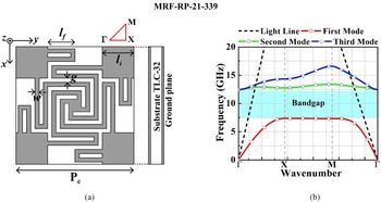
Figure 1(a) shows the layout of the proposed uniplanar EBG which consists of two metal layers separated by a dielectric substrate. The back metal layer acts as a complete perfect electric conductor (PEC) ground plane. The unit-cell geometry is printed on the front side of the substrate and has a 2D periodic configuration. The substrate material is Taconic TLC-32 (relative permittivity er = 3.2 and loss tangent tan δ = 0.003) having a thickness of 0.79 mm. The proposed unit cell consists of interdigital capacitors (IDC) along the outer edges and a four-arm spiral resonator at the center making it interconnected with corner square patches of length li. Fingers of the IDC are folded to adjust the overall capacitance of the structure. Each unit element is connected at the corners with adjacent unit cells. Hence in a full 2D array configuration, surface current in the spiral resonator flows from one unit cell to its adjacent ones and causes an increase in total inductance. The periodicity (Pc) of the proposed EBG is 4.2 mm or 0.13 λ 0, where λ 0 is free space wavelength at the center frequency of the bandgap. The final dimensions of the unit cell are lf = 0. 98 mm, li = 1.12 mm, w = 0.15 mm, g = 0.15 mm.
(a) Geometry of the proposed uniplanar EBG – front and side views; (b) simulated dispersion diagram.

Dispersion characteristics
EBG is generally characterized by its dispersion diagram which is a graphical representation of phase constant (β) and the wavenumber (k). For EBG, non-linear variation of β (or k) relative to frequency exists due to its lossy nature. EBG assists the propagation of different surface wave modes, each of them having a unique field configuration. The lowest propagation mode is transverse magnetic (TM) with zero cut-off frequency. Periodic geometry of EBG allows the existence of frequency bandgap between two modes. Within the bandgap, EBG suppresses the surface wave propagation. The proposed EBG is simulated in Eigen mode solver of high-frequency structure simulator (HFSS) by imposing periodic boundary conditions. Eigen mode frequencies are determined only over the Brillouin zone triangle consisting of Γ-X-M due to 90° rotational symmetry in the proposed geometry. The dispersion diagram of the proposed EBG is depicted in Fig. 1(b) and the result shows a bandgap from 7.37 to 12.4 GHz (50.9%) between the first two modes. The bandgap covers the entire X-band of the microwave spectrum.
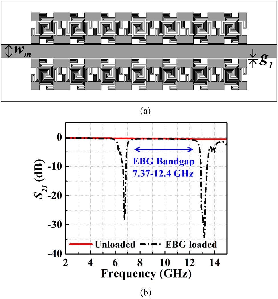
The aforementioned bandgap is further characterized by placing a seven-element 1D EBG array on both sides of a 50 Ω microstrip line as illustrated in Fig. 2(a). The spacing between the transmission line (TL) and the EBG array is 0.15 mm. Capacitive coupling between the proposed EBG and TL interacts with propagating transverse EM wave and opposes the propagation of the wave over specific frequency regions due to EBG's resonance nature. Figure 2(b) shows the transmission coefficient (S 21) of the EBG-loaded TL which exhibits two narrow stopbands at the center at 6.75 and 13.15 GHz. An increase in capacitance between the EBG and TL causes a shift of the first stopband frequency at a lower frequency range [Reference Kurra, Abegaonkar, Basu and Koul9]. The BW of two stopbands with S 21<−3 dB are over 6.21–6.97 GHz (11.53%) and from 12.76 to 14.1 GHz (9.98%).
(a) Schematic diagram of EBG coupled with microstrip line; (b) simulated transmission coefficients of EBG-unloaded and loaded transmission line. Design parameters are: wm = 1.9 mm and g1 = 0.15 mm.

EBG as frequency-selective surface
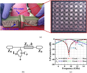
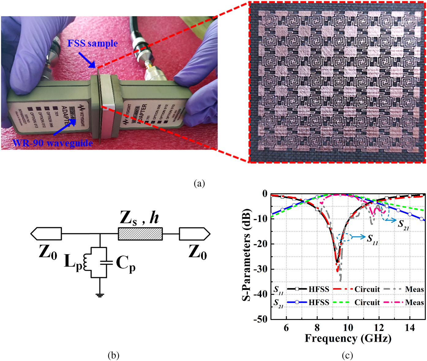
The reflection and transmission coefficients of the proposed EBG are determined for plane wave incidence. The back metal layer of the EBG is removed to allow transmission through the structure. Scattering parameters are obtained from full-wave numerical simulation under Floquet port excitation. The results are compared with the circuit simulation and the measured filter response is obtained using the waveguide measurement technique. Figure 3(a) exhibits the experimental setup for waveguide measurement with FSS placed inside the sample holder. EM wave impinges on the FSS from WR-90 waveguide with an operating range between 8.2 and 12.4 GHz. Two such waveguides act as the source and the receptor of the EM waves. The equivalent circuit of the proposed FSS is modeled as parallel resonant circuit Lp-C p as shown in Fig. 3(b). The effect of the dielectric substrate is taken into consideration by representing it as a short TL of characteristics impedance $Z_s = Z_0/\sqrt {\varepsilon _r}$ and the length h same as the substrate thickness. Here Z 0 is the wave impedance of free space having a value of 120 π or 377 Ω. While the surface current through the spiral resonator at the center contributes to total inductance (Lp), the fringing field between the fingers of IDC attributes to the capacitance (Cp). Numerical and circuit simulations of the proposed FSS are shown in Fig. 3(c) over the frequency sweep of 5–15 GHz. Final values of Lp and Cp are obtained using the curve fitting method in a circuit simulator and the values are 1.56 nH and 0.17 pF. The proposed FSS shows a simulated passband center at 9.32 GHz. The 3 dB transmission BW (S 21 > −3 dB) extends over 7.16–11.61 GHz (47.4%). Inside the X-band frequency range, measured scattering parameters are found consistent with the simulation results except for little discrepancies at the band edges. The discrepancy is caused by an increase in attenuation outside the operating range of the WR-90 waveguide.
(a) Waveguide measurement setup for the proposed EBG acting as FSS for plane wave incidence; (b) equivalent circuit model of the FSS; (c) simulated and measured reflection and transmission coefficients.
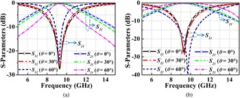
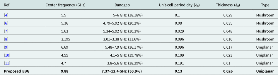
To illustrate the angular stability of the proposed FSS, the reflection and transmission coefficients of the FSS are simulated at different incidence angles. The simulated result in Fig. 4 exhibits a stable passband filter response of the FSS up to a high oblique incidence of 60° for both transverse electric (TE) and TM polarizations. The shifts in resonance frequency are <0.86% for TE mode and <4.5% for TM mode. The performance of the proposed EBG is compared with earlier reported unit cells in Table 1. Compared to unit cells in [Reference Venkata and Kumari4, Reference Yang, Fan, Chen, She and Feng6–Reference Abedin, Azad and Ali11], the proposed geometry achieves a higher bandgap with comparable unit-cell periodicity and thickness. Moreover relative to mushroom-type EBGs in [Reference Venkata and Kumari4, Reference Yang, Fan, Chen, She and Feng6–Reference Bhavarthe, Rathod and Reddy8], the proposed uniplanar configuration has an added advantage of less fabrication complexity due to the absence of metallic via.
Simulated reflection and transmission coefficients of the EBG acting as FSS for different incidence angles: (a) TE mode; (b) TM mode.

State-of-the-art performance comparison of the proposed uniplanar EBG with previously reported unit cells

Fabry–Perot cavity resonator antenna (FP-CRA)
The FSS characteristic of the proposed EBG is utilized in this paper to design a broadband high-gain CRA. The proposed EBG acts as a PRS superstrate over a broadband microstrip antenna. The primary feed antenna is a RIS-backed radiating patch which is characterized by wideband impedance matching, improved radiation performance, increase in FTBR, and reduced mutual coupling between the radiating patch and the ground plane.
RIS-backed broadband antenna
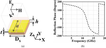
RIS exhibits in-phase reflection near its resonance for a plane wave incidence [Reference Meng, Liu and Sharma18]. Away from the resonance, the inductive reactance of RIS compensates for the capacitance associated with the electric energy stored in the antenna near-field region. This results in broadband impedance matching and miniaturization of radiating patch dimensions. In the present work, RIS consists of periodic square patches of array size 8 × 8 on a ground-backed TLC-32 substrate with a height of 0.79 mm. RIS unit cell has periodicity (Dx) 3.27 mm with a square patch length (a) of 2.87 mm. The copper with a thickness (t) of 0.035 mm is used as conducting material. The grounded dielectric substrate is modeled as short-circuited TL, which provides an equivalent inductance according to TL theory. The spacing between the adjacent square patches contributes to capacitance in parallel. The simulated reflection phase of the proposed RIS unit cell and its simulation setup for plane wave incidence are depicted in Fig. 5. The wave is incident along the Z-axis with the perfect magnetic conductor and PEC boundaries are assigned in the YZ and XZ planes, respectively. Figure 5(b) shows that the reflection phase varies from +180° to −180° and it decreases with the increase in frequency. The zero-crossing of the phase occurs at 11.8 GHz. The operating BW of the RIS is 10.36–12.92 GHz (22%) over which the reflection phase varies between +90° and −90°.
(a) RIS unit cell with simulation setup for plane wave incidence; (b) simulated reflection phase.

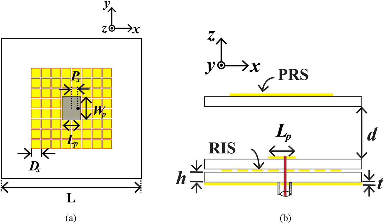
Figure 6(a) represents the layout of the rectangular patch antenna with the RIS-backed ground plane. Radiating patch has length (Lp) 5.8 mm, width (Wp) 7.6 mm, and it is printed on Taconic TLC-32 substrate with a height of 0.79 mm. The probe feeding is used to excite the antenna with the probe being located at a distance Px from the center along the x-axis. Simulation of the proposed patch antenna is performed in HFSS and the results are shown in Figs 7(a) and Figs 7(b). Antenna resonates at 11.1 GHz with a simulated impedance BW of S 11 < −10 dB from 10.31 to 12.76 GHz (21.24%) and having peak realized gain of 6.02 dBi.
(a) Schematic of the proposed broadband antenna on RIS; (b) side view of the proposed FP-CRA with EBG as PRS.

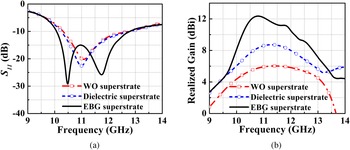
Simulated (a) reflection coefficient and (b) gain characteristics of the proposed broadband reference antenna and the EBG superstrate-loaded FP-CRA.

Antenna with EBG superstrate
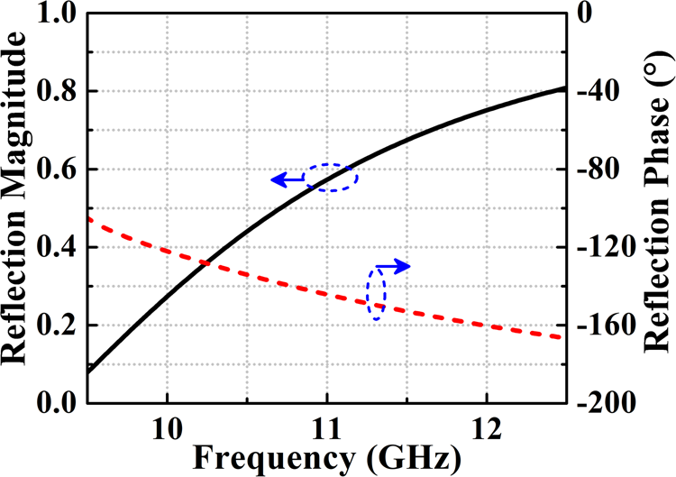
Low directivity of the proposed RIS-backed patch antenna is enhanced by placing an EBG superstrate over the radiator at a distance d from the patch surface as depicted in Fig. 6(b). The ground plane of the antenna and the superstrate layer form the two reflecting surfaces of the Fabry–Perot cavity inside which the radiating patch is placed as a primary feed. The EBG superstrate has the characteristic of PRS at the operating frequency of the antenna at which the magnitude of reflection coefficient is >0.55 and the reflection phase decreases linearly with frequency (see Fig. 8). Directivity of the primary antenna is enhanced due to multiple reflections of the radiating wave between the superstrate and the ground plane [Reference Foroozesh and Shafai13]. From the cavity, the wave is leaking out partially without any reflection while part of the wave is being transmitted after suffering reflection between the cavity walls. According to the principle of ray theory, two transmitted rays interfere constructively when the phase difference (Δϕ) between them is even multiple of 360° as obtained using (1) [Reference Foroozesh and Shafai13]

where N = 0, 1, 2, … (1)
Simulated reflection coefficient magnitude and phase variation of the proposed EBG superstrate.

Here ϕPRS is the reflection phase of the proposed EBG superstrate and “π” corresponds to change in phase after reflection from the PEC ground. Note that h′ is the total height of the superstrate from the ground plane and this can be rearranged according to (2)

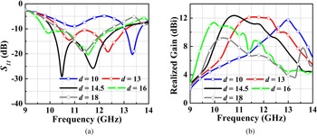
For the lowest order mode inside the cavity, N is equal to “0” and the height of the superstrate will be approximately λ/2 when the reflection phase of the superstrate is close to −180°. The gain and reflection coefficient of the proposed FP-CRA are illustrated in Fig. 7 along with the reference microstrip antenna. The performance of the proposed EBG as PRS is also compared with the dielectric superstrate-loaded RIS back antenna. Figure 7(b) shows the simulated peak realized gain of the combined antenna–superstrate structure reaches 12.35 dBi at 10.8 GHz with a gain improvement of 6.59 dB as compared with the reference antenna. Simulated impedance BW of the FPCA is 23.79% from 10.07 to 12.79 GHz and 3 dB gain BW is from 10.13 to 12.34 GHz (19.67%). The simulation result shows that composite antenna resonates at two frequencies center at 10.5 and 11.75 GHz. These two resonances correspond to radiating patch and the cavity resonance between the ground and PRS. EBG as PRS allows better impedance matching of the antenna over a wideband and a significant gain improvement as compared to dielectric superstrate. Sensitivities of the return loss and gain characteristics of the proposed FP-CRA are also observed by varying the superstrate height. Figures 9(a) and 9(b) present simulated S 11 and the gain of the proposed antenna for different air spacer heights (d). Impedance matching and gain of this FP-CRA significantly depend on the height of the PRS. Finally, the optimum height is determined to be 14.5 mm through parametric variation in HFSS.
Simulated (a) reflection coefficient and (b) gain variation of the proposed CRA at different air spacer heights.

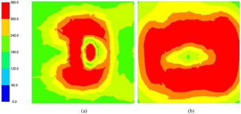
The improvement in gain due to superstrate loading can be explained by the electric field distribution over the radiating aperture of the FP-CRA. The unit cells of the EBG-superstrate behave as radiating elements due to partial reflecting characteristics and in effect increase the radiating aperture of the antenna. Figure 10 shows the magnitudes of the tangential electric field on a plane at a distance of 2 mm away from the radiating patch for the unloaded reference antenna and that on a plane at 2 mm away from the EBG superstrate for the proposed FP-CRA. For the reference antenna, a significant variation of electric field magnitude exists over the radiating aperture, which causes the low gain of the primary feed antenna. When the patch antenna is loaded with the superstrate, a uniform field distribution is achieved over a large area which increases the radiating aperture of the antenna. The enhancement in the effective radiating aperture of the antenna causes a higher gain of the CRA. The field magnitude on the radiating aperture of the cavity antenna follows a Gaussian distribution. For superstrate with the infinite lateral size, the directivity enhancement of the CRA is related to the reflection magnitude (ρ) of the PRS using (3) [Reference Wang, Liu, Wu, Talbi, Zeng and Xu28]

Magnitude of tangential electric field distribution on a plane for (a) unloaded reference patch; (b) EBG superstrate-loaded cavity resonator antenna at frequency 11 GHz.

Figure 8 shows that at the resonance frequency of the primary feed antenna, the designed PRS has ρ = 0.59 which gives the calculated value of Dr = 5.9 dB. Thereby total directivity of CRA is obtained as D = Dfeed + Dr. The directivity (Dfeed) of the reference patch antenna is 7.7 dBi at the resonance and results in total directivity of the CRA as D = 13.6 dBi. Assuming 80% efficiency of the antenna, the aperture area (A) of the superstrate is determined using (4) [Reference Wang, Liu, Wu, Talbi, Zeng and Xu28]

Here λ is the wavelength at the operating frequency. The lateral size of the CRA is found as 1.7 × 1.7 λ 2 for the required directivity of 13.6 dBi. The calculated radiating aperture size of the antenna closely matches with the actual aperture dimension of 45 × 45 mm2 consisting of 49 FSS unit cells.
Experimental results
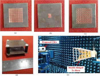
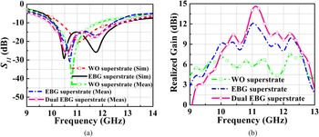
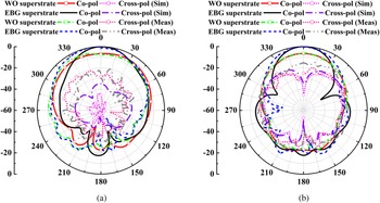
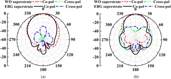
Figure 11 shows the photograph of the fabricated EBG superstrate-loaded CRA and the experimental setup inside an anechoic chamber to measure the radiation characteristics of the antenna. Four hexagonal nylon screws with a diameter of 5.8 mm are used to fix the superstrate layer at a height of 14.5 mm over the RIS-backed antenna. Measured reflection coefficients of without and with superstrate-loaded antenna are depicted in Fig. 12(a). In the absence of superstrate, antenna resonates at 10.79 GHz with 10 dB impedance BW of 10.26% (10.06–11.84 GHz). Measured S 11 < −10 dB of the proposed FP-CRA with a single layer of EBG superstrate extends over 10.02–12.43 GHz (21.5%). The gain variation of the proposed antenna is shown in Fig. 12(b). Within the return loss BW, the peak gain of the RIS-backed primary feed antenna is 6.52 dBi at 10.8 GHz. After EBG superstrate, loading peak gain is increased to 12.05 dBi with an improvement of 5.53 dB. The gain of the proposed antenna is further improved by using dual EBG superstrate layers. In measurement, spacing between the two EBG layers is optimized for maximum peak gain and the optimum value is obtained as 10.5 mm. Dual EBG superstrates stacking over the patch create two resonant cavities and cause an increase in BW. The measured impedance BW of the proposed dual EBG stacking FP-CRA is 9.91–12.71 GHz (24.8%) and having a peak gain of 14.3 dBi. The co-polarized and XPol radiation patterns of the proposed antenna are measured at the frequency 10.8 GHz. Figure 13 presents simulated and measured radiation patterns of the antenna in two principal planes (E and H) and both results are in good agreement with each other. A little discrepancy between simulated and measured patterns is noticed which can be attributed to the effects of the SMA connector and nylon spacer. Also, radiation losses from the cables bending and the variation in superstrate height can cause a mismatch in the patterns. The pattern shows a good co to XPol discrimination in both principal planes. Despite the measured XPol being a little higher as compared to simulated radiation patterns, the XPol is <−20 dB in E-plane and it is <−15 dB in H-plane. Patterns in both planes exhibit an increase in the directivity of the proposed CRA relative to the primary RIS-backed patch antenna.
Fabricated prototype of the proposed CRA (a) RIS; (b) rectangular patch; (c) EBG superstrate; (d) composite superstrate loaded antenna; (e) measurement setup inside the anechoic chamber.

Proposed CRA without and with superstrate loading: (a) simulated and measured reflection coefficient; (b) measured gain variation.

Simulated and measured radiation patterns of the proposed CRA without and with superstrate loaded: (a) E-plane (φ = 0°); and (b) H-plane (φ = 90°).

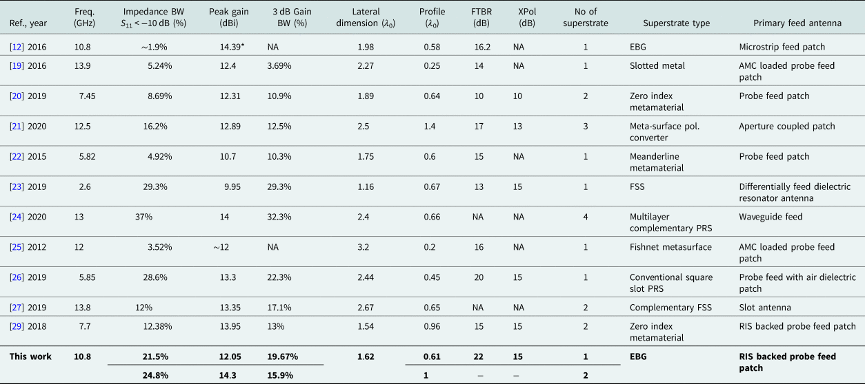
Table 2 presents the performance comparison of the proposed FP-CRA with the previous works. The proposed antenna possesses higher BW as compared to [Reference Kurra, Abegaonkar, Basu and Koul12, Reference Liu, Cao and Wu19–Reference Razi, Rezaei and Valizade22, Reference Li, Lei and Liang25, Reference Meriche, Attia, Messai, Mitu and Denidni27, Reference Majumder, Kandasamy and Ray29]. The gain of the proposed CRA is more as compared to [Reference Gupta and Parihar23] and for the remaining works, the gain is comparable. The work in [Reference Niaz, Yin, Bhatti, Cai and Chen24] has obtained higher BW and gain than the present work, but as a primary feed antenna open-ended waveguide is used in [Reference Niaz, Yin, Bhatti, Cai and Chen24], which is bulky and increases the cost of the structure. The proposed work possesses the advantage of the miniaturized lateral dimension of only 1.62 λ 0 with a simple BW enhancement method of FP-CRA without any considerable compromise on the peak gain.
State-of-the-art performance comparison of the proposed broadband FP-CRA with previous works

*Signifies simulated directivity.
Antenna array with EBG superstrate
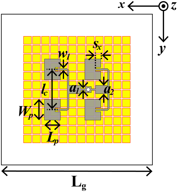
A 2 × 2 antenna array is printed over RIS-backed dielectric substrate as shown in Fig. 14. Here 12 × 12 RIS elements are used to cover the entire radiating aperture of the array. Each radiating patch of the array is uniformly excited using a microstrip line-based corporate feed network. Overall ground plane size of the array is 55 mm × 55 mm with patch dimension keeping same as those mentioned in the previous section. Center to center spacing between the array elements is 14.7 mm (0.525 λ 0 at 10.8 GHz) along both x and y axes. Figure 15 describes the simulated reflection coefficient and gain characteristics of this array without and with superstrate loading. For RIS-backed antenna array, the impedance BW for S 11 < −10 dB extends from 10.13 to 11.81 GHz (15.3%). The peak gain of the proposed array without EBG superstrate is 11.7 dBi and it poses the advantage of gain variation <1.4 dB over the operating range. Further improvement in gain is obtained by placing an 8 × 8 EBG superstrate over the array elements at a distance of 14.5 mm from the patch surface. The proposed array fed FP-CRA shows reflection coefficient BW over 10.01–11.42 GHz (13.16%). Peak realized gain of the proposed CRA array is 13.45 dBi with the maximum gain variation over the operating frequency range being only 1.21 dB. The E- and H-plane radiation patterns of the antenna array without and with superstrate are shown in Fig. 16 at frequency 10.5 GHz. After loading the superstrate over the antenna array, the co-pol to XPol discrimination reduces due to scattering of the wave from the edges of PRS, still the XPol is <28 dB for both planes. The proposed array also exhibits a low SLL of 22.57 dB with 3 dB beamwidths in two principal planes are 38.4° and 33.7° respectively. FTBR of the proposed antenna array is 26.3 dB at 10.5 GHz. The gain of the proposed array can be further improved by increasing the superstrate lateral size >2.5 λ 0 or using multi stacking technique.
Geometry of the 2 × 2 antenna array on the RIS. Design parameters are: Lg = 55, Lp = 5.8, Wp = 7.6, a 1 = 0.6, a 2 = 3, w 1 = 0.6, lc = 14.7, Sx = 1.95. All units are in mm.

Simulated (a) reflection coefficient and (b) gain variation of the proposed RIS-backed 2 × 2 antenna array without and with EBG superstrate loaded.

Simulated radiation patterns of the proposed RIS-backed 2 × 2 antenna array without and with EBG superstrate loading: (a) E-plane; (b) H-plane.

Conclusion
A novel uniplanar EBG unit is proposed in this paper having surface wave suppressing bandgap between 7.37 and 12.4 GHz (50.9%) which covers the entire X-band in the microwave spectrum. FSS characteristic of the proposed EBG is analyzed in detail by using it as a superstrate over a RIS-backed broadband patch antenna. RIS is used as an artificial ground for the patch to obtain impedance matching over a wide frequency range of operation. Measured results show that the proposed CRA has impedance BW of more than 20% with peak gain higher than 12 dBi. A flat gain over the operating BW is achieved by using a 2 × 2 antenna array as a primary feed of the proposed CRA. The gain variation below 1.21 dB with a maximum gain of 13.45 dBi has been obtained. The proposed broadband CRA has potential application for X-band radar and tracking systems. In future work, the proposed EBG will also be used as a decoupling network to improve the isolation between the antenna array.
Acknowledgement
The authors would like to express their profound gratitude to the Director of the Indian Institute of Technology Palakkad for setting up Central Instrumentational Facilities. This work is supported by the Science and Engineering Research Board, Government of India under project no: ECR/2018/002258. One of the authors thanks the support received from the Department of Science and Technology (DST), Government of India.
 Soumik Dey (student member, IEEE) graduated in physics (Hons.) from Ramakrishna Mission Residential College, Narendrapur in 2012. He received B.Tech. and M.Tech. in radio physics and electronics from the University of Calcutta in 2016 and 2018, respectively. He is currently pursuing a Ph.D. degree at the Department of Electrical Engineering, Indian Institute of Technology Palakkad, India. From December 2018 to June 2019, he worked as a research staff at IIT Palakkad where he joined the Ph.D. program in July 2019. He has published more than 10 research papers and filed two patents. His current research interest includes frequency selective surface, electromagnetic bandgap structure, multiband and broadband microstrip antenna, and substrate integrated waveguide. He is also a recipient of the DST Inspire Fellowship from the Government of India.
 Sukomal Dey (senior member, IEEE) received B.Tech degree in electronics and communication engineering at the West Bengal University of Technology, Kolkata, India, in 2006, an M.Tech in mechatronics engineering at the Indian Institute of Engineering Science and Technology (IIEST), Shibpur, India, and obtained an M.Tech in one year from the Central Electronics Engineering Research Institute (CEERI-CSIR), Pilani, India, in 2009. Dr. Dey obtained a Ph.D. from the Centre for Applied Research in Electronics (CARE), Indian Institute of Technology Delhi in July 2015. From August 2015 to July 2016 he was working as a project scientist in the Industrial Research and Development (IRD) centre, IIT Delhi. He also worked on a collaborative research project supported by Synergy Microwave Corp., NJ, USA during the same period. From August 2016 to June 2018, he was working in the Radio Frequency Microsystem Lab (RFML), National Tsing Hua University, Taiwan, as a postdoctorate research fellow. Since June 2018 he is working as an assistant professor at the Department of Electrical Engineering, Indian Institute of Technology Palakkad, Kerala.
Dr. Dey is a recipient of the Postgraduate Student Award from the Institute of Smart Structure and System, Bangalore, in 2012, Best Industry Relevant Ph.D. Thesis Award from the Foundation for Innovation in Technology Transfer, IIT Delhi in 2016, Postdoctoral Fellow Scholarships from the Ministry of Science and Technology (MOST), Taiwan in 2016 and 2017, respectively, Early Career Research Award (ECRA) from the Science and Engineering Research Board (SERB), Government of India in 2019 and Smt. Ranjana Pal Memorial Award (2021) from the Institution of Electronics and Communication Engineers (IETE). He has authored/co-authored more than 70 research papers, one state-of-the art book, and two book chapters. Dr. Dey holds three and filed six patents. His research interests include: RF MEMS, microwave, to sub-mm wave metamaterial structures and microwave integrated circuits including antennas.