I. BACKGROUND AND INTRODUCTION
The deformation field obtained in metal indentation has been the subject of numerous investigations, both theoretical and experimental, due largely to its relevance for studying elastic and plastic properties of solids.Reference Oliver and Pharr1–Reference Tabor4 In this context, hardness numbers and force–displacement curves obtained from instrumented indentation may be considered to provide a global picture of the indentation process. While such information is adequate for engineering purposes, the integrated nature of these quantities means that they do not reveal sufficient information about the underlying details of plastic flow, kinematics of material displacement, and self-similarity of deformation.
Early work to study deformation in wedge indentation directly was carried out by Hill et alReference Hill, Lee and Tupper5 using slip-line field theory to analyze frictionless wedge indentation. The analysis provided a characterization of the mean contact pressure in terms of yield strength and indenter angle. In the same work, the deformation was studied using split lead specimens. A grid was inscribed on one-half of the lead specimen, and the two halves were held together during indentation. The postindentation deformation pattern was examined after separating the two halves to assess the nature of the deformation. MulhearnReference Mulhearn6 investigated the deformation pattern produced by indentation of cold-rolled steel using wedges of different apical angles and showed that the deformation pattern changes from “cutting” to “radial compression” as the apical angle is increased. Hirst and HowseReference Hirst and Howse7 subsequently demonstrated that the elasticity of the indented metal and its yield point affects the deformation pattern. Other investigations showedReference Haddow8 (also see Ref. Reference Johnson9) that the friction coefficient influences the deformation pattern considerably, with “compression” type deformation promoted by high friction and “cutting” type deformation by low friction. Besides grid deformation, metallographic etching methods have been used to identify elastic–plastic and low strain boundaries in spherical indentation of metals such as 70:30 brass.Reference Samuels and Mulhearn10 Deformation studies have also been conducted with other indenter geometries such as cones.Reference Atkins and Tabor11
In contrast to an externally imposed grid, ChaudhriReference Chaudhri12, Reference Chaudhri13 used microstructural features present in the material as intrinsic grid markers to measure deformation in spherical indentation. Specifically, pearlite “stringers” (lines) in drawn mild steel served as the intrinsic markers. The indentation was carried out so that the axis of loading was perpendicular to the direction of the pearlite stringers, and the strains were estimated from the displacements produced. The method cannot, however, provide deformation rate measurements and is not suited for metals that lack internal microstructural features as markers.
More recently, the latter limitations have been surmounted by the application of particle image velocimetry (PIV), an image correlation technique, to characterize deformation directly during indentation.Reference Lee, Hwang, Shankar, Chandrasekar and Compton14 In this approach, markers are introduced on to a side of the specimen by use of abrasion or sand blasting methods and the displacement field is then obtained by analysis of the motion of these markers during indentation. In particular, PIV allows for determination of strain rates, plastic strain, displacement, and velocity fields in the vicinity of an indentation at high spatial resolution. The method has been successfully applied to study plane-strain indentation of metals by a flat punchReference Murthy, Huang and Chandrasekar15, Reference Murthy, Madariaga and Chandrasekar16 and is used to study wedge indentation in this study.
Along with better characterization techniques, computational hardware and software have improved to the extent that indentation, at least in plane strain, may be simulated using finite element analysis (FEA) without the use of specialized high performance computing systems or loss of spatial/temporal resolution. Thus, it is possible to obtain high fidelity solutions without any of the restrictive assumptions of slip-line plasticity theory. FEA studies have been used to simulate axisymmetric indentation of metals by spheresReference Follansbee and Sinclair17 and conesReference Mata, Anglada and Alcala18; a comprehensive list of indentation FEA studies is given in a recent article by Jiang et al.Reference Jiang, Sinclair and Meng19
FEA complements the PIV (experiment) in several important ways. First, it allows a degree of parametric flexibility that is tedious to achieve in indentation experiments. Second, it allows for a systematic exploration of frictional effects at the specimen–indenter interface, which is experimentally difficult. This is especially important considering the influence of friction on the deformation pattern. Third, FEA helps enhance the efficacy of PIV by revealing likely regions of interest from the perspective of deformation as well as novel ways to query experimental results. However, this assessment of the deformation using FEA is of value only if the computed deformation field shows good qualitative agreement with experimental results. This aspect is taken up in this study in the framework of wedge indentation. The combination of PIV and high fidelity FEA, as will be seen, allows for characterization of the deformation field with unprecedented level of detail.
The primary focus of this study is on the rotation field associated with the deformation under a wedge indentation. Earlier investigations of plane-strain punch indentation using PIV calculated such measures of deformation as strain, strain rate, and velocity,Reference Murthy, Huang and Chandrasekar15, Reference Murthy, Madariaga and Chandrasekar16 but the rotation field underlying an indentation has not been examined so far. In this work, the rotation field is computed, and the information it contains about indentation has been examined. Since the rotation field is a scalar field with an intuitive geometric interpretation, it will be seen that it provides a convenient framework to highlight important aspects of the deformation process.
The results presented in this work are part of an ongoing study of wedge indentation of metals using PIV, complemented by FEM analyses. The overarching goals are to understand the kinematics of deformation and the correlation of indentation/material parameters with characteristic structures formed during deformation. An additional objective is the development of novel methods to query the (very large) data sets resulting from PIV and FEA so as to facilitate better understanding of the deformation process, and rotation field visualization is one such method.
II. EXPERIMENTAL DETAILS
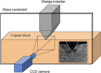
Plane-strain indentation was performed on annealed OFHC copper specimens, 5 in. long × 1 in. wide × 1 in. high (127 mm long × 25.4 mm wide × 25.4 mm high), using wedge indenters of apical angles of 60° and 120°. The wedges were made of high-speed steel, with the faces of the indenter finish machined by grinding. The indentation was carried out on an MTS Qtest/50LP tension/compression test machine, in which the indenter was kept stationary and attached to the upper crosshead, while the copper specimen was moved by the lower crosshead at a speed of 0.04 in./s (1 mm/s) toward the indenter (Fig. 1). During the indentation, one side of the copper specimen, (127 × 25.4 mm) which is parallel to the plane of the material flow, was imaged at a frame rate of 30 fps using a CCD camera (PCO 1600, Cooke Corp., Romulus, MI) coupled with an optical microscope assembly. The resulting image with 1600 × 1200 pixels captured a physical area of 0.44 × 0.33 in. (11.2 × 8.4 mm) around the indenter. The spatial resolution of this arrangement was 0.00028 in. per pixel (0.007 mm per pixel). The material flow during the indentation was recorded in a sequence of images. By analyzing pairs of consecutive images along the sequence using image correlation, i.e., PIV, the incremental displacement or velocity vector field corresponding to each time interval (1/30 s) was obtained. Deformation parameters including strain, strain rate, and rotation may then be derived from the measured displacement/velocity vector fields.
Schematic of the experimental arrangement used to study wedge indentation.

Schematic details of the experimental arrangement for assessing deformation using the PIV setup are shown in Fig. 1. A transparent glass block is used to restrict out-of-plane flow and simulate plane-strain conditions. Apart from the specimen and indenter, the PIV setup, calibration method, and image processing algorithms are similar to those used in earlier work.Reference Murthy, Huang and Chandrasekar15 The inset in Fig. 1 shows a typical image frame recorded during indentation.
III. FINITE ELEMENT SIMULATION
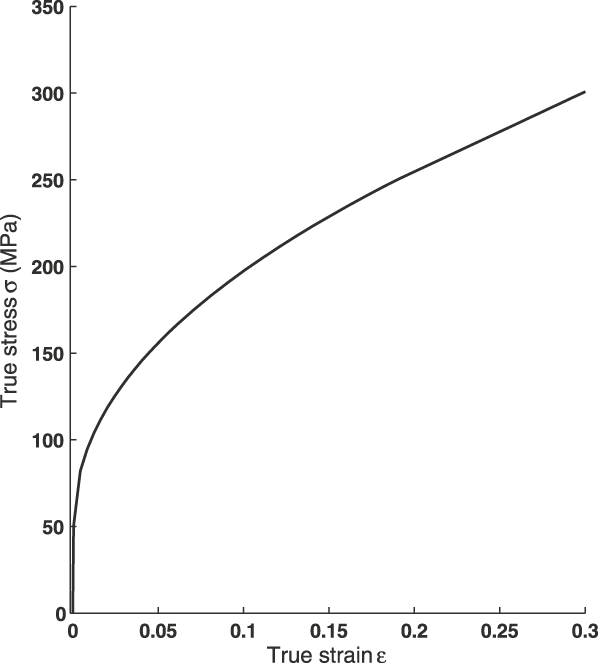
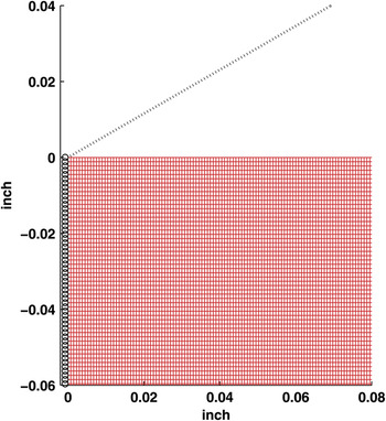
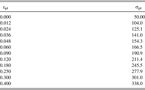
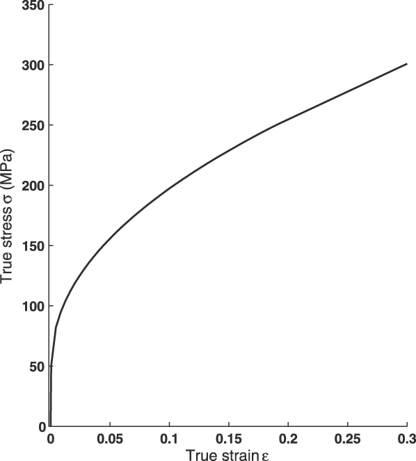
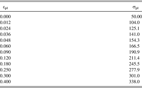
The ABAQUS/STANDARD FEA software was used to simulate the indentation process, mainly because of its excellent contact analysis capability. The indenter was modeled as a discrete rigid body, while the annealed copper specimen was modeled as a rate-independent, elastic–plastic material with isotropic hardening (see Fig. 2 and Table I). Four-node, initially rectangular, plane-strain elements with full or reduced integration were used in the specimen for indentation by the 120° wedge. To avoid excessive element distortion in case of indentation by a 60° wedge, high aspect ratio (3–3.5) rectangular elements were used. The meshes were made and optimized using a custom mesh generator for contact and indentation analyses. A close-up of one of the meshes used for the 120° wedge indentation is shown in Fig. 3. The specimen and indenter were modeled using half-symmetry to save analysis time.
Stress–strain curve for the annealed copper. The Young’s modulus E = 112 GPa.
A close-up view of the finite element analysis (FEA) mesh used to simulate the 120° wedge indentation. The circles indicate the use of symmetry boundary conditions. The wedge indenter is modeled using discrete rigid elements.

Annealed copper plastic strain–plastic stress (MPa) data used in finite element analysis simulations.
Note, however, that the matter also involves separating a fictitious “elastic” contribution to the rotation.Reference Lubliner20
The indentation was simulated using displacement control by imparting a small downward velocity of 0.01 in./s (0.254 mm/s) to the indenter while holding the specimen fixed. This loading rate is small enough that the kinetic energy of the specimen is negligible compared to plastic dissipation. It may be noted that the smallest dimension of the specimen mesh was chosen to be at least 50 times the indentation depth of 0.05 in. (1.27 mm) to avoid edge or thickness effects and effectively simulate a semi-infinite specimen.
To integrate the plastic field accurately, a maximum time increment of 0.005 s was used, leading to the simulation of 5 s of indentation in 1100–1400 increments (including cutbacks by the solver). The mesh size in the region immediately beneath the indenter was chosen to have between 80 and 120 specimen elements in contact with the wedge, leading to element widths between 0.00025 in. (6 μm) and 0.00075 in. (19 μm). The wedge-specimen contact was modeled using a Coulomb friction coefficient (μ) of 0.5 to better replicate the effects of the unlubricated wedge used in the experiment. The FEA simulations used a node-to-surface contact pair algorithm, with contact boundary conditions enforced using Lagrange multipliers. Additionally, low friction cases were studied using friction coefficients of 0 and 0.1. After each analysis, the results were checked for hourglassing (with reduced integration) or mesh locking (for fully integrated elements). When full integration was used, the pressure tractions were extracted and examined to make sure that pressure spikes, usually indicative of excessive local stiffness or distortion, did not occur. Postprocessing of the FEA results, described in detail in the next section, then allowed for computation of rotations and strains. The FEA results were examined in comparison with the PIV measurements to assess the quality of the simulation predictions. It was verified that the spatial and temporal discretization used are adequate to obtain rotation field convergence (see next section); the maximum angle of rotation was used as the convergence parameter.
IV. CALCULATION OF ROTATION AND STRAIN FIELDS
Somewhat different considerations apply for calculation of plastic strain and rotation since the former is treated incrementally in a plasticity model. On the other hand, a measure of rotation that is easy to interpret geometrically is better defined in an absolute way. Details of the definitions and calculations presented here may be found in texts on continuum mechanics and plasticity.Reference Lubliner20, Reference Bower21
The basis for calculation of the rotation field is the principle of locally homogeneous deformation of continuum mechanics. This assumes that the deformation of an infinitesimally small element of the material can be represented using a combination of stretches, shears, and rotations. In FEA, using 4-node bilinear elements, initially rectangular elements deform into quadrilaterals. If the elements are sufficiently small, and deformation calculations performed separately at each node of the element, the displacement gradient inside an element due to bilinear interpolation may be ignored without loss of accuracy and the deformation treated as locally homogeneous. Similarly, in PIV, the use of a sufficiently fine grid results in deformed elements whose sides are negligibly curved, i.e., approximately quadrilaterals, with very little variation of strain across the element. The fineness of the grid is limited only by the PIV spatial resolution.
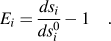
Consider two perpendicular sides of an initially rectangular element meeting at a node. The sides are aligned with the global axes in the undeformed state. Let the initial lengths of the two sides be ds 10 and ds 20, and the final lengths, respectively, ds 1 and ds 2. Then, the extensions Ei, i = 1,2 are given by
If ϕ 1 and ϕ 2 are the angles between the deformed and undeformed line elements, respectively, the deformation gradient is given by

It is well knownReference Bower21 that the deformation gradient may be reduced by polar decomposition into a pair of matrices V and R. First, the left Cauchy–Green tensor is computed from F as

The eigenvalues of C are the squares of the principal stretches, λ i2. Let the normalized eigenvectors of C be denoted as Wi. The symmetric left stretch tensor V is then found by taking the following dyadic (tensor) product

The rotation tensor, R, is finally given by

Since R is a rotation matrix, it may be expressed in terms of a scalar rotation angle, θ
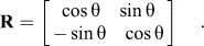
This scalar, θ, is used in the ensuing discussion to characterize the rotation. Note that since the global coordinates of all nodes in the deformed state are obtained as outputs from FEA, the final lengths ds 1 and ds 2 are easily calculated. Similarly, the displacement of an initially undeformed grid is tracked using PIV in the experiments and the final position of each node used to compute ds 1 and ds 2. With these values known, Eqs. (1)–(6) can be used to obtain the scalar rotation θ at a single node. Repeating these calculations for all nodes in the deformed grid provides the scalar rotation field. The interpretation of the tensor R, and the choice of θ to measure rotation over alternatives, is discussed in a subsequent section.
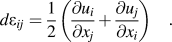
The calculation of plastic strain uses a somewhat different technique. This is because unlike rotation, which is defined in terms of the initial and final configurations above, a meaningful measure of plastic strain must depend on the history of deformation of each element and not merely on their initial and final shapes. In the PIV assessment, the observed deformation history is divided into small increments, and each individual increment is considered using small deformation measures. Given the incremental displacement vector field u i, the incremental strain tensor may be written asReference Thomsen, Yang and Kobayashi22
The effective strain increment is obtained using the von Mises yield criterion as
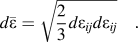
The total equivalent strain is then found by integrating these increments over the deformation history

In the simulations, the equivalent plastic strain field is returned as an output by the ABAQUS FEA solver and need not be computed separately. For a discussion on the validity of summing effective plastic increments, see Hill.Reference Hill23
V. RESULTS AND DISCUSSION
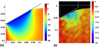
Contours of the rotation field obtained using FEA (simulation, friction coefficient μ = 0.5) and PIV (experiment) for indentation of annealed Cu by a 120° wedge are shown in Figs. 4(a) and 4(b) respectively. All angles are in degrees, with clockwise rotations considered positive.
Calculated rotation field (θ°) for indentation of annealed Cu by a 120° wedge using (a) FEA and (b) particle image velocimetry (PIV). Depth of indenter penetration is 0.05 in. (1.27 mm) and the field corresponds to that under load. μ = 0.5 for FEA.

The figures show good qualitative agreement between the FEA and PIV rotation fields. As expected, the rotation angle is almost zero along the symmetry line. In both cases, the largest rotation angles (30° in FEA and 20° in PIV) occur close to the wedge/specimen interface. The FEA angles are somewhat higher than the PIV values because PIV measurements close to the interface are difficult to perform accurately and because the spatial resolution of the FEA is higher. Notably, the rotation field is almost entirely unidirectional (negative/counterclockwise) in the imaged region. The free surface shows a “sink-in” pattern as expected for indentation of an annealed metal.
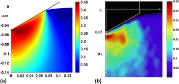
The equivalent plastic strains for the 120° wedge indentation obtained from FEA and PIV are shown in Figs. 5(a) and 5(b), respectively. The magnitudes of the peak strain (0.45 in FEA and 0.42 in PIV) and the locations of these peaks are seen to match fairly well. Likewise, there is good agreement in the overall pattern of deformation. In both cases, the peak strain is close to the tip of the wedge and along the line of symmetry. However, the decrease in strain values near the interface observed using PIV is appreciably greater than those in FEA due possibly to the reduced accuracy of PIV in that region.
Calculated equivalent plastic strain field for indentation of annealed Cu by a 120° wedge using (a) FEA and (b) PIV. Depth of indenter penetration is 0.05 in. (1.27 mm) and the field corresponds to that under load. μ = 0.5 for FEA.

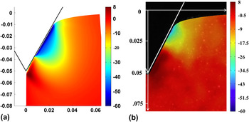
The rotation fields for indentation by a 60° wedge are shown in Fig. 6. On comparing the FEA and PIV rotation fields, it is clear that the zones of highest rotation angles are concentrated in a region close to the interface and near the center of the wedge face. Again, there is good agreement between the rotation field in FEA and PIV except for a thin layer along the interface.
Calculated rotation field (θ°) for indentation of annealed Cu by a 60° wedge using (a) FEA and (b) PIV. Depth of indenter penetration is 0.05 in. (1.27 mm) and the field corresponds to that under load. μ = 0.5 for FEA.

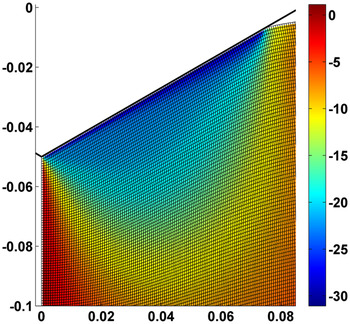
A comparison of the 60° and 120° rotation fields shows interesting contrasts that illustrate the difference in deformation modes. The rotation field has a steep gradient close to the tip of the 60° wedge [Figs. 6(a) and 6(b)] and decreases quickly to zero in either direction away from the tip, indicating that the deformation field is more localized. Furthermore, there is a small region of contrary (clockwise) rotation close to the 60° wedge tip in both FEA and PIV rotation fields. This indicates the more severe nature of deformation in the 60° indentation, with interface elements closer to the wedge face rotating in a direction opposite to those elements further away from the tip. The zone of clockwise rotation close to the tip is not a consequence of tip blunting in the experiments because it is also observed with FEA, wherein the wedge is taken to be perfectly sharp. When the deformed mesh is overlaid on to the rotation field for the 120° wedge indentation (Fig. 7), it is clear that the deformation mode is of “compression” type. An examination of the superposed deformed grid also provides rough visual confirmation of the accuracy of the calculated rotation field. Overall, the generally good agreement between FEA and PIV provides encouragement in using the FEA results.
Postindentation mesh overlaid on the rotation field for indentation of annealed Cu (120° wedge, μ = 0.5).

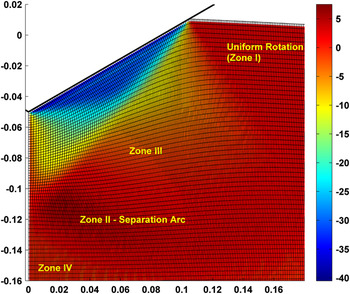
Figure 8 shows the rotation field produced in indentation of strain-hardened Cu, modeled as an elastic-weakly hardening plastic solid using FEA (with first yield at 145 MPa). In this instance, as expected, the free-surface exhibits “pile-up,” with material displaced above the horizontal. Interestingly, the nearly uniform, small-angle (about 5°) rotation in a triangular region (labeled “Zone I”) roughly corresponding to the pile-up zone suggests that the material in this region moves largely as a single block. Figure 8 also shows an arc-shaped zone (“Zone II”) separating the region of higher rotation (“Zone III”) from one of nearly zero rotation (“Zone IV”); the overlaid mesh indicates that this also corresponds closely to the separation between regions of low and high deformation. Such a separation zone is assumed to exist, e.g., in slip-line field analysis of indentation of work-hardened metals.Reference Hill, Lee and Tupper5
Postindentation mesh overlaid on the rotation field for indentation of work-hardened Cu (120° wedge, μ = 0.5).

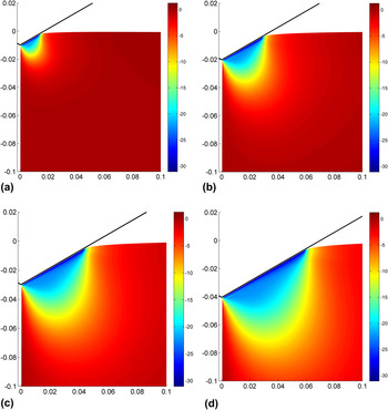
FEA may also be used to study the evolution of the rotation during indentation. Figure 9 shows an example of such an evolution during indentation of annealed Cu by a 120° wedge. The rotations are calculated at 20, 40, 60, and 80% of the total indentation depth. The rotation field is seen to be fully developed even at 20% of the indentation. The field subsequently increases only in size, revealing that the rotation field evolves in a geometrically self-similar manner, at least when a “compression” type deformation pattern is involved.
Evolution of rotation field in FEA simulation of indentation of annealed Cu by a 120° wedge at (a) 20, (b) 40, (c) 60, and (d) 80% of the final indentation depth of 0.05 in. (1.27 mm). μ = 0.5.

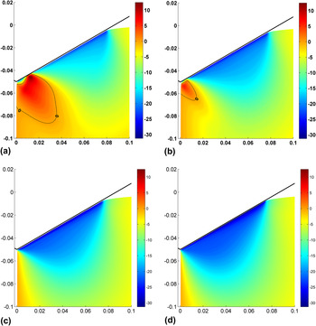
It is known that as the friction is increased, the deformation mode in indentation transitions from “cutting” to “compression” with low values of μ favoring cutting and high values of μ favoring compression. Figure 10 shows the rotation fields obtained in indentation of annealed copper by a 120° wedge using friction coefficients μ of 0, 0.1, 0.25, and 0.5. The rotation field provides for a clear distinction between the “cutting” and “compression” type deformation and captures this transition. The rotation field for higher friction cases is unidirectional [Figs. 10(c) and 10(d)], but the field in low friction cases [Figs. 10(a) and 10(b)] consists of closely spaced regions of clockwise and counterclockwise rotation near the tip. The high rotation gradients near the 0° contour indicate a zone of high shear caused by the tendency of elements on either side of it to rotate in opposite directions. Based on these observations, it is possible to define the “compression” mode as one in which the rotation field is unidirectional on one side of the symmetry line. Similarly, the “cutting” mode may be defined as the mode in which the rotation field is bidirectional on one side of the symmetry line. Note that the transition from “cutting” to “compression” is largely complete at μ = 0.25.
Dependence of rotation field on friction coefficient in indentation of annealed copper by a 120° wedge. The friction is (a) μ = 0.0 (b) μ = 0.1 (c) μ = 0.25, and (d) μ =0.5. A change in the deformation pattern from compression (c, d) to cutting (a, b) with decreasing friction coefficient is seen to be reflected in the rotation field. In cutting type deformation (a, b), a zero contour separating regions with elements rotating in opposite directions is present.

It is interesting to draw an analogy between the transition from “compression” to “cutting” mode in indentation with the “laminar” to “rotational” transition in rotational plasticity in a different context.Reference Brown24 Although the present work considers material behavior lying entirely within the realm of continuum solid mechanics, the steep rotation gradients and opposing angular motion in “cutting” indicate a greater propensity for circulation (rotational flow) than the low gradients and unidirectional rotation in “compression” (laminar).
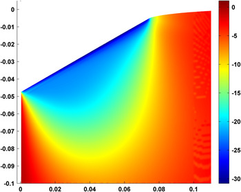
Finally, the rotation field as defined and used in this work has a particular interpretation that is useful to elaborate. In continuum mechanics, the rotation tensor R represents the average rotation of all material fibers passing through a material point for a general (i.e., large) deformation,Reference Bower21 and it may be generated from a single scalar (angle) field with no loss of generality. Due to plasticity, this is not a local rigid-body rotation as it would be for purely elastic, large deformation. The rotation field thus carries information about plastic flow as well. Further evidence of this fact may be seen in the postunloading (residual) rotation field in Fig. 11. This residual rotation field is essentially the same as that at full load, as a comparison with Fig. 4(a) (the fully loaded case) reveals.
Residual rotation field after unloading. The field is essentially unchanged after removing the wedge. Annealed Cu indented by a 120° wedge, with μ = 0.5.

An alternative way to define rotations is to consider the differential rotation field at each increment of the deformation, which represents the change in average orientation of fibers passing through a material point in that increment and measure the true rigid body rotation at a particular increment of the plastic deformation.Reference Oliver and Pharr1 However, there is no unique method to generate an “equivalent” rotation over the history of deformation from this sequence of rotations. Further, the obvious choice of summing the angles of all such rotations (analogously, the product of all incremental rotation tensors) over the history of a material point into a single number is difficult to interpret geometrically.
The difficulty in interpreting an “equivalent” angle definition has an analogy with the fact that the integral of all plastic strain increments over time may be interpreted as a logarithmic (true) strain only if the principal axes do not rotate relative to the element during deformation. In other cases, the sum (or integral) may still be formed but, as described by Hill,Reference Hill23 its validity is justified only by experiments. Thus, the choice of a measure of rotation that is easily computed and corresponds roughly to observed rotation patterns is preferable and this is the route that has been taken in this work.
VI. CONCLUSIONS
The rotation field in wedge indentation of copper has been estimated from measurements of the deformation using PIV and from finite element simulation of the indentation. Good agreement is seen between the rotation derived from the measurements and that estimated using the simulations. The rotation field is shown to be of value in characterizing the principal features of the deformation. The rotation field allows a clear distinction to be made between cutting and compressive modes of deformation. Largely unidirectional rotation on one side of the symmetry line with low spatial gradients is characteristic of compression, while bidirectional rotation with neighboring regions of opposing rotations with high local gradients characterizes cutting mode deformation. The rotation field also demarcates such characteristic regions as the pile-up zone and zone of small deformation obtained in indentation of a strain-hardened metal. The residual rotation prevailing after unloading of the indenter is largely unchanged from that at full load. Taken together with the ability to identify characteristic indentation modes, this indicates that rotation is a suitable scalar proxy for plastic deformation as a whole. A characterization of the rotation field during the loading process suggests that it evolves in a self-similar manner in indentation of annealed copper.
ACKNOWLEDGMENT
This work was supported in part by the National Science Foundation Grant CMMI 0928337.