Nomenclature
- FFD
free-form deformation method
- NURBS
non-uniform rational b-splines
- BFFD
b-spline based free-form deformation
- NFFD
NURBS based free-form deformation
- p-BFFD
reverse solution points based BFFD
- CP-BFFD
control points of new distribution based BFFD
- EDGE-p-BFFD
edge constraints based p-BFFD
- L, M, N
control points number in the three perpendicular directions
- R
basic function in FFD
 ${\boldsymbol{P}_g}_{i,j,k}$
control points coordinates
- ${\boldsymbol{x}_g}$
coordinates of parameterised object
- g
global coordinates
- s,t,u
local coordinate of the control body
- X
global position vector of object point
- X 0
position vector of the origin of the local coordinate system relative to the origin of the
global coordinate system
- S,T,U
three axis directions of the local coordinate system
- B
Bernstein basis function
- B i,k(s)
B-spline basic function
- u s
nodes vector of the B-spline basis function
- N i,k(s)
NURBS basic function
- ${\omega _i}$
weight coefficient introduced into NURBS basic function
- k
the order of B-spline function
- $\varepsilon _x^2$, $\varepsilon _x^2$, $\varepsilon _x^2$
square of deviation value of average distance in the direction of the three axes of xyz
- n
the number of target object points
- ${x_i}\,{y_i}\,{z_i}$
coordinate values of the object points obtained by parameterised expression
- $x_i^*\,y_i^*\,z_i^*$
original coordinate value of the object points
- $\boldsymbol{x}_g^*$
global coordinates of the unknown configuration
- $\boldsymbol{P}_g^*$
global coordinates of the control points of the unknown configuration
- $\boldsymbol{x}_{\textrm{u}}\,\boldsymbol{y}_{\textrm{u}}\,\boldsymbol{z}_{\textrm{u}}$
point cloud coordinates of upper surfaces
- $\boldsymbol{x}_{\textrm{l}}\,\boldsymbol{y}_{\textrm{l}}\,\boldsymbol{z}_{\textrm{l}}$
point cloud coordinates of lower surfaces
- $\boldsymbol{z}_{\rm{u}}^*$
normalised local coordinates of the upper surface
- $\boldsymbol{z}_{\textrm{u,stead}}^*$
local coordinates after being translated to the top of the control body


1.0 Introduction
In recent years, the flight mode of boost gliding or cruising has gradually become a research hotspot by virtue of the advantages of long-range, fast terminal speed and strong penetration ability [Reference Wei and Wang1–Reference Gerdroodbary and Tajdaran5]. The lifting body has a better comprehensive performance of gliding and cruising by virtue of the structural design of wing-body fusion, so the optimisation of lift configuration is very important for the smooth implementation of glide patrol mission. The optimisation process of lifting body is relatively complex, and it is necessary to consider the cooperative influence of many disciplines, such as aerothermal, aerodynamic force, volume ratio and other factors, and the shape should be constantly changed to find the most suitable comprehensive performance. In this context, the development of a parametric method which can achieve efficient deformation of lifting body is very important to improve the efficiency of optimisation [Reference Leng, Shen and Zhang6].
Parameterisation method always plays an important role in aircraft conceptual analysis and experimental design. A good parameterisation method can realise the complete expression of the configuration with fewer parameters, and there is a lot of room for deformation design. According to the different application objects, parameterisation can be divided into two-dimensional and three-dimensional parameterisation methods.
Among the two-dimensional parameterisation methods, the common methods include B-spline method, [Reference Schoenberg7] Class/Shape function transformation method (CST), [Reference Kulfan8] Parametric Section (PARSEC) method [Reference Kontogiannis, Sóbester and Taylor9] and Hicks-Henne method [Reference Han and Zingg10]. With its strong local modification ability and flexible control characteristics, B-spline has become one of the most commonly used parameterisation methods, which is often integrated into other methods, and has been widely used in the field of commercial CAD software [Reference Zhang, Zhao and Gao11]. Han and Zingg [Reference Han and Zingg10] combined the classical B-spline formula with the node insertion algorithm, and proposed an adaptive geometric parameterisation method to represent the aerodynamic shape in the process of shape optimisation, and applied it to the examples of aerofoil optimisation and induced drag minimisation. The optimisation results show that this method is more effective than the uniform parameterisation method.
For the three-dimensional parameterisation method, it is relatively simple to use the two-dimensional method to express the three-dimensional configuration. For example, Zhang et al. [Reference Zhang, Fang and Chen12] used the two-dimensional CST method to design the aerofoil with root, kink and tip section, and used the lofting technique to generate a complete wing. Furthermore, the method is extended from two-dimensional to three-dimensional. Su et al. [Reference Su, Gu and Gong13] optimised the configuration of class X-33 based on three-dimensional CST method and hypersonic engineering estimation method. Straathof et al. [Reference Straathof, Carpentieri and Tooren14, Reference Straathof and Tooren15] combined B-spline with CST method, and proposed CSRT method, which was then extended to 3D design space and applied to aircraft wing design. At present, the most common three-dimensional parameterisation method is the free-form deformation method (FFD), which was proposed by Parry and Sederberg [Reference Sederberg and Parry16] in 1986. At first, it is to achieve a breakthrough in the field of animation, and then it has been widely used in geometric deformation and mesh adjustment.
The traditional FFD parameterisation method uses the Bernstein basic function. The uniformly distributed control points are generated in the box frame, and the deformation operation of the target object in the lattice is realised by adjusting the position of the endpoints. Xu et al. [Reference Xu17] applied the classical FFD method to the osculating cone waverider, controlled the shape of the waverider through uniformly distributed control points, and the aerodynamic performance was optimised by using Kriging surrogate model on the premise of meeting the constraints. Shen et al. [Reference Shen, Huang and Zhang18] expressed the configuration of European Expert reentry vehicle through FFD parameterisation method, realising flexible control of the configuration with less design variables, and the vehicle was applied to multidisciplinary design optimisation obtaining better optimisation results in limited optimisation time. Bernstein is the most basic and simplest basic function in FFD method, but it faces the problem of insufficient local control ability, that is, moving a control points will cause global changes. B-spline basic function makes up for the deficiency of local control ability, and has larger design space under the premise of the same displacement of control points. Griessmair et al. [Reference Griessmair and Purgathofer19] proposed a three-dimensional B-spline method, which also achieved good local expression and deformation effect with control points, and it was defined as BFFD method. Martin et al. [Reference Martin, Andres and Lozano20] proposed the volumetric B-spline method, which is basically the same as FFD in form, but has better locality, smoothness and continuity. The feasibility and advantages of this method are verified in the practice of parametric optimisation of aerofoils and wings. The FFD parameterisation method based on NURBS basic function (NFFD) was first proposed by Lamousin et al. [Reference Lamousin and Waggenspack21]. This method introduces the weight coefficient on the basis of B-spline, which can take the local and global deformation control ability into account to some extent. And the requirement for the position of control points is reduced, so that the adaptability and flexibility increased. In order to reduce the design variables, Tao et al. [Reference Tao, Sun and Si22] used the NURBS-FFD parameterisation method to represent the aircraft winglet, and used the particle swarm optimisation algorithm to obtain the aerofoil style with lower induced drag.
Researchers have also proposed many other improvement program to the FFD method, such as the DFFD method proposed by William et al. [Reference Hsu, Hughes and Kaufman23]. In this method, the operation object was no longer the control points, but converted to the parameterised object directly. After the deformation operation on the object, the other control points were solved inversely by finding the pseudo-inverse matrix and the other parts were then changed by the control points solved, which solved the problem of non-intuitive deformation in the traditional FFD method. Coquillart [Reference Coquillart24] improved the cuboid distribution of classical FFD control points by splicing different lattices to form a composite control framework, which makes the FFD method more flexible and controllable. Kalra et al. [Reference Kalra, Mangili and Thalmann25] introduced the weight factor on the FFD control points, which provided another degree of freedom for the deformation of the control points, and named it the RFFD method. Zhang et al. [Reference Zhang, Feng and Xu26] improved the NFFD method for a specific hypersonic glider configuration, and realised the control of the upwind side only through the distribution of control points in a single layer. In view of the edge constraints of this method, the author named it the Edge-FFD method.
After decades of development, FFD parameterisation method is now getting more mature. In addition to the aerospace field, it has also been widely used in the design of ships [Reference Zhang, Wang and Ling27–Reference Zhao, Wang and Jia31] and automobiles [Reference Lu32–Reference Menzel34]. However, from the current literature, many studies are directly aimed at the use or improvement of the specified basic functions, and there is not much research on the horizontal comparison of the three most commonly used basic functions in the FFD method. In this paper, firstly, the differences of the three basic functions are systematically compared and applied to the parametric representation of a lifting body, and then the FFD method based on appropriate basic function is selected according to the modeling effect. According to the requirements of fine parameterised representation and reasonable distribution of control points, a more reasonable FFD improvement method is proposed. On the premise of ensuring the local deformation capacity, this paper will further propose an improved FFD method, which can improve the proportion and deformation effect of effective control points, and satisfy the independent deformation and edge constraints of the upper and lower surfaces of the lifting body.
The arrangement of this paper is as follows: Section 2 introduces the basic principle of FFD method and the comparison of the characteristics of three common basic functions. In the third section, the FFD method based on different basic functions is applied to the modeling of a three-dimensional lifting body configuration, and the differences in terms of expression accuracy and deformation effect are compared, and a preliminary improvement idea p-BFFD is proposed for the most potential parameterisation method. According to the characteristics of the lifting body configuration, a new parametric modeling method EDGE-p-BFFD is proposed in the fourth section. The fifth section evaluates the proposed EDGE-p-BFFD method from multiple angles and discusses its advantages over traditional parametric modeling. The last section summarises the full text and reasonably looks forward to the potential research direction in the future.
2.0 The basic principle of FFD and basic function comparison
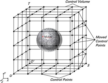
The free deformation method (FFD) regards the geometric structure as an elastic object and embeds it into a parallel hexahedron, which is called the control volume, and the vertices (nodes) of the hexahedron distributed on the control body are the control points. The function mapping relationship between the control points and the internal object is formed, so the deformation operation of the target geometry can be realised by changing the position of the control points. Figure 1 shows that a sphere is embedded in the control body by free deformation technique, and the shape of the internal sphere is changed by changing the distribution of control points [Reference Yu35].
Example of sphere FFD deformation [Reference Yu35].

2.1 FFD basic theory
The key of the FFD method is to embed the deformable object in the variability control body. In order to introduce the principle, firstly, it is assumed that there are l + 1, m + 1, n + 1 control points in the three perpendicular directions on the control body, and the basic function is expressed uniformly in R, then the principle of the FFD method can be expressed in the form of Equation (1) [Reference Cao36].
 \begin{align}{\boldsymbol{x}_g}(s,t,u) = \sum\limits_{i = 0}^l {\sum\limits_{j = 0}^m {\sum\limits_{k = 0}^n {{R_i}(s)} } } {R_j}(t){R_k}(u){\boldsymbol{P}_g}_{i,j,k}\end{align}
Among which,  ${\boldsymbol{P}_g}_{i,j,k}$ is the control points coordinates,
 ${\boldsymbol{x}_g}$ coordinates of parameterised object, the subscript g represents global coordinates.
 $(s,t,u)$ is the local coordinate of the control body,
 $s \in [0,1],{\rm{ }}t \in [0,1],{\rm{ }}u \in [0,1],{\rm{ }}$and their relative positions in the local coordinate system remain unchanged. The concepts of local coordinates and global coordinates are easy to be confused, which are described in detail below.
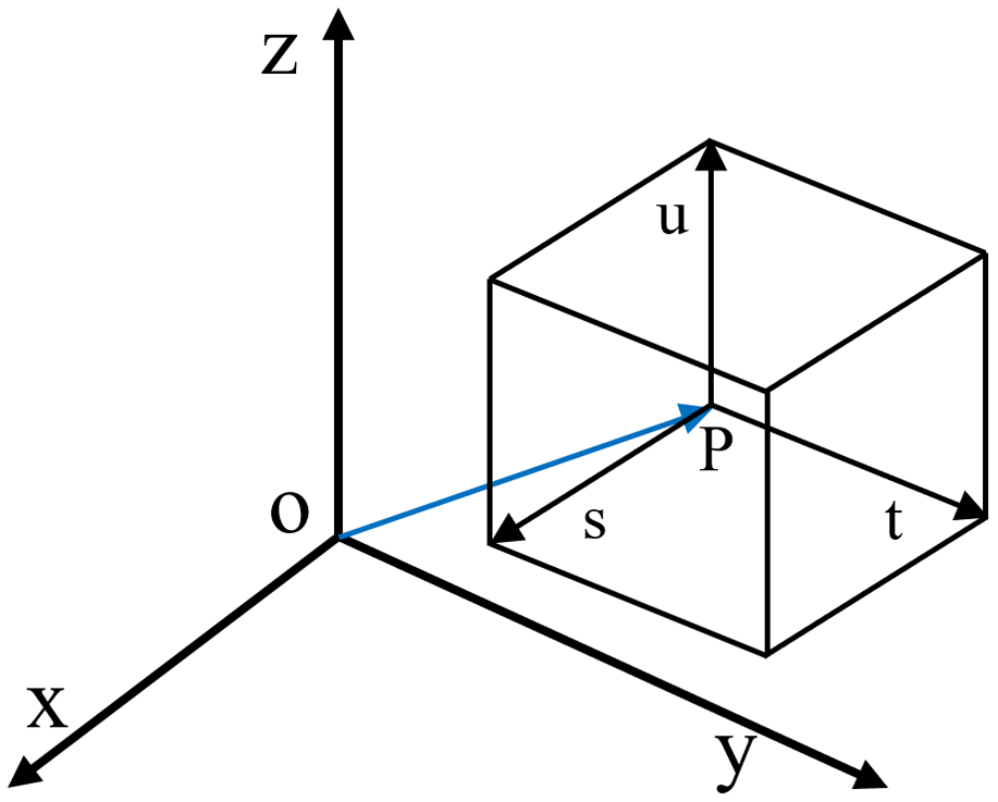
As shown in Fig. 2, the xyz coordinate system with the origin O is the global coordinate system, which is the initial existence coordinate system of the parameterised object. While the stu coordinate system with P as the origin is the local coordinate system,  $ \mathop{\rm OP}\limits^\rightharpoonup $ and is the starting point deviation vector of the two coordinate systems. The FFD method first converts the parameterised object from the global coordinate system to the local coordinate system, and keeps the local coordinates unchanged in the process of deformation. The transformation relationship can be expressed as an Equation (2) [Reference Zhang37].
 \begin{align} s &= \frac{{\boldsymbol{T} \times \boldsymbol{U} \cdot (\boldsymbol{X} - {\boldsymbol{X}_0})}}{{\boldsymbol{T} \times \boldsymbol{U} \cdot \boldsymbol{S} }} \nonumber\\[5pt] t &= \frac{{\boldsymbol{U} \times \boldsymbol{S} \cdot (\boldsymbol{X} - {\boldsymbol{X}_0})}}{{\boldsymbol{U} \times \boldsymbol{S} \cdot \boldsymbol{T}}}\nonumber\\[5pt] u &= \frac{{\boldsymbol{S} \times \boldsymbol{T} \cdot (\boldsymbol{X} - {\boldsymbol{X}_0})}}{{\boldsymbol{S} \times \boldsymbol{T} \cdot \boldsymbol{U} }} \nonumber \\[5pt] \boldsymbol{X} &= {\boldsymbol{X}_0} + s\boldsymbol{S} + t\boldsymbol{T} + u\boldsymbol{U} \end{align}
Schematic diagram of the relationship between global and local coordinates.

Among which, X is global position vector of object point, and X 0 is the position vector of the origin of the local coordinate system relative to the origin of the global coordinate system. STU is the three axis directions of the local coordinate system. It is worth mentioning that the transformation between local and global coordinates has a certain flexibility. In actual operation, the coordinates of control objects and control points can be normalised or converted into local coordinates, and then converted back to the original coordinates after the deformation operation is completed.
Through Equations (1) and (2), it can be seen that the FFD parameterisation method needs to transform between local and global coordinates, and needs to be superimposed repeatedly. In order to improve the computational efficiency, the formula of FFD principle can be rewritten into matrix form.
 \begin{align} {\boldsymbol{x}_g} &= \boldsymbol{R} \cdot {\boldsymbol{P}_g} \nonumber \\[5pt] \Delta {\boldsymbol{x}_g} & = \boldsymbol{R} \cdot \Delta {\boldsymbol{P}_g} \end{align}
The matrix R is determined by the basic function and the local coordinates of the deformed object. Because the local coordinates of the object remain constant in the whole deformation process, the matrix R can be calculated by one-time solution, which avoids the computational resource consumption caused by repeated iterations in the deformation process. Thus, it can be seen that the essence of FFD method is the process of superimposing the coordinates of control points to get object points, and different basic functions determine the different ways to calculate the weight of control points.
2.2 Basic function comparison
There are three common FFD parameterisation basic functions, namely, Bernstein basic function, B-spline basic function and NURBS basic function. As shown in Equation (3), different basic functions determine the different forms of matrix R leading different parameterisation effects. It is necessary to compare and make a choice.
Before establishing the basic function, we need to make clear the basic requirements. Taking s direction as an example, we need to satisfy that the sum of all orders of the function under the same local coordinates is equal to 1.
 \begin{align}\sum\limits_{i = 0}^l {B_i^l} (s) = 1\end{align}
2.2.1 Bernstein basic function
Bernstein basic function is the basic function originally used in FFD method. Its form is simple, and it is convenient to calculate matrix directly in computer. It is also the most widely used basic function in FFD method at present. Its specific form is given by Equation (5) [Reference Zhang, Wang and Huang38].
 \begin{align}\left\{ {\begin{array}{*{20}{l}}{B_l^i(s) = \dfrac{{l!}}{{i!(l - i)!}}{s^i}{{(1 - s)}^{l - i}}}\\[7pt] {B_m^j(t) = \dfrac{{m!}}{{j!(m - j)!}}{t^j}{{(1 - t)}^{m - j}}}\\[7pt] {B_n^k(u) = \dfrac{{n!}}{{k!(n - k)!}}{u^k}{{(1 - u)}^{n - k}}}\end{array}} \right.\end{align}
Herein,  $l,{\rm{ }}m,{\rm{ }}n$ is the order of the function, and
 $i = 0,1, \cdots ,l{\rm{ }};\; j = 0,1, \cdots ,m\; ;\; k = 0,1, \cdots ,n.$ At this point, the FFD parameterisation method can be expressed as follows.
 \begin{align}x(s,t,u) = \sum\limits_{i = 0}^l {\sum\limits_{j = 0}^m {\sum\limits_{k = 0}^n {{P_{i,j,k}}B_l^i} } } (s)B_m^j(t)B_n^k(u) = \sum\limits_{i = 0}^l {\sum\limits_{j = 0}^m {\sum\limits_{k = 0}^n {{P_{i,j,k}}{B_{i,j,k}}} } } \end{align}
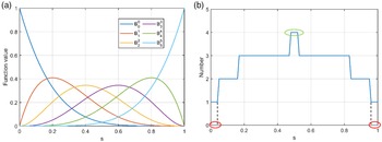
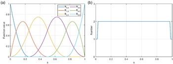
In order to explore the properties of Bernstein basic functions, taking s direction as an example, the numerical distribution map shown in Fig. 3(a) can be obtained by taking the order of the function as 5. It can be found that the different layer number i of the control points will lead to different control effect on the independent variable, and the maximum of the basic function appears in the position close to the relative layer number, which indicates that the control points have a more obvious control effect there.
Bernstein basic function correlation image with l = 5. (a) Function values distribution in different layers and (b) Control points required to reach the threshold.

At the end point, the property becomes special, and there is a basic function with the value of 1. According to Equation (4), the value of other five basic functions are all 0. It can be concluded that the outermost points on the object are only controlled by the outermost control points, while the internal control points cannot deform the outermost object points.
In the whole range of the independent variable s, except for the endpoint, the value of the basic function is not 0. Therefore, the change of the position of any control points will affect the coordinates of all the points on the internal object (except the outermost point), but the influence on different location points is different. In order to quantify the control ability of the control points to the object points to a certain extent, the function values corresponding to the object points in different positions are summed up, and the local control effect is reflected by the minimum number of control points required for each position to reach the specified threshold. The threshold set in this paper is 0.8, and the corresponding layer distribution of control points is shown in Fig. 3(b). It can be found from the figure that the closer the points are to the middle location, the more the number of control points needed to achieve the specified control effect, while the edge point only needs one control point to achieve the corresponding deformation, which is consistent with the above conclusion. As shown in the red circle area in Fig. 3(b), only one control point is needed to achieve the specified control effect, which means that only few control points can effectively control the object points at the edge location. The green circle area needs the largest number of control points to achieve the specified control effect. And with the Increase of the threshold, the red area will shorten, and the green area will become longer, because more control points are needed in order to achieve a more obvious control effect and the control effect of the outermost control points becomes more obvious as the position of the object points position moves outward. So the red circle area would shrink to a point for the limit case where the control effect threshold is 1, while the number of control points needed in all other locations is 6.
2.2.2 B-spline basic function
B-spline basic function is a generalisation of Bernstein basic function, as B-spline will be converted to Bernstein basic function when the node setting of B-spline conforms to a certain rule [Reference Zhu, Ma and Wang39]. Compared with Bernstein basic function, B-spline not only has better local deformation control ability, but also has a wider design space. Its function relation is given by Equation (7) [Reference Griessmair and Purgathofer19].
 \begin{align}\left\{ {\begin{array}{*{20}{l}}{{B_{i,1}}(s) = \left\{ {\begin{array}{*{20}{l}}{1, {{{u}}_i} \le s \lt {u_{i + 1}}}\\[5pt]
{0,\ {\mathop{\rm otherwise}\nolimits} }\end{array}} \right.}\\[12pt]
{{B_{i,k}}(s) = \dfrac{{s - {{{u}}_i}}}{{{{{u}}_{i + k - 1}} - {{{u}}_i}}}{B_{i,k - 1}}(s) + \dfrac{{{{{u}}_{i + k}} - s}}{{{{{u}}_{i + k}} - {{{u}}_{i + 1}}}}{B_{i + 1,k - 1}}(s),{\rm{ k}} \geq 2}\end{array}} \right.\end{align}
Herein,  $i = 0,1, \cdots ,l$ is the number of control points along s direction, k is the order, the degree of the corresponding function is k-1,
 ${{\rm{u}}_i}$ is the node, and its number is equal to the sum of the control points and the order of the function, namely (l + k + 1). In the calculation iteration, we define
 $0/0 = 0$. It can be seen from the analysis that the value of B-spline basic function is not 0 only in the interval
 $s \in {\rm{[}}{u_i},\; {u_{i + k}}{\rm{]}}$, while the values in other intervals are all 0, which is also the basis for realising local deformation control. In order to meet the basic requirements of FFD basic function proposed in Equation (4), it is necessary to set nodes according to the following rules [Reference Martin, Andres and Lozano20].
 \begin{align}\boldsymbol{u}_{s} = \left\{ {\underbrace {{\rm{0, }} \ldots .{\rm{ , 0}}}_k, \underbrace {{u_k}{\rm{, }} \ldots {\rm{ , }}{u_l}}_{l - k + 1},\; \underbrace {{\rm{1, }} \ldots .{\rm{ , 1}}}_k} \right\}\end{align}
Therefore, the order k and the number of control points l + 1 are the most important parameters affecting the B-spline basic function. In fact, when the intermediate elements are removed from the node vector  $u_s$ and only 0 and 1 of order k are retained, the B-spline basic function then becomes a Bernstein function.
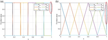
Before introducing the properties of B-spline basic functions, two special cases are described. The first is the order problem: the case of k = 1 is shown in Fig. 4(a). It can be seen that the function is in the form of approximate step and has lost the basic characteristics that B-spline basic functions should have, so k = 1 is not allowed in the definition. The case of k = 2 is shown in Fig. 4(b). The value of the function changes into a broken line, which means that the control effect of the control points on the surrounding object points is not continuous. Therefore, although k ≥ 2 is allowed in the definition of B-spline basic function, k = 2 is not recommended in the practical application of FFD method. The second problem is that the right end of the B-spline basic function is discontinuous: as shown in the red circle marked areas in Fig. 4(a) and (b), when the independent variable approaches 1, the function value will drop sharply to 0. As in the definition of Equation (7), the interval where  ${B_{i,1}}(s)$ takes 1 is left continuous and right discontinuous. In view of this, 1 item in the B-spline basis function node is replaced by 1+eps to perfectly solve this technical problem. And this technical treatment is generally applicable to other k values.
Two special cases of B-spline basic function. (a) B-spline basis function image with  $k=1$ and (b) B-spline basis function image with
 $k=2$.

In order to further explore the properties of B-spline basic function in FFD method, the s-direction function is also taken as an example. At the same time, in order to facilitate the comparison with the Bernstein basic function above, the number of control points l + 1 is set as 6, and the order k is taken as 3 as well. Figure 5(a) shows the image of the function. It can be found from the figure that the B-spline basic function and Bernstein basic function still have some similarities. The maximum value of B-spline basic function also appears near the number of layers corresponding to the control points, indicating that the control points are more effective for controlling the object points close to their positions. At the end point, there is only one basic function with the value of 1, so it also meets the characteristics that the points at the most edge of the object are only controlled by the outermost control points, which is consistent with the characteristics of Bernstein basic function. However, there are also many differences between B-spline basic function and Bernstein basic function. The most obvious one is that B-spline basic function has an interval with a value of 0, which means that the control points do not control all object points, but only control the surrounding local areas, and it is the fundamental source of its local control ability. On the other hand, the maximum value of B-spline basic function is significantly greater than Bernstein basic function, which indicates that the following property of deformation operation should be stronger. When the displacement of control points is the same, the movement effect of object points with control points will be more obvious.
Correlation image of B-spline basic function with k = 5. (a) B-spline basis function image with  $k=3$ and (b) Control points required to reach the threshold.

The calculation threshold in Fig. 5(b) is also taken as 0.8. Compared with Fig. 3(b), it can be found that the layers of control points required for object points at different positions to achieve the specified control effect are significantly smaller than Bernstein basic function. Especially in the middle position, Bernstein needs four layers of control points to achieve the control effect, while B-spline only needs two layers, which further reflects its good local deformation control ability.
2.2.3 NURBS basic function
NURBS (Nonuniform Rational B-Spline) is a method derived from B-spline basic function. Its definition formula is as shown in Equation (9).
 \begin{align}{N_{i,k}}(s) = \frac{{{\omega _{{\rm{ }}i}}{B_{i,k}}(s)}}{{\sum\limits_{i = 0}^{n - 1} {{\omega _{{\rm{ }}i}}{B_{i,k}}(s)} }},{\rm{ k}} \geq 2\end{align}
Herein,  ${B_{i,k}}(s)$ is B-spline basic function, so the definition of i and k is the same as that in Equation (7).
 ${\omega _{{\rm{ }}i}}$ is the weight coefficient introduced into NURBS basic function, which is the root of its difference from B-spline, and also determines the special properties of NURBS basic function. When the weight coefficients are all 1, NURBS becomes B-spline basic function. Therefore, the research on NURBS properties should focus on its weight coefficient
 ${\omega _{{\rm{ }}i}}$.
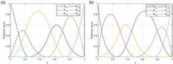
For comparison, the parameter settings of the basic function are exactly the same as those above (l = 5, p = 3). For the weight coefficient, we set  ${\omega _{{\rm{ }}a}} = [1,{\rm{ }}0.5,{\rm{ }}1,{\rm{ }}0.5,{\rm{ }}1,{\rm{ }}1]$ and
 ${\omega _{{\rm{ }}b}} = [1,\; 2,\; 1,\; 2,\; 1,\; 1]$ in Fig. 6(a) and (b).
NURBS function images with different weight coefficients. (a) NURBS function image with  $\omega_a=[1,0.5,1,0.5,1,1]$ and (b) NURBS function image with
 $\omega_b=[1,2,1,2,1,1]$.

It can be found from the figure that the coefficient  ${\omega _{{\rm{ }}i}}$ mainly affects the function value of the independent variable interval
 ${\rm{[}}{u_i},\; {u_{i + k}}{\rm{]}}$ without changing the zero interval range of the original B-spline basic function, which is consistent with the conclusion in Ref. (Reference Lepine, Guibault and Trepanier40). In addition, when the coefficient
 ${\omega _{{\rm{ }}i}}$ increases, the value of the function on the interval
 ${\rm{[}}{u_i},\; {u_{i + k}}{\rm{]}}$ raises accordingly, resulting in the function becoming smaller on the intervals
 ${\rm{[}}{u_{i - 1}},\; {u_{i + k - 1}}{\rm{]}}$ and
 ${\rm{[}}{u_{i + 1}},\; {u_{i + k + 1}}{\rm{]}}$ on both sides, and vice versa. This indicates that
 ${\boldsymbol{\omega} _{{\rm{ }}i}}$ will affect the deformation control ability of the corresponding control points. Therefore, NURBS is an extended form of B-spline basic function, which adjusts the control ability of different control points by introducing the weight coefficient vector
 ${\boldsymbol{\omega} _{{\rm{ }}i}}$. And
 ${\boldsymbol{\omega} _{{\rm{ }}i}}$ provides a new fitting adjustment parameter, which increases the flexibility of control point distribution. Its disadvantage is that the function is more complex than Bernstein and B-spline, which increases the calculation consumption during fitting. When the number of control points and object points is large, it will even lead to fitting failure.
In this chapter, by analysing the numerical distribution of the three basic functions in the same direction, their basic characteristics are systematically described. It is found that Bernstein basic function is simple to calculate and has high expression accuracy, but it is difficult to achieve local deformation, and the deformation range is terribly small. While for B-spline, the greatest advantage is that it owns good local expression and deformation control ability, but it should pay more attention to the order and node setting. NURBS is an extension of the concept of B-spline, on the basis of which the weight coefficient is introduced, making the control ability of control points more flexible and controllable, but its computational complexity increases simultaneously. At the same time, it also digs out the different effects that may be produced by the application of three different basic functions in the FFD parameterisation method, which lays a foundation for the further investigation and application of the three-dimensional lifting body configuration below.
3.0 Comparison of FFD method in parametric modeling of a lifting body
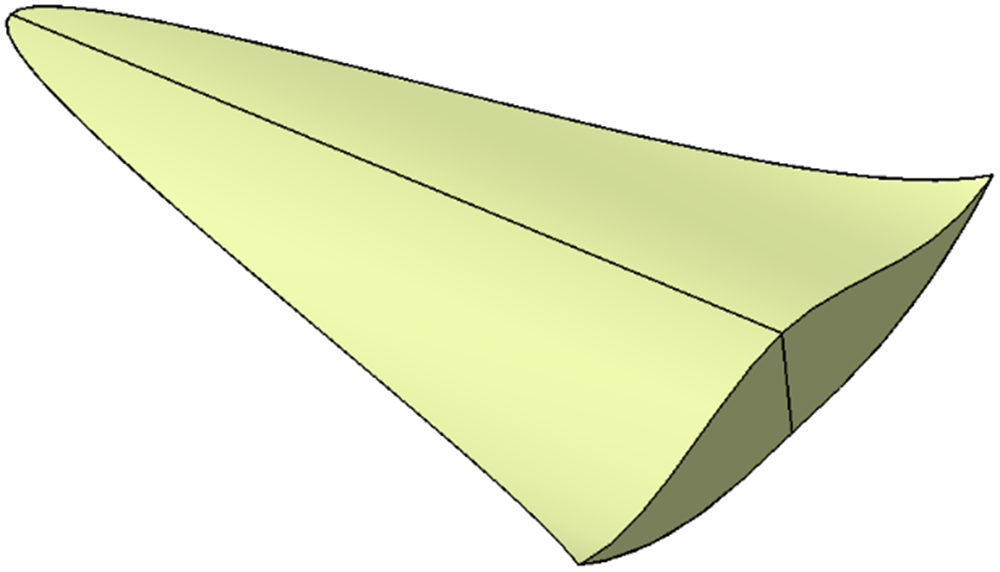
The parameterisation object in this paper is a lifting body. In order to make it have better aerodynamic performance, its initial shape adopts a waverider like configuration. For the specific details of the design method, refer to Ref. (Reference Li, Li and Huang41). Figure 7 shows the lifting body configuration used in this paper.
Lifting body configuration of waverider-like body.

3.1 Parametric representation
3.1.1 Uniform distribution of control points
Three FFD methods with different basic functions will be used to parameterise this configuration in the following. In this modeling, the control points are arranged according to the principle of uniform distribution, and then the orders of B-spline basic functions in the three directions of local coordinate system STU are set to 4, 3 and 3, respectively, which gives consideration to both accuracy and speed of modeling to some extent. The order setting of NURBS basic function in three directions is the same as B-spline, and the emphasis of this method is the optimisation of weight coefficient vector  ${\boldsymbol{\omega} _{{\rm{ }}i}}$.
The optimisation goal adopted in this paper is to minimise the average distance deviation between the object points generated by parametric modeling and the original object points. The specific calculation method is shown in Equation (10).
 \begin{align}\left\{ \begin{array}{l}{\varepsilon ^2} = \varepsilon _x^2 + \varepsilon _y^2 + \varepsilon _z^2\\[5pt] \varepsilon _x^2 = \dfrac{1}{n}\left( {\sum\limits_{i = 1}^n {{{{\rm{(}}{x_i} - x_i^*{\rm{)}}}^2}} } \right)\\[10pt] \varepsilon _y^2 = \dfrac{1}{n}\left( {\sum\limits_{i = 1}^n {{{{\rm{(}}{y_i} - y_i^*{\rm{)}}}^2}} } \right)\\[10pt] \varepsilon _z^2 = \dfrac{1}{n}\left( {\sum\limits_{i = 1}^n {{{{\rm{(}}{z_i} - z_i^*{\rm{)}}}^2}} } \right)\end{array} \right.\end{align}
Herein,  $\varepsilon _x^2\,\varepsilon _y^2\,\varepsilon _z^2$ is the square of deviation value of average distance in the direction of the three axes of xyz, and
 ${\varepsilon ^2}$ is the square of total deviation. n is the number of target object points.
 ${x_i}\,{y_i}\,{z_i}$ is the three coordinate values of the object points obtained by parameterised expression, and
 $x_i^*\,y_i^*\,z_i^*$ is the original coordinate value of the object points.
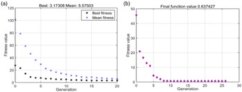
In the previous research, Zhang et al. [Reference Zhang, Guo and Dai42] adopted Broyden-Fletcher-Goldfarb-Shanno algorithm (BFGS) to optimise the weight coefficient when using the NURBS method to fit the two-dimensional curve, in which the functional gradient information needed was calculated by the independent variable perturbation method, realising the NURBS curve fitting successfully, and found that the fitting effect of NURBS was better than that of Bezier and B-spline curves. However, the design object of this paper is a three-dimensional object, and the number of control points is much more than the above case. After trying, it is found that the gradient cyclic iterative method in Ref. (Reference Zhang, Guo and Dai42) is not suitable for this problem. It works with a very slow convergence speed, and it is easy to fall into local optimisation. As the number of independent variables of this optimisation is 14(6 + 5 + 3), the intelligent optimisation algorithm converges slowly. This paper then tries several mainstream optimisation algorithms, such as nelder-mead simplex method [Reference Lagarias, Reeds and Wright43], interior point method [Reference Byrd, Gilbert and Nocedal44] and sequential quadratic programming algorithm (SQP) [Reference Powell45]. After comprehensive comparison and analysis, it is found that the combinatorial optimisation algorithm is more suitable for the optimisation of weight coefficient vector  ${\boldsymbol{\omega} _{{\rm{ }}i}}$ in this modeling. This calculation first carries on 20 generations of genetic algorithm as the preliminary calculation, and then uses the SQP algorithm to continue. Such not only can play an intelligent algorithm to find the global optimal ability, also can embody the SQP’s advantage in dealing with the small and medium-sized issue effectively. The optimisation process of genetic algorithm and SQP algorithm is shown in Fig. 8, in which “function value” represents the square of the difference between the average distance of the parameterised object point cloud and the parameterised point cloud (see Equation (9)).
Whole process of combinatorial optimisation. (a) Initial optimization process of genetic algorithm and (b) Further optimization process of SQP algorith.

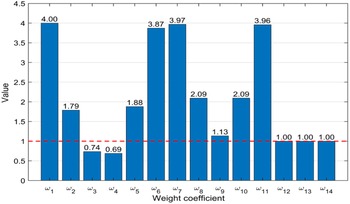
Figure 9 shows the optimisation results, where  ${\omega _{{\rm{ }}1}}\sim {\omega _{{\rm{ }}6}}$ is the weight coefficient of the NURBS basic function in the s direction, while
 ${\omega _{{\rm{ }}7}}\sim {\omega _{{\rm{ }}11}}$ and
 ${\omega _{{\rm{ }}12}}\sim {\omega _{{\rm{ }}14}}$ are the weight coefficients corresponding to the t and u directions, respectively. The red line represents the initial value of the weight coefficient. It can be seen in the figure that
 ${\omega _{{\rm{ }}1}}\sim {\omega _{{\rm{ }}11}}$ changes obviously, but
 ${\omega _{{\rm{ }}12}}\sim {\omega _{{\rm{ }}14}}$ does not. This is because the error of the corresponding BFFD method in
 $ \boldsymbol{z} $ direction is also very small when the weight coefficients are all 1, so the weight coefficients of the corresponding NURBS basic function in u direction can meet the accuracy requirements without changing.
Numerical distribution of weight coefficients in three directions.

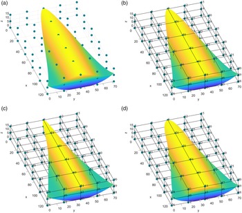
Figure 10 shows the original object configuration and the configuration expression results obtained by three parameterised modeling methods. It can be found that the control points with uniform distribution are also used though, the expression effect is not the same. Equation (3) can explain the cause of this phenomenon to some extent. The essence of FFD method is to superimpose the coordinates of control points to get new object points, and the weight coefficient of superposition depends on the matrix R, and its value is related to the basis function and the local coordinates of the original object points.
Comparison of different FFD parameterisation effects of under uniform control points. (a) Original lifting body configuration, (b) Configuration expression of traditional FFD, (c) Configuration expression of BFFD and (d) Configuration expression of NFFD.

The expression effects of traditional FFD method, BFFD method and NFFD method are compared with the original configuration in Fig. 10(a). The specific values of parametric modeling errors are given in Table 1. It can be seen from the table that, given the uniformly distributed control points, the classical FFD method has the highest accuracy, whose error can be basically ignored (the error value in the table is likely to be the computer calculation error, but not the method itself). The accuracy of NFFD method is second, and the shape distortion of the lifting body head can also be observed from Fig. 10(d). However, the error of parametric modeling of BFFD method is very large, and it can hardly express the original configuration correctly. However, if the order of the B-spline basic function in three directions is set to 2, the BFFD method can also achieve accurate expression of the configuration under the condition of uniform distribution control points. As described in the previous section, nevertheless, such an order setting is not recommended.
3.1.2 Non-uniform and flexible distribution of control points
In the case of uniform distribution of control points, we have concluded that only the classical FFD parameterisation method based on Bernstein basic function can accurately express the original configuration, followed by the NFFD method that adjusts the fitting accuracy through weight coefficients, and the BFFD method has the worst accuracy. Therefore, it is necessary to change the distribution of control points for BFFD method meeting the requirements of accurate expression (CP-BFFD, CP represents the new distribution of control points).
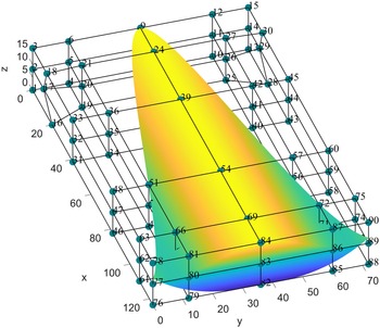
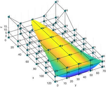
In this study, the number of control points is 90 (6 × 5 × 3), besides, each control points corresponds to three coordinate variables, so the optimisation process has a considerable scale. In this paper, according to the fitting effect in Fig. 10(c) and the fitting error values shown in Table 1, the z coordinate of the control points is limited to be unchanged leaving the xy coordinate changeable. What’s more, the positions can only be changed near the uniformly distributed control points to prevent the generation of invalid control volume frames. The optimisation algorithm adopts Levenberg-Marquardt algorithm [Reference More46], which ignores the derivative term of fixed order, and the nonlinear least square problem is internally transformed into a linear problem, thus reducing the consumption of computing resources and converging quickly. After optimisation, the distribution of the new control points and the configuration expression effect are shown in Fig. 11. From the figure, it can be found that the overall distribution of the control points has been changed, and the two control layers near the middle in the y-axis direction move closer to the edge as a whole, which solves the problem of narrow overall width of the lifting body expressed in Fig. 10(c). And the change in the distribution of the second layer control points in the x-axis direction is the most obvious. It is easy to observe that the positions of control points 16, 17, 18 and 28, 29, 30 have changed obviously, thus solving the problem that the configuration head is too sharp. The error of CP-BFFD parametric fitting is shown in Table 2. It can be found that the expression accuracy of CP-BFFD method is obviously improved after changing the distribution of control points, which can meet the requirements of 3D lifting body configuration parameterisation.
Parametric modeling error of FFD method with different basis functions

Parameterised representation effect of CP-BFFD method.

3.1.3 Flexible distribution of local coordinates of object points
In the fitting calculation of BFFD parameterisation, the design variables include the coordinates of both the control points and the object points. So in theory, it can be fitted not only by changing the control points, but also by adjusting the local coordinates of the object points. However, in parametric modeling, the coordinates of objects are generally given, so it is difficult to carry out parametric modeling by adjusting the real coordinates of objects. Therefore, a new idea of parametric modeling and simulation is proposed in this paper, which regards the specified configuration and control points distribution as the result of the deformation of an unknown configuration and the corresponding control point distribution of the B-spline basic function. The key point of the method is to inversely solve the unknown configuration and control point distribution before deformation. This method is named as p-BFFD (in which p represents the object coordinates obtained by reverse solution).
First of all, it is assumed that the global location coordinates of the unknown configuration and its corresponding control points are  $\boldsymbol{x}_g^*$ and
 $\boldsymbol{P}_g^*$, respectively. According to Equation (3), we can get
 \begin{align}\boldsymbol{x}_g^* = \boldsymbol{R}{\rm{(}}\boldsymbol{x}_g^*{\rm{)}} \cdot \boldsymbol{P}_g^*\end{align}
Herein,  $\boldsymbol{R}{\rm{(}}\boldsymbol{x}_g^*{\rm{)}}$ means that the value of
 $\boldsymbol{R}$ depends on
 $\boldsymbol{x}_g^*$. Because the local coordinate of the object points corresponding to
 $\boldsymbol{R}$ depends on its global coordinate,
 $\boldsymbol{R}$ ultimately depends on the global coordinate of the object point
 $\boldsymbol{x}_g^*$.
Parametric modeling error of improved BFFD method

Under the control of the control points, the object points are deformed. The coordinates of the deformed object points are solved as Equation (12).
 \begin{align}\boldsymbol{x}_g^* + \Delta \boldsymbol{x}_g^* = \boldsymbol{R}{\rm{(}}\boldsymbol{x}_g^*{\rm{)}} \cdot (\boldsymbol{P}_g^* + \Delta \boldsymbol{P}_g^*)\end{align}
At this time, the control points should be moved to the coordinate positions specified by us, and the coordinates of the deformed object manipulated by the control points are exactly the configuration point cloud specified by us, so
 \begin{align} \boldsymbol{x}_g^* + \Delta \boldsymbol{x}_g^* &= \boldsymbol{x}_{g} \nonumber\\[5pt] \boldsymbol{P}_g^* + \Delta \boldsymbol{P}_g^* &= \boldsymbol{P}_{g} \end{align}
Herein,  ${\boldsymbol{x}_g}$ and
 ${\boldsymbol{P}_g}$ are respectively the point cloud coordinates of the parameterised modeling target object and the corresponding uniformly distributed control points coordinates. Therefore, the final deformation form of the unknown configuration and control points can be obtained as follows.
 \begin{align}{\boldsymbol{x}_g} = \boldsymbol{R}{\rm{(}}\boldsymbol{x}_g^*{\rm{)}} \cdot {\boldsymbol{P}_g}\end{align}
In the above description, we regard  ${\boldsymbol{x}_g}$ and
 $\boldsymbol{x}_g^*$ as matrices containing the coordinates of all object point cloud. Its size is
 $n \times 3$, and n is the number of points, usually thousands or tens of thousands. In this modeling, it is 2,402. Under this scale of independent variables, if Equation (13) is directly solved, the consumption of computing resources will be very serious, and even cannot be solved successfully. In addition, the B-spline basis function is in the form of piecewise iteration, and its analytical solution cannot be obtained. Therefore, the method of solving object points one by one is adopted using Levenberg Marquardt algorithm, which is the same algorithm as the control points solving in the previous section. The distribution of the original object point cloud coordinates
 $\boldsymbol{x}_g^*$ and the corresponding control point coordinates
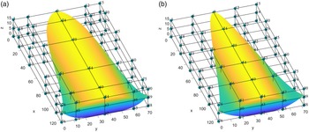
 $\boldsymbol{P}_g^*$ is shown in Fig. 12(a), while the parameterised object and uniform control points distribution effect obtained after deformation are shown in Fig. 12(b). In other words, by shifting the control points in Fig. 12(a) to the positions in Fig. 12(b), the configuration in (a) can also be changed into the style in (b).
Structural styles obtained by inverse solution before and after deformation. (a) Original objects and control point distribution and (b) Parameterized object and control point distribution.

To further test the accuracy of the inverse algorithm of object point parameterised solution, the deformed object point cloud is compared with the real point cloud, and the error is shown in Table 2. It can be found that its solution accuracy is very high, and it can also meet the needs of accurate parametric expression.
3.2 Parametric deformation
It is a prerequisite for a good parameterised method to realise efficient parameterised deformation on the basis of parameterised precise expression. A good deformation control effect is very important for the efficient implementation of parameterisation itself and the subsequent structural optimisation processes that may be involved. Because in the same control points design space, the parameterisation method with strong deformation ability provides more possibilities for the structural style, or the control deformation range including the optimal configuration can be achieved with a smaller control points design space. Furthermore, it can effectively reduce the consumption of computing resources. The following shows and compares the deformation ability of FFD parameterisation methods with different basic functions.
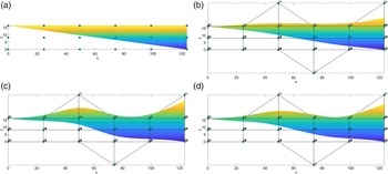
In order to better compare the deformation effect, the control points displacement of different methods is set to the same. Because the expression of BFFD method is distorted in the case of uniformly distributed control points, p-BFFD method is used instead. Change the local coordinates in the u direction of control points No. 39 and 84 from 1 to 2, and change No. 52 from 0 to −1 (see Figs. 10 and 12 for the location of control points). After the positions of control points are changed, the effect of object configuration change is shown in Fig. 13.
Comparison of deformation effects of different parameterisation methods. (a) Side view of original object and control points, (b) Side view of deformation effect of classic FFD, (c) Side view of deformation effect of p-BFFD and (d) Side view of deformation effect of NFFD.

Comparing the deformation effects of Fig. 13(b), (c) and (d) with the original configuration in Fig. 13(a), it can be found that for all the three FFD methods, the control points have the most obvious deformation control effect on the object points near their positions, and moreover, the problem that one control point can cause the deformation of both the upper and lower surfaces at the same time is revealed. However, when the displacement of control points is the same, the control effects of different methods are obviously different. Comparing the deformation effects of (b), (c) and (d) in Fig. 13 with the original configuration in (a), it can be found that the classical FFD method has the least obvious control effect, followed by NFFD method, and the p-BFFD method has the most obvious deformation effect. This can be explicated by the fact the weight coefficient of NFFD method is compromised in the process of parametric fitting, and the deformation control effect cannot be guaranteed to be as stable as the BFFD method whose weight coefficient are all 1.
Combining the effect of parameterised expression and parameterised deformation, it can be found that the classical FFD method can achieve good configuration expression effect, but its local deformation ability is limited, and the deformation range is poor. The accuracy of parameterised expression of NFFD method is insufficient. Although the effect of parameterised deformation of NFFD method is better than that of classical FFD method, its deformation effect is not stable due to the compromise of weight coefficient. BFFD method based on uniform control points distribution cannot achieve the correct expression of configuration, but the improved p-BFFD method with reverse solution idea can not only meet the requirements of parametric expression accuracy, but also has strong deformation ability. It is a very potential parametric method at present.
4. A new parameterisation method EDGE-p-BFFD for the lifting body
It can be seen from the third section that, with the blessing of the idea of reverse solution, the p-BFFD method based on B-spline basic function is an excellent parameterisation method, which has good results in parameterisation expression and deformation control. However, since the control points are specified as uniformly distributed in Section 3.2, there are still some problems.
The first is the problem of invalid control points. The control points far away from the object configuration can hardly control the parameterised object. However, the particularity of the lifting body configuration with narrow head and wide tail means that many control points are far away from the lifting body configuration when placed in the cuboid control body. For example, in Fig. 12(b), control points 1∼6, 16∼18, 31∼33, 46∼48 and their symmetrical positions are far away from the lifting body configuration, and their control ability for parameterised objects is very limited. Therefore, it is a waste of control points and computing resources. In order to further test its deformation control ability, the u-direction coordinates of control points 3, 15, 18 and 30 are now shifted from 1 to 2. The configuration and distribution of control points after deformation are shown in Fig. 14, and almost no difference can be seen. The position deviation values are shown in Table 3 (p-BFFD’ in the table is the deformation operation after p-BFFD parameterised expression). Although the position deviation slightly increases compared with Table 2, it is still an acceptable order of magnitude.
Control rendering of control points away from the configuration.

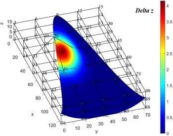
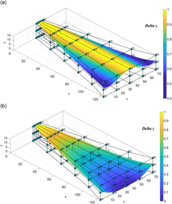
The second is the problem of discontinuous deformation at the edge of the lifting body. As shown in Fig. 13, the effect on the lifting body configuration is shown in Fig. 15 if the control point 36 is shifted upward by a unit distance in the p-BFFD method where the control points are uniformly distributed. The different colors in the figure represent the deviation of z coordinates of the object point cloud before and after deformation (represented by Delta z). It can be found that the deformation terminates suddenly at the edge of the lifting body leading to the deformation of the guideline. It is easy to cause sharp changes in aerodynamic or thermodynamic performance and lose the characteristics of quasi-multiplicative waves, which are not expected in the process of deformation optimisation.
The third is the problem that the control points cause the upper and lower surfaces deforming at the same time. In Fig. 13, for example, control point 39 not only stretches the upper surface of the lifting body upward, but also drives the upwind to move closer, and even the p-BFFD method with the best local control ability cannot avoid this problem.
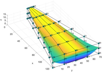
In this paper, an EDGE-p-BFFD parameterisation method based on edge control is proposed, which can solve the first two problems to some extent by aggregating the positions of control points into the contour of the lifting body. The configuration expression effect obtained by this method is shown in Fig. 16. In order to further test its parameterised expression accuracy, the error of point cloud positions are shown in Table 3 expressing that its accuracy is very high and meeting the requirements of parameterisation.
On the basis of the EDGE-p-BFFD method, in order to solve problem 3, this paper then proposes the double control body frames, using two control body frames of the same size to model the upper and lower surfaces of the lifting body, respectively. However, in calculation, attention should be paid to the normalisation of different surface coordinates and the translation of the point cloud in the control body. The following formula can be referred to.
For the upper surface
 \begin{align}\begin{array}{l}{x_{\rm u,range}} = \max\! ({\boldsymbol{x}_u}) - \min\! ({\boldsymbol{x}_u})\\[5pt] {y_{\rm u,range}} = \max\! ({\boldsymbol{y}_u}) - \min\! ({\boldsymbol{y}_u})\\[5pt] {z_{\rm u,range}} = \max\! ({\boldsymbol{z}_u}) - \min\! ({\boldsymbol{z}_l})\end{array}\end{align}
For the lower surface
 \begin{align}\begin{array}{l}{x_{\rm l,range}} = \max\! ({\boldsymbol{x}_l}) - \min\! ({\boldsymbol{x}_l})\\[5pt]
{y_{\rm l,range}} = \max\! ({\boldsymbol{y}_l}) - \min\! ({\boldsymbol{y}_l})\\[5pt] {z_{\rm l,range}} = \max\! ({\boldsymbol{z}_u}) - \min\! ({\boldsymbol{z}_l})\end{array}\end{align}
Herein,  ${\boldsymbol{x}_{\rm u}}\,{\boldsymbol{y}_{\rm u}}\,{\boldsymbol{z}_{\rm u}}$ and
 ${\boldsymbol{x}_{\rm l}}\,{\boldsymbol{y}_{\rm l}}\,{\boldsymbol{z}_{\rm l}}$ are the point cloud coordinates of upper and lower surfaces of the lifting body, respectively. The lower subscript
 ${\rm{range}}$ represents the corresponding coordinate value range. You can find
 ${z_{\rm u,range}} = {z_{\rm l,range}}$, which is to prevent the separate upper or lower surface from filling up the whole control body, resulting in the failure to correctly combine the upper and lower surfaces into the same control body.
Expression accuracy of EDGE-p-BFFD and p-BFFD

Control effect of control point No. 36 on lifting body configuration.

Effect of EDGE-p-BFFD expression on lifting body configuration.

After the normalisation of the coordinates is realised, the starting point of the upper and lower surfaces will be the origin of the local coordinate system of the control body leading to the coincidence of the surface after merger. Thus, it is necessary to translate the upper surface upward to the top position of the control body. The method of operation is as Equation (17).
 \begin{align}\boldsymbol{z}_{\rm u,stead}^* = \boldsymbol{z}_{\rm{u}}^* + (1 - \max\! (\boldsymbol{z}_{\rm{u}}^*))\end{align}
Herein,  $\boldsymbol{z}_{\rm{u}}^*$ are the normalised local coordinates of the upper surface, and
 $\boldsymbol{z}_{\rm u,stead}^*$ are their local coordinates after being translated to the top of the control body.
According to the above formulas, two control bodies of the same size can be established, and the distribution of the upper and lower surfaces is consistent with the configuration distribution of the original lifting body, which is convenient for subsequent merging. The frames and surface modeling effect of the two control bodies is shown in Fig. 17. In the deformation operation, the operating object are still the control points on the original frame. The change of the uppermost control points are transferred to the new control body corresponding to the upper surface, and accordingly, the change of the lowest control points are transferred to the corresponding control body of the lower surface. Then, two control bodies of the same size are merged to obtain a complete configuration of the lifting body. Therefore, the deformation coupling problem of control points for different surface manipulation can be avoided, and the individual fine control of control points to the upper and lower surfaces can be realised.
The schematic diagram of parameterised expression of the upper and lower surfaces of the lifting body. (a) Schematic diagram of the upper surface and (b) Schematic diagram of the lower surface.

5. Results and discussion
In view of the EDGE-p-BFFD parameterisation method applied to the lifting body proposed in this paper, the effects and advantages of the model are analysed from several aspects.
5.1 Comparison of control points utilisation
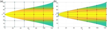
Figures 14 and 15 have confirmed that there are some control points that cannot be controlled or the deformation effects that need to be avoided in practical application when parameterised modeling uses p-BFFD method, so the effective control points and invalid control points are distinguished. As shown in Fig. 18, the red dots in the figure represent effective control points, while the others are invalid control points. It can be seen that the distribution of effective control points in EDGE-p-BFFD method is more concentrated and the number is more.
Schematic diagram of effective control points distribution of two BFFD extension methods. (a) Distribution of effective control points in p-BFFD and (b) Distribution of effective control points in EDGE-p-BFFD.

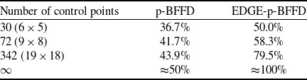
Because each control points in Fig. 18 has the same number of control points in the z direction, the proportion of the corresponding control points on the x-y plane can represent the proportion of all control points. The advantage of effective control points percentage increases as the number of control points increase.
Table 4 shows the percentage data of effective control points in different parameterisation methods. In the case of the control points distribution in this paper, the proportion of effective control points of EDGE-p-BFFD method is 50%, which is significantly higher than 36.7% of p-BFFD. With the increase of the number of control points, the proportion of effective control points of the two parameterisation methods both increased, but the improvement effect of EDGE-p-BFFD is more obvious. When the number of control points approaches infinity, the effective proportion of the EDGE-p-BFFD method is close to 100%, while that of the p-BFFD method is only about 50%. Thus, it can be seen that the proportion of effective control points of the EDGE-p-BFFD method proposed in this paper is much higher than that of the p-BFFD method, and the advantage of effective control points percentage increases as the number of control points increase.
5.2 Comparison of deformation effect
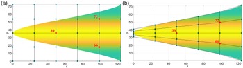
In order to compare the deformation effects of p-BFFD and EDGE-p-BFFD, the control points corresponding to the two methods are moved by the same distance in the same direction. The position distribution of control points for this deformation is shown in Fig. 19.
Effective control points percentage data by p-BFFD and EDGE-p-BFFD

Distribution of control points with displacement by two parameterisation methods. (a) Displacement control points in p-BFFD and (b) Displacement control points in EDGE-p-BFFD.

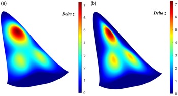
Both of the parameterisation methods change the positions of control points 39, 66 and 72 in the local coordinate u direction from 1 to 2, and the resulting deformation effect is shown in Fig. 20.
Comparison of deformation effects between two parameterisation methods. (a) Deformation effect of p-BFFD and (b) Deformation effect of EDGE-p-BFFD.

From Fig. 20(a), it can be seen that the deformation area caused by the control points in the p-BFFD method is approximately circular and has a wider range of action. Figure 20(b) shows that the deformation area of the EDGE-p-BFFD method is approximately elliptical and can approximate the configuration of the lifting body, so the deformation should be more reasonable for the improvement of performance.
From the view of deformation continuity, the p-BFFD method has a larger deformation range. Therefore, the deformation extends beyond the edge line of the lifting body, resulting in the discontinuity of deformation. The EDGE-p-BFFD method can realise that the deformation region is only concentrated in the interior of the lift surface, which ensures the continuity of the configuration.
The bottom side view of the original method after deforming.

The bottom side view of the improved method after deformation.

Deformation effect of lifting body configuration. (a) 3D view of lifting body. (b) Side view of lifting body, (c) Top view of lifting body and (d) Bottom view of lifting body.

From the perspective of deformation amplitude, the two methods is basically the same at the middle of the head of the configuration. For the two control points near the tail, the displacement of the configuration controlled by the EDGE-p-BFFD method is significantly greater than that of the p-BFFD method. This is because the positions of the control points of the former is closer to the symmetry plane of the lifting body, and the distance between the control points and the control object is closer. Therefore, although B-spline basis functions are used in both of the two methods, EDGE-p-BFFD proposed in the text can achieve better deformation effect.
5.3 Independent deformation of upper and lower surfaces
In Fig. 20(b), we see a very satisfactory deformation effect from the upper surface perspective. However, in fact, it is faced with the problem of deformation coupling, which will cause deformation on the lower surface of the lifting body while changing the position of the upper control points, as shown in Fig. 21.
It can be seen from Fig. 21 that the three control points all lead to deformation of varying degrees on the lower surface, especially near the head of the fuselage. After adopting the independent deformation method of the upper and lower surfaces based on the double control body frames in Section 4, the deformation effect is shown in Fig. 22. It can be seen that the lower surface of the lifting body is not affected by the uppermost control points at all, maintaining the initial structure.
In order to further explore the deformability of the improved method, the control points on the upper and lower surfaces are displaced at the same time, and the local coordinates in the u direction of control points 39 and 67 are changed from 1 and 0 to 2 and –1, respectively. The effect of the configuration change after deformation is shown in Fig. 23. It can be found that the control points located on the upper or lower surface of the control body only control the corresponding surface of the configuration. It does not cause the coupling problem of simultaneous deformation of the two surfaces, which proves that the independent deformation method of the upper and lower surfaces based on the double control body frames proposed in this paper is very effective.
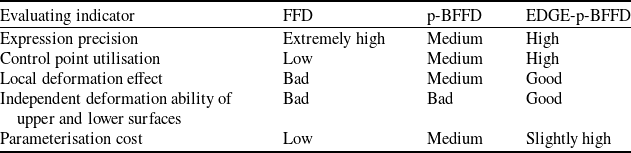
The differences between the EDGE-p-BFFD method and the p-BFFD method have been compared from three aspects: control point utilisation, the deformation effect, and the independence of upper and lower surface deformation. In order to make the comparison results clearer, a comparison table (see Table 5) is made, and the traditional FFD method is added to the comparison object. Parameterisation cost in the table refers to the computing resources consumed in parameter initialisation of objects.
According to the above, the EDGE-p-BFFD method based on double control body frames proposed in this paper is generally better than FFD and p-BFFD methods in the application of lifting body configuration. It can expand design space and save computing resources and more refined parametric representation and deformation operations are achieved. Maybe the only disadvantage is that the calculation cost of parameter initialisation is slightly higher, but it is still acceptable.
The above compares the difference between EDGE-p-BFFD and p-BFFD from three aspects, namely the utilisation rate of control points, the deformation effect and the independence of upper and lower surface deformation. The results show that the application effect of EDGE-p-BFFD method based on double control body frames in the lifting body configuration is much better than p-BFFD method. It can expand design space and save computing resources and more refined parametric representation and deformation operations are achieved.
Comparison of advantages and disadvantages of three parameterisation methods

6. Conclusion
Firstly, this paper systematically compares the characteristics of three common FFD basic functions at present which are then applied to the parametric modeling of a lifting body configuration. It is found that the classical FFD method based on Bernstein basic function has the highest expression accuracy, but its local deformation control ability is poor, and its deformation amplitude is the smallest under the same control point displacement. The BFFD method based on B-spline basic function needs to solve the special distribution of control points according to the specific configuration. Although its expression accuracy is less than that of the classical FFD method, it can still meet the modeling requirements. Besides, its local deformation control ability is very strong, and the deformation operation has the best following performance.
As for NURBS basic function, it is the most flexible in theory because the weight coefficient is introduced on the basis of control points and object point variables. NURBS basic function is often used in the current parameterisation improvement methods as well. In the case of parameterised fitting of three-dimensional lifting body configuration in this paper, a variety of optimisation algorithms have been tried, but no method to meet the accuracy requirements has been found. In other words, under the current optimisation system, it needs to take a long time to find the weight coefficient satisfying accuracy, which is unacceptable in the conceptual design stage of aircraft. On the other hand, the parametric fitting method by compromising the weight coefficient has certain uncertainty itself, because the weight coefficient also affects the control effect of the control points in the deformation. Thus, even if the weight coefficient that meets the accuracy requirement is found, the subsequent deformation control effect is worth further discussion and verification.
An inverse solution idea of parametric modeling is proposed in this paper, that is, the configuration and control points that can produce the deformation results are deduced by specifying control points and corresponding configurations, which makes the BFFD method more flexible and universal. This method can not only achieve good local expression and deformation control ability, but also change the position of control points according to the actual task requirements under the condition of ensuring the topology of control volume. So p-BFFD method can almost completely replace the FFD method of traditional Bernstein basic function in most cases, achieving better local control effect and deformation following ability. Moreover, the modeling of p-BFFD method is simpler than NFFD method, and the deformation control effect is more stable.
With the support of the reverse solution idea, this paper puts forward the EDGE-p-BFFD parameterisation method for the lifting body configuration. By putting the control points to the edge and interior of the lifting body, the edge of the lifting body is fixed, and the proportion of effective control points is significantly improved, and the deformation effect becomes more reasonable as well. In the case of this paper, the expression error of the proposed EDGE-p-BFFD parameterisation method is reduced from the original 1.01E-3 to 1.25E-4, thus the accuracy is improved nearly ten times. The ratio of effective control points is also increased from 36.7% to 50%. And the more control points, the more obvious the proportion improvement effect. Then an independent deformation method of the upper and lower surfaces based on the double control body frames is proposed. Two control bodies of the same scale are used to model the upper and lower surfaces of the lifting body, respectively, which effectively avoids the simultaneous manipulation of the upper and lower surfaces by a single control point.
The p-BFFD method proposed in this paper realises the free distribution of control points to a certain extent, and its flexibility is significantly improved. Therefore, it should also have more applicable fields. For example, according to the conclusion that the outermost control points only have control effect on the edge object points, some control points can be distributed on the surface of objects that need fixed constraints. Then, the original object point cloud can be inversely solved by p-BFFD to complete the parametric representation. In this way, keeping the outermost control points unchanged in the deformation operation can realise the constraint of the outer configuration unchanged. Ref. (Reference Shen, Huang and Yan47) has achieved a similar technical effect by using the traditional FFD method. EDGE-p-BFFD method proposed in this paper is an application example of p-BFFD method in the parametric modeling of lifting body. In the future, it is expected to achieve more applications and improvements of p-BFFD method for specific configurations and different modeling purposes. What’s more, although the fitting effect of NURBS in this study is not ideal, if the weight coefficient is specified in advance, it should also be able to apply the reverse solution idea to carry out parametric modeling. But a high-level understanding of NURBS coefficient  ${\boldsymbol{\omega} _{{\rm{ }}i}}$ is required for technicians, which may become another potential research direction in the future.
Acknowledgement
This work was supported by the Natural Science Foundation of Hunan Province, China (No. 2021JJ10045) and the National Natural Science Foundation of China (No. 11972368). Also, the authors thank the reviewers for their constructive recommendations.
Conflict of interest statement
The authors declare there is no conflict of interest regarding the publication of this paper.