I. INTRODUCTION
For small-scale materials and structures, Poisson’s ratio can be indirectly obtained by indentation methods, such as friction force microscopy,Reference Carpick, Ogletree and Salmeron1 contact-resonance atomic force microscopy,Reference Hurley and Turner2–Reference Reinstädtler, Kasai, Rabe, Bhushan and Arnold4 or multiaxial (or called multidimensional) nanocontact measurement technique.Reference Lucas, Hay and Oliver5–Reference Gao, Xu, Oliver and Pharr7 These methods are based on a simple relationship between the lateral/normal contact stiffnesses and Poisson’s ratio that is independent of Young’s modulus. For axisymmetric contacts in elastically isotropic materials, the normal elastic contact stiffness, S normal, is given by the Sneddon solution, and the lateral stiffness, S lateral, is given by the Mindlin solutionReference Johnson8

where A n is the normal contact area. The reduced moduli, E * and G *, are given by
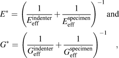
where the effective moduli of the contacting solid are given by E eff = E/(1 − ν 2) and G eff = G/(2 − ν), and E, G, and ν are the Young’s modulus, shear modulus, and Poisson’s ratio. Assuming that the indenter is rigid, the stiffness ratio measurement can then be used to measure the specimen’s Poisson’s ratio using

Experimental measurements for isotropic materials such as fused silica and glass agree well with the above prediction.Reference Hurley and Turner2, Reference Lucas, Hay and Oliver5
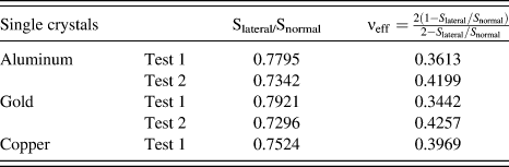
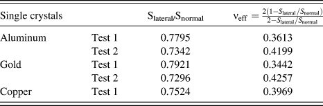
For elastically anisotropic materials, the situation is not nearly as simple. Using a multiaxial nanocontact system, Lucas et al.Reference Lucas, Hay and Oliver5 tested various materials and demonstrated that the stiffness ratio may depend on the direction in the surface that the material is tested, as shown in Table I. Although they claimed that their experimental data for several cubic crystals generally agree with the stiffness ratio derived from the bulk Poisson’s ratio, we believe that the experimental results should scatter considerably depending on the material anisotropy and may fall into a range whose bounds can be predicted from an anisotropic elastic contact analysis. In Section II, using an analytical method that is based on the Stroh formalism and the two-dimensional Fourier transform,Reference Gao and Pharr9 this work will systematically examine the dependence of an effective Poisson’s ratio (to be defined shortly) on the normal/lateral contact directions and crystal structures.
Measured lateral to normal contact stiffness ratios and the resulting effective Poisson’s ratios for representative single crystals.
It is also important to note that the Sneddon solution was derived for frictionless interface conditions, whereas the Mindlin solution assumes infinite friction so that the differences in elastic constants of indenter and specimen—or denoted as elastic dissimilarity—also become an issue. If the infinite friction condition is violated, the lateral contact stiffness may reduce to zero because of the development of an interface micro-slip zone.Reference Gao, Lucas, Hay, Oliver and Pharr6–Reference Johnson8 Experimental measurements are typically conducted by applying a small lateral oscillation on the contact, so interface micro-slip will not occur for sufficiently large contact sizes (e.g., >100 nm). The role of elastic dissimilarity is much more complicated to deal with analytically. To address this issue, we present the results of detailed finite element simulations in Section III that examine the accuracy of the predicted stiffness ratio in Eq. (1) for anisotropic solids. In addition, indentation tests are usually performed with three-sided pyramidal indenters so that the contact shape is noncircular—a condition that does not permit an analytical treatment as in Eq. (1). To this end, numerical simulations are performed to compare the effective indentation moduli of anisotropic solids for circular or triangular contacts in Section III. In Section IV, our analytical and numerical results are compared to experiments reported in literature using a multiaxial nanocontact system. Since the lateral contact stiffness can be measured using atomic friction microscopy-based tests, two issues of interest are discussed including a comparison of the lateral indentation modulus to the material shear modulus for transversely isotropic materials and the role of interface adhesion on the stiffness prediction. A summary of these results is given in Section V.
II. ANALYTICAL RESULTS FOR UNIAXIAL AND INDENTATION STRESS FIELDS
For an anisotropic solid under uniaxial loading, Poisson’s ratio is defined by
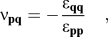
where ε pp and ε qq are normal strains in the p and q (orthonormal vectors) directions and the solid is subjected to a uniaxial stress in the p direction. The elastic constitutive law is εij = Sijklσkl, where Sijkl are the compliance constants. Using the tensor transformation,Reference Baughman, Shacklette, Zakhidov and Stafstroem10–Reference Lethbridge, Walton, Marmier, Smith and Evans13 the tensile modulus in direction p and the shear modulus and Poisson’s ratio in the plane spanned by p and q are given by E p = (Sijklpipjpkpl)−1,G pq = (4Sijklpiqjpkql)−1, and 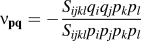 , where pi and qi are the components of the vectors. The factor of 4 appears in G pq due to the Voigt contracted notation for shear. For a cubic crystal, the simplified forms are



where Sij are the components of the elastic compliance tensor in Voigt contracted form.
Motivated by Eq. (3), we define the effective Poisson’s ratio for an anisotropic crystal under indentation loading as

where the normal contact direction is p and the tangential contact direction is q. Note that the indenter is assumed rigid. As discussed in Section I, if the specimen is elastically isotropic, Eqs. (4) and (6) would be identical. The difference of these two definitions for anisotropic materials is presented next.
Effective indentation moduli for anisotropic crystals can be computed by the Green’s function approach.Reference Gao and Pharr9, Reference Vlassak and Nix14, Reference Vlassak and Nix15 Consider a half-space single crystal with surface normal x 3 and in-plane directions xα, where the subscript α is either 1 or 2. We define the Green’s tensor w(x 1,x 2) as the surface deflection due to a unit point force vector, t0δ(x 1)δ(x 2), applied at the origin of the coordinate system so that surface deflection is  . Because the elasticity problem is governed by a set of partial differential equations which are homogeneous of degree 1, the Green’s function in Fourier space is homogeneous of degree −1 and is given by
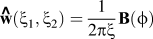 , where (ξ1,ξ2) is the wavevector,
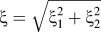 , and ϕ = tan−1 (ξ2/ξ1). The Stroh matrix B depends only on the elastic constants and ϕ and can be determined by a Stroh formalism-based representation.Reference Gao and Pharr9 In brief, an eigenvalue problem cijlmhjhmAl = 0 is solved, where h = [cosϕ,sinϕ,p]T, p is the eigenvalue, and Al is the eigenvector. Out of the six roots that form three pairs of complex conjugates, we choose the three with positive imaginary parts, pa (a = 1, 2, 3). The Stroh matrix is calculated by B = i AL−1 with
 (no summation convention implied over a). For circular contacts, the multiaxial contact moduli are then given by
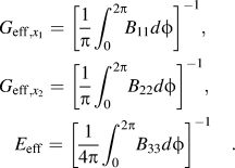
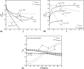
The normal indentation modulus has been extensively studied previously,Reference Gao and Pharr9, Reference Vlassak and Nix14, Reference Vlassak and Nix15 while here results are presented for arbitrary combinations of normal and lateral contact directions and also for both cubic crystals and transversely isotropic materials. Because of the sixth order polynomial involved in the Stroh formalism, a closed-form analytical solution can only be derived when x 3 and ϕ are along <001> directions for cubic crystals, but this will not be useful in reaching an analytical solution for the indentation moduli. Numerical results are presented in Fig. 1 for the two representations in Eqs. (5) and (6) for cubic crystals, where −0.5 < c 12/c 11 < 1 and the anisotropy factor is A = 2c 44/(c 11 − c 12). Because of symmetry, Poisson’s ratio is independent of q for the {100} and {111} surfaces. Thus, we plot  and
 against the anisotropy parameter A in Fig. 1(a) and Fig. 1(b), respectively. The difference between the two representations of Poisson’s ratio can be very large when the anisotropy parameter A is significantly different from unity. They are only the same for an isotropic material (i.e., A = 1). The discrete symbols on these two plots are for copper, aluminum, and gold single crystals with elastic constants obtained from Bower.Reference Bower16 Moreover, for the {110} surface, the effective Poisson’s ratio depends on the tangential contact direction q. For example, as shown in Fig. 1(c), the effective Poisson’s ratios for copper, aluminum, and gold single crystals decrease as q rotates from [110] to [001], but the uniaxial definition in Eq. (5) increases. The maximum effective Poisson’s ratio is
 , and the minimum effective Poisson’s ratio is
 .
For cubic crystals under normal indentations in (a) <100> and (b) <111> directions, the effective Poisson’s ratio is independent of the tangential direction and is therefore only a function of c 12 / c 11 and the anisotropy factor A=2c 44/(c 11 −c 12). The indentation effective Poisson’s ratios for Al, Au, and Cu are given as discrete symbols. (c) With surface normal  , when the tangential contact direction q rotates in-plane from [110] to [001] with rotation angle θ, the effective Poisson’s ratio displays a fourfold symmetry.

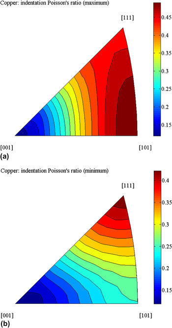
One question that naturally arises is what the upper and lower bounds of the effective Poisson’s ratio in Eq. (6) are for arbitrary p and q. Although the limits of Poisson’s ratio in Eq. (4) may be obtained analytically,Reference Ting and Barnett11, Reference Ting and Chen12 the extreme values of Eq. (6) must be numerically determined with the help of the stereographic triangle on the inverse pole figure. As shown in Fig. 2, because of cubic symmetry, the normal indentation direction, p, is taken to vary in the 〈001〉 unit triangle of the inverse pole figure. With a given surface normal, p, we vary the tangential direction q in the plane that is orthogonal to p, and thus determine the extreme values of Poisson’s ratio. These maximum and minimum effective Poisson’s ratios as a function of p are illustrated in the pole figures in Fig. 3. Values at the vertices are listed in Tables II–V. For all the single crystals considered (copper, aluminum, and gold; A > 1), the upper bound (i.e., the overall maximum Poisson’s ratio) is  and the lower bound (i.e., the overall minimum Poisson’s ratio) is
 .
For a copper surface with a given surface normal p, the maximum and minimum effective Poisson’s ratios can be determined as the tangential contact direction q rotates on the orthogonal plane. These extreme values are plotted against p as it varies in the 〈001〉 unit triangle of the inverse pole figure. At the [101] vertex, the maximum value is  and the minimum one is
 .

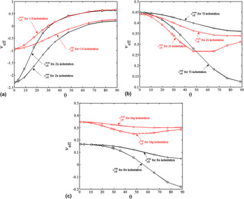
The effective Poisson’s ratio as a function of the zenith angle between the indentation direction and the c-axis of hexagonal closed-packed single crystals.

Effective contact moduli as obtained from Eq. (7) for copper, aluminum, and gold single crystals.

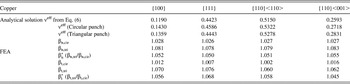
Predicted and simulated effective Poisson's ratios, as well as the stiffness correction factors, for copper single crystals with c 11 = 168.4 GPa, c 12 = 121.4 GPa, and c 44 = 75.4 GPa.

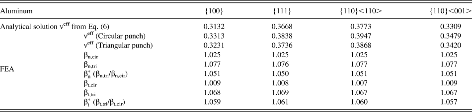
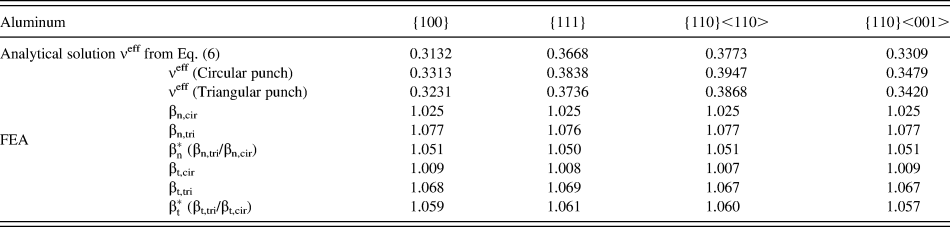
Predicted and simulated effective Poisson's ratios, as well as the stiffness correction factors, for aluminum single crystals with c 11 = 108.2 GPa, c 12 = 61.3 GPa, and c 44 = 28.5 GPa.
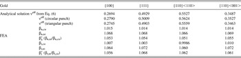
Predicted and simulated effective Poisson's rations, as well as the stiffness correction factors, for gold single crystals c 11 = 186 GPa, c 12 = 157 GPa, and c 44 = 42 GPa.

Scanning force microscopy tests often use transversely isotropic materials, for which the solutions greatly simplify. Let the third principal direction be the normal of the plane of transverse isotropy, thus c 66 = (c 11 − c 12)/2. Again, a general analytical solution of the Stroh eigenvalue problem is not possible unless the indentation direction is normal to the plane of transverse isotropy. Based on the derivations in the Appendix, the effective indentation moduli in this direction are
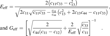
Eq. (8) can be used to construct the effective Poisson’s ratio in Eq. (6). The uniaxial definition in Eq. (4) now becomes 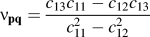 , where p is the normal direction of the transversely isotropic plane and q is arbitrary direction that is perpendicular to p. A straightforward calculation of several hexagonal closed-packed (hcp) materials shows a large difference between these two definitions. It is also noted that after some simplifications, the normal effective modulus in Eq. (8) agrees with the contact solution using the Green–Zerna stress potential method for transversely isotropic material.Reference Espinasse, Keer, Borodich, Yu and Wang17
Deviating from the above special case, the extreme values of the effective Poisson’s ratio are presented in Fig. 3 for several representative hcp single crystals. The indentation direction forms a zenith angle, θ, with the c-axis. For these materials, the minimum v eff with a given indentation direction is reached when the tangential direction is perpendicular to the plane spanned by the indentation direction and the c-axis. Shear in a 90° rotation from this direction will lead to the maximum v eff. It has been documented both analytically and experimentally that the uniaxial Poisson’s ratio can be negative and does not appear to be bounded.Reference Baughman, Shacklette, Zakhidov and Stafstroem10–Reference Lethbridge, Walton, Marmier, Smith and Evans13 Our numerical tests for both cubic and hcp crystals (Figs. 1 and 3) indicate that the effective Poisson’s ratio can also be negative.
III. FINITE ELEMENT SIMULATIONS OF FRICTION AND CONTACT SHAPE EFFECTS
The Sneddon solution assumes no friction between the contacting surfaces so that additional interface shear stress is needed to meet the infinite friction condition. JohnsonReference Johnson8 has summarized the solution for the normal contact under infinite friction condition but no counterparts exist for anisotropic solids, lateral contacts, or noncircular contacts. As noted in the introduction, the Mindlin solution for lateral contact is limited to elastically isotropic solids and indenters that have identical elastic properties (or more precisely, elastically similar materials) with no slip at the contact surface.Reference Johnson8 Since the anisotropic contact analysis also suffers from this limitation, it is necessary to modify the solutions in Eq. (1) with correction factors, β n and β t, that account for the effects of modulus mismatch and contact shape.Reference Gao, Xu, Oliver and Pharr18–Reference Lee, Kim and Lee21 They are defined by
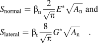
In Tables III–VI, β n,cir and β t,cir are the normal and tangential correction factors for a flat-ended circular punch and β n,tri and β t,tri are those for a flat-ended triangular punch.
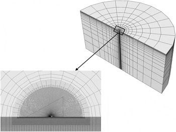
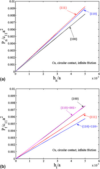
An arbitrary contact problem can be regarded as a superposition, in incremental fashion, of a flat-ended punch contact problem, which also gives the contact stiffness.Reference Gao and Pharr9, Reference Gao, Xu, Oliver and Pharr18 Therefore, to evaluate the effects of elastic dissimilarity, friction, and contact shape on the effective Poisson’s ratio, finite element analyses (FEA) were performed for flat-ended circular and triangular punch contacts. These rigid punches are indented on representative surfaces of cubic and hcp single crystals with frictionless or infinite friction conditions. Because of symmetry, only half of the elastic substrate was meshed, with a typical mesh having 97,161 elements, as shown in Fig. 4. The rigid punch moves vertically down to establish the normal contact, and subsequently it moves laterally in the direction parallel to the symmetry plane and normal to one of the triangular contact edges. Representative load–displacement curves for copper single crystals under infinite friction condition are given in Fig. 5, where P n and P t are normal and tangential loads, and h n and h t are normal and tangential displacements, respectively. The normal and lateral stiffness values are obtained from the indentation load–displacement curves, and thus the effective Poisson’s ratios are calculated. The mesh sensitivity was carefully studied previously so that accurate stiffness and indentation responses can be obtained.Reference Lee, Lee and Pharr19–Reference Lee, Kim and Lee21
The three-dimensional finite element model for the flat-ended triangular punch contact. The applied lateral force is parallel to the symmetry plane and perpendicular to the triangular edge.

Representative (a) normal and (b) tangential load–displacement curves with a being the radius of the circular flat-ended punch. For lateral contact, a test on the {100} surface with arbitrary lateral direction collapses onto that on the {110} surface with <001> lateral direction.

For frictionless normal circular contact, our finite element results agree well with the analytical predictions in Eq. (7) without the need of the correction factor; numerical error is usually less than 1%. For a triangular punch under the frictionless condition, the correction factor, β n,tri, is about 1.06, which is a consequence of contact shape. The correction factors β n,cir and β n,tri for infinite friction are about 1.03 and 1.08, and therefore the shape factor,  , defined as the ratio of β n,tri to β n,cir, is about 1.05. For copper, aluminum, and gold single crystals, the effective Poisson’s ratios and correction factors obtained from the normal and tangential contact FEA results are compared in Tables III–V, and results for zinc and titanium single crystals under indentation along the c-axis are given in Table VI. In these simulations, infinite friction coefficient was assumed. In these tables,
 means the ratio of β t,tri to β t,cir. The shape factors are all about 1.05–1.07 irrespective of the contact direction.
Predicted and simulated effective Poisson’s ratios, as well as the stiffness correction factors for circular and triangular contacts, are obtained for indentation onto the plane of transverse isotropy (i.e., indentation along the c-axis) for the hexagonal closed-packed single crystals.

For Zn, c 11 = 161 GPa, c 12 = 34.2 GPa, c 13 = 50.1 GPa, c 33 = 61 GPa, and c 44 = 38.3 GPa. For Ti, c 11 = 162.4 GPa, c 12 = 92 GPa, c 13 = 69 GPa, c 33 = 180.7 GPa, and c 44 = 46.7 GPa.Reference Bower16
Our numerical simulations are restricted to flat-ended punch contacts. The correction factors for the pyramidal indentation into elastic–plastic solids are much more complicated because of the complicated contact area/shape, pile-up and sink-in, and inelastic deformation. However, a triangular flat-ended punch can be used to mimic the unloading process of a three-sided pyramidal indentation. Based on the shape factors documented in Tables III–VI and our previous finite element simulations of elastic–plastic spherical indentation,Reference Gao, Xu, Oliver and Pharr18 it is anticipated that the analytical solutions in Eq. (7) are generally valid, and the effects of elastic dissimilarity and contact shape are small (∼5% difference for effective indentation moduli and 5–10% for the effective Poisson’s ratio).
IV. DISCUSSION
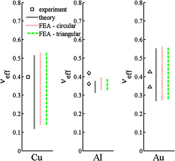
The predicted effective Poisson’s ratios in Tables III–V (all for cubic crystals with A > 1) can be compared to the multiaxial nanocontact experiments.Reference Lucas, Hay and Oliver5 Since the surface orientations were not characterized in these experiments, we can only examine the predicted bounds. As shown in Fig. 6, the copper and gold single crystals fall within the bounds but the experimental results for aluminum are slightly larger than the prediction, which might be due to the presence of an oxide layer on the surface. Figure 6 also illustrates how a single crystal with a large degree of elastic anisotropy (e.g., copper) will have a wide range of effective Poisson’s ratio, whereas that with a small degree of elastic anisotropy (e.g., aluminum) will have a narrow range of variation. It should be noted that these measurement data are taken at large indentation depths (>100 nm), where the lateral contact response is ensured to be elastic. At small indentation depths, interface friction will reduce the stiffness ratio dramatically, and in this case, the stiffness ratio reduction can be used to probe the friction anisotropy.Reference Annett, Gao, Cross, Herbert and Lucas22

Tests on fused silica using contact-resonance atomic force microscopyReference Hurley and Turner2 and multiaxial nanocontact methodReference Lucas, Hay and Oliver5 both confirm the validity of the Mindlin solution. For anisotropic materials, the effective shear modulus G eff is usually estimated as G/(2−v) using the bulk shear modulus and bulk Poisson’s ratio or by c 44 for both cubic and hcp single crystals. These estimates can be radically different from our analytical predictions. For instance, for graphite (c 11 = 1060 GPa, c 12 = 180 GPa, c 13 = 15 GPa, c 33 = 37 GPa, and c 44 = 0.35 GPa), the closed-form solution in Eq. (8) gives G eff = 7.54 GPa, which is about 20 times larger than c 44. An accurate calculation of G eff is critical in the evaluation of friction properties using friction force microscopy.Reference Carpick, Ogletree and Salmeron1 In this technique, the friction force F fric is assumed to be τ fricA n with the interface friction stress τ fric; thus, from Eq. (1), one can obtain τ fric from the measurements of  and G eff.
Another practical problem for application of the above experimental techniques in nanocontacts involves the influence of interface adhesion. The JKR adhesive contact solution can be constructed by superposing a Hertizan contact and a flat-ended contact,Reference Johnson8, Reference Espinasse, Keer, Borodich, Yu and Wang17 giving the following contact pressure distribution:

where r is the radial coordinate and a is the contact radius. The Hertizan component is p 0 = 2aE * / πR with R being the indenter radius. The second term in Eq. (10) is a crack solution, and the interface adhesion requires that the energy release rate at the contact edge be equal to 2γ, with γ being the surface energy, leading to  . This representation clearly works for transversely isotropic contact using the closed-form equation in Eq. (8). However, it does not work even for the {100} surface of a cubic crystal because the energy release rate of the flat-ended circular contact punch solution depends on the local Stroh matrix at the contact edge and in general is not a constant unless the indentation plane is of transverse isotropy. One may adopt the solution for a noncircular flat-ended punch contact since a constant energy release rate may be obtained if the contact shape is carefully chosen. But this will lead to a surface distortion that may not permit an analytical solution of the elastic contact [i.e., the first term in Eq. (10)]. Despite the fact that the elastically anisotropic adhesive contact generally leads to a noncircular contact shape without analytical solution, the indentation moduli can still be predicted based on Eq. (7) because the shape effect is usually small, as shown in Section III.
V. SUMMARY
For elastically isotropic solids, Poisson’s ratio has a simple relationship to the lateral to normal contact stiffness ratio in Eq. (3). For elastically anisotropic solids, the effective Poisson’s ratio defined in Eq. (6), which can be derived by the Green’s function approach, depends on both the normal and tangential contact directions. The difference between the effective Poisson’s ratio and the uniaxial definition generally follows the trends given in Figs. 1–3, and the exact magnitude of the difference can be very large. Analytical solutions of the indentation moduli can only be established for materials having at least one plane of transverse isotropy. Theoretical predictions for a variety of crystals and loading directions are in a good agreement with those obtained from FEA with flat-ended punches. Although the experiments were conducted using a Berkovich triangular pyramid indenter, it is anticipated that the effects of the resulting correction factors with respect to indentation direction are small since the contact shape in this case is close to triangular shape. Implications are also discussed for the experimental measurements by multiaxial nanocontact system and atomic force microscopy based technique.
ACKNOWLEDGMENTS
The authors are grateful to National Science Foundation CMMI 0800168 for financial support and to B.N. Lucas, W.C. Oliver, D.C. Hurley, and R.F. Cook for helpful discussions on their experimental work.
APPENDIX: EFFECTIVE INDENTATION MODULI FOR TRANSVERSELY ISOTROPIC MATERIALS
The analytical solution of the Stroh eigenvalue problem is generally not feasible because of the sixth order polynomial. Here, we consider a transversely isotropic material with an indentation direction along the normal of the plane of transverse isotropy, which leads to the following relationship:

Thus, the effective indentation moduli can be derived from Eq. (7) as

The eigenvalue problem can be analytically solved for ϕ = 0°, giving

Therefore, 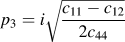 and
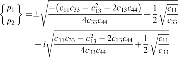
if  (e.g., for Zn, Cd, and Be), or

if  (e.g., for Ti, Cr, and Mg). The following calculations involve tedious algebraic derivations, leading to
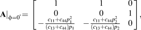
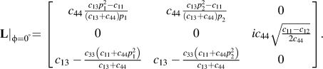
Although other choices of matrices A and L can be made, the Stroh matrix is unique. Its analytical representation, combined with Eq. (A2), gives rise to the analytical solutions in Eq. (8).