1. Introduction
1.1. Literature review
During the last two decades, parallel robots have become more ubiquitous, employed in a great variety of sectors, namely, food [Reference Clavel1], medical [2], aerospace [3, Reference Starrag Group Holding4] and agricultural [5]. Due to the modularity of their kinematic chains, the actuators can be installed at or near the fixed base, reducing the inertia of their mechanical structure. As a consequence, parallel robots are much more efficient than their serial counterparts in terms of performing fast motions and consuming less energy [Reference Tsai6–Reference Briot and Bonev8].
Concerning the control, the followed direction [Reference Hesselbach, Pietsch, Bier and Becker9–Reference Choi, Konno and Uchiyama11] has been to adapt the mature control techniques, already employed in most of serial robots, into the parallel ones. With respect to the decentralized control, the input signal for the control of an individual joint relies on the measurement of the related joint displacement and velocity [Reference Chung, Fu, Hsu, Siciliano and Khatib12]. According to Chung et al. [Reference Chung, Fu, Hsu, Siciliano and Khatib12], the decentralized control, such as the PID compensator, is appropriate in set-point regulation tasks. However, in operations that demand the capability of trajectory tracking and high speed, the PID performance is not satisfactory. In such cases, the centralized control, based on the robot dynamic model, considering the interaction between the active joints, can provide better results [Reference Hesselbach, Pietsch, Bier and Becker9].
Among the investigated centralized control strategies, the Computed Torque techniques are certainly relevant due to the fact they convert a system, originally non-linear and coupled regarding the input and output variables, into a linear and decoupled closed-loop system. [Reference Chung, Fu, Hsu, Siciliano and Khatib12, Reference Craig13] To succeed on applying such technique, one has to keep the model uncertainties under limited boundaries. [Reference Slotine14] Among those, one can mention parameter uncertainties, load variations, model simplifications, friction, clearances and elastic deformations. [Reference Hesselbach, Pietsch, Bier and Becker9, Reference Zhan, Zhang, Jian and Zhang15, Reference Grzelczyk16]
For parallel robots, some critical factors play a significant role. First, the complexity of the complete inverse dynamics model [Reference Zubizarreta, Cabanes, Marcos and Pinto17, Reference Singh and Santhakumar18], characterized by the presence of a huge number of terms, may cause the infeasibility of the real-time control once their calculation is a compute-intensive task. In fact, this is a direct consequence of their mechanical structure due to the presence of more than a single kinematic chain and, consequently, moving bodies. Second, once the control is usually performed in the joint space, the path tracking error increases considerably mainly because of the existence of joint clearances, link deformations or even vibrations. On the other hand, the control in the task space has been employed; [Reference Ozgur, Andreff and Martinet19, Reference Li and Xu20] however, there are precision and cost limitations on the current available sensors to determine the end-effector location [Reference Mohan21].
In order to overcome such drawbacks, some works propose the Computed Torque control in a feed-forward mode [Reference Choi, Company, Pierrot, Konno, Shibukawa and Uchiyama10, Reference Wang, Wu, Wang, Liu and Yu22, Reference Lipiski23] because it allows the model computation out of the control loop. Moreover, others recommend the utilization of either robust or even adaptive control strategies [Reference Safonov24–Reference Natal, Chemori and Pierrot31] which have demonstrated promising results for parallel robots [Reference Hesselbach, Pietsch, Bier and Becker9, Reference Singh and Santhakumar18, Reference Achili, Daachi, Amirat, Ali-Cherif and Dachi26, Reference Zeinali and Notash32, Reference Sarkar33]. Among the robust approaches, the Sliding Mode (SM) control can deal with system model inaccuracies, parametric uncertainties and external disturbances [Reference Long, Du, Wang and Dong34]. The SM control drives the state trajectory to a predefined sliding surface by using discontinuous control inputs and retains it there [Reference Mahmoodabadi, Taherkhorsandi, Talebipour and Castillo-Villar35]. However, this technique also shows some drawbacks, namely, chattering [Reference Lee, Choi and Kim36, Reference Li, Ghasemi, Xie and Gao37], long settling time [Reference Lee, Choi and Kim36], non-smooth control input [Reference Mahmoodabadi, Taherkhorsandi, Talebipour and Castillo-Villar35] and low tracking performance [Reference Truong, Tran and Ahn38].
In order to overcome the limitations of each control technique and keep its own benefits, the hybrid control, that is, the combination of distinct control techniques, has been proposed. Many works recommend the combination of SM with PD control [Reference Mahmoodabadi, Taherkhorsandi, Talebipour and Castillo-Villar35–Reference Li, Ghasemi, Xie and Gao37, Reference Acob, Pano and Ouyang39–Reference Kara and Mary41]. As a result, the achievements are chattering reduction, shorter settling time, smoother control input [Reference Mahmoodabadi, Taherkhorsandi, Talebipour and Castillo-Villar35, Reference Li, Ghasemi, Xie and Gao37] and model free approach [Reference Acob, Pano and Ouyang39–Reference Kara and Mary41]. Alternatively, Truong et al. [Reference Truong, Tran and Ahn38] propose the combination of SM with a neural network in order to achieve higher tracking performance. Lin and Wai [Reference Lin and Wai42] studied the combination of the Computed Torque control and the fuzzy neural network in a 1-dof planar mechanism. On the other hand, the hybridization of the Computed Torque and Sliding Mode controls was investigated by Yu [Reference Yu43] and Peng et al. [Reference Peng, Wang and Wang44] in 2-dof planar mechanisms. Furthermore, most of the published papers show only simulations, see for example refs. [Reference Singh and Santhakumar18–Reference Li and Xu20, Reference Lipiski23, Reference Mahmoodabadi, Taherkhorsandi, Talebipour and Castillo-Villar35, Reference Lee, Choi and Kim36, Reference Acob, Pano and Ouyang39–Reference Kara and Mary41, Reference Yu43–Reference Wen, Hu, Zhang, Sheng, Lam and Zhao47] and few experimental result. [Reference Sarkar33, Reference Li, Ghasemi, Xie and Gao37, Reference Truong, Tran and Ahn38, Reference Lin and Wai42, Reference Li48–Reference Zhang, Fang and Zou50]
1.2. Objectives
This paper presents a comparison of the performance of hybrid control techniques with the pure ones in parallel robots. Basically, the authors propose the combination of a modified Sliding Mode technique with other conventional ones, namely, the PD and the Computed Torque controls. In order to validate the theoretical predictions and evaluate their behaviour in terms of the end-effector path control in transient and steady states, experimental tests in a planar parallel robot are conducted. Moreover, simulations are also conducted to evaluate the behaviour of a 3-dof spatial parallel robot, when performing a 3D-path. The evaluation of the performance is done by computing the root-mean-square values of the path tracking error and actuator torques during the entire motion cycle.
1.3. About the paper sections
Section 2 deals with the theoretical foundations for the combination of distinct control techniques, while Section 3 presents a detailed description of the experimental setup and the obtained experimental results. Section 4 treats the performance of the hybrid controls from a conducted simulation of a spatial parallel robot. Finally, Section 5 addresses a discussion, and the main conclusions are drawn in Section 6.
2. Proposed Hybrid Control Law and Stability Analysis
The dynamic model of a mechanical system can be described by the following equation [Reference Craig13, Reference Khalil and Dombre51]
 \begin{equation}\textbf{H}(\textbf{q}) \, \ddot{\textbf{q}} + \textbf{h}(\textbf{q},\dot{\textbf{q}}) = \textbf{u}\end{equation}
where
 $\textbf{q}$
is the vector of the generalized and independent coordinates,
 $\textbf{H}(\textbf{q})$
is the inertia matrix,
 $\textbf{h}(\textbf{q},\dot{\textbf{q}})$
is the vector of the centrifugal, Coriolis, gravitational and friction terms, while
 $\textbf{u}$
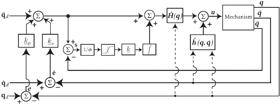
is the control effort. Here, the control law for the proposed hybrid controls (Figure 1) is given by
Block diagram of the proposed hybrid controls.

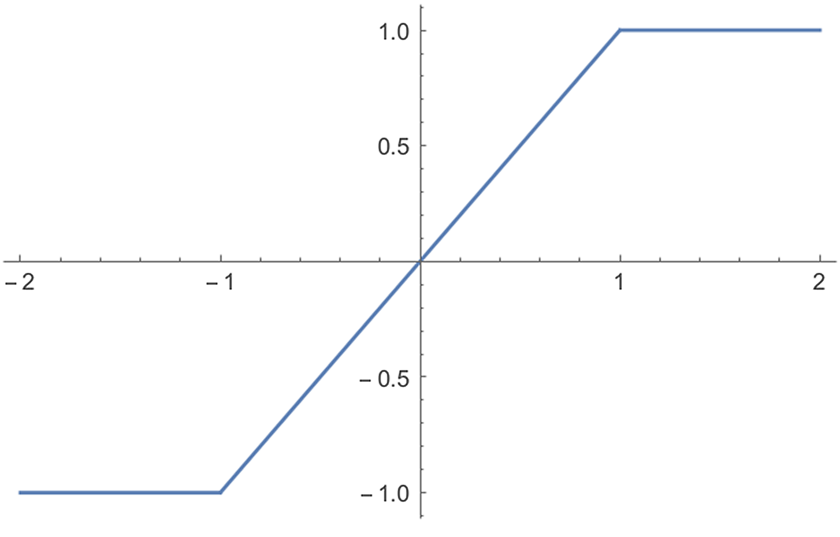
Plot of the function
 $\textrm{sat}(x)$
.

 \begin{equation}\textbf{u} = \hat{\textbf{H}}(\textbf{q}) \left(\ddot{\textbf{q}}_d + \underline{k}_v \,\dot{\textbf{e}} + \underline{k}_p \, \textbf{e} + \int_0^t {\underline{k}\, \textrm{sat}(\textbf{s} / \boldsymbol{\phi}) \, d\tau}\right) + \hat{\textbf{h}}(\textbf{q},\dot{\textbf{q}})\end{equation}
where
 $\textbf{q}_d$
is the reference signal,
 $\textbf{e}$
is the error signal, defined by
 $\textbf{e} = \textbf{q}_d - \textbf{q}$
,
 $\hat{\textbf{H}}(\textbf{q})$
and
 $\hat{\textbf{h}}(\textbf{q},\dot{\textbf{q}})$
are estimations of
 $\textbf{H}(\textbf{q})$
and
 $\textbf{h}(\textbf{q},\dot{\textbf{q}})$
, respectively, and
 $\underline{k}_v$
,
 $\underline{k}_p$
and
 $\underline{k}$
are positive definite diagonal matrices. Additionally, the variable
 $\textbf{s}$
is defined as
 \begin{equation}\textbf{s}=\ddot{\textbf{e}} + \underline{k}_v \,\dot{\textbf{e}} + \underline{k}_p \, \textbf{e}\end{equation}
The vector division used in the expression
 $\textrm{sat}(\textbf{s} / \boldsymbol{\phi})$
is defined as the division term by term, while Eq. (4) defines the saturation function (Figure 2)
 \begin{equation}\textrm{sat}(x) = \begin{cases}x, \;\;\;\;\;\;\;\;\; |x| < 1 \\[3pt] \textrm{sgn}(x), \; |x| \geq 1\end{cases}\end{equation}
The parameter vector
 $\boldsymbol{\phi}$
means the thickness of the boundary layer defined in a small vicinity with respect to the sliding surface. The purpose of the saturation function is to smooth the control discontinuity of the signum function and reduce chattering. [Reference Li, Ghasemi, Xie and Gao37, Reference Acob, Pano and Ouyang39, Reference Kara and Mary41, Reference Qi, McInroy and Jafari52] Note that for
 $\underline{k} = \textbf{0}$
, the control law becomes the Computed Torque control law. Since the term
 $\int_0^t {\underline{k}\, \textrm{sat}(\textbf{s} / \boldsymbol{\phi}) \, d\tau}$
comes from the Sliding Mode control [Reference Islam and Liu25, Reference Piltan and Sulaiman27, Reference Mahmoodabadi, Taherkhorsandi, Talebipour and Castillo-Villar35], the control law can be considered hybrid.
2.1. Stability analysis
Theorem 1. (refs. [Reference Suttirak and Pukdeboon53, Reference Chen, Yang, Zhang and Liu54]) Consider a non-linear system
 $\dot{\textbf{x}}(t) = \textbf{f}(\textbf{x},t)$
, where
 $\textbf{x} \in \mathbb{R}^n$
,
 $\textbf{x}(0) = \textbf{x}_0$
is the initial state, and the origin
 $\textbf{x} = \textbf{0}$
is the equilibrium point. Suppose there are two real numbers
 $\rho > 0$
,
 $0 < \beta < 1$
, and a continuously differentiable positive function
 $V:\mathbb{R}^n \to \mathbb{R}$
, such that the inequality
 \begin{equation}\dot{V}(\textbf{x}) + \rho {V(\textbf{x}) }^\beta \leq 0\end{equation}
is always fulfilled for any solution
 $\textbf{x}(t,\textbf{x}_0)$
of the system. Then, the equilibrium point is globally finite-time stable. In addition, the settling time
 $t_s$
, which depends on the initial state, satisfies the following inequality
 \[t_s \leq \frac{1}{(1-\beta) \, \rho } \, V(\textbf{x}_0)^{1-\beta} = t^*\]
Proof. Assuming that
 ${\textbf{x}} \neq \textbf{0}$
, inequality (5) can be divided by
 $V^\beta$
,
 \begin{equation}{V}^{-\beta} \, \frac{dV}{dt} + \rho \leq 0\end{equation}
Integrating (6) with respect to time from 0 to t,
 \begin{align}&\int_{V(\textbf{x}_0)}^{V(\textbf{x})} V^{-\beta} dV + \int_{0}^t \rho \, d\tau \leq 0 \nonumber\\[3pt] &\quad \frac{V^{1-\beta}}{1-\beta} {\Bigg|}_{V(\textbf{x}_0)}^{V(\textbf{x})} + \rho \, (t-0) \leq 0\nonumber\\[3pt] &\quad V(\textbf{x})^{1-\beta} \leq V(\textbf{x}_0)^{1-\beta} - (1-\beta) \, \rho \, t\end{align}
Notice that the right side of inequality (7), which corresponds to the upper bound of
 $V(\textbf{x})^{1-\beta}$
, decreases linearly as t increases its value and becomes negative for
 $t > t^*$
. On the other hand, by definition, since
 $V(\textbf{x})$
is continuous and positive, the lower bound of
 $V(\textbf{x})^{1-\beta}$
is zero. Considering that inequality (7) is only valid for
 $\textbf{x} \neq 0$
; hence,
 $V(\textbf{x})^{1-\beta}$
converges to zero and, consequently, V as well, in a finite time lesser or equal
 $t^*$
and, therefore, the system is globally finite-time stable.
Replacing the control effort
 $\textbf{u}$
(Eq. (2)) in Eq. (1) and subtracting
 $\hat{\textbf{H}} \, \ddot{\textbf{q}} + \hat{\textbf{h}}$
in both sides,
 \begin{equation}\textbf{H} \, \ddot{\textbf{q}} + \textbf{h} - \hat{\textbf{H}} \, \ddot{\textbf{q}} -\hat{\textbf{h}} = \hat{\textbf{H}} \left(\ddot{\textbf{q}}_d + \underline{k}_v\dot{\textbf{e}} + \underline{k}_p \textbf{e} + \int_0^t { \underline{k} \, \textrm{sat}(\textbf{s} / \boldsymbol{\phi}) \, d\tau}\right) + \hat{\textbf{h}} -\hat{\textbf{H}}\,\ddot{\textbf{q}} - \hat{\textbf{h}}\end{equation}
Since
 $\textbf{e}=\textbf{q}_d-\textbf{q}$
, and defining
 $\tilde{\textbf{H}} =\textbf{H}-\hat{\textbf{H}}$
and
 $\tilde{\textbf{h}} = \textbf{h}-\hat{\textbf{h}}$
 \begin{equation}\tilde{\textbf{H}} \, \ddot{\textbf{q}} + \tilde{\textbf{h}} = \hat{\textbf{H}} \bigg(\ddot{\textbf{e}} + \underline{k}_v\dot{\textbf{e}} + \underline{k}_p \textbf{e} + \int_0^t {\underline{k}\, \textrm{sat}(\textbf{s} / \boldsymbol{\phi}) \, d\tau} \bigg)\end{equation}
Hence,
 \begin{equation}\tilde{\textbf{H}} \, \ddot{\textbf{q}} + \tilde{\textbf{h}} = \hat{\textbf{H}} \left(\textbf{s}+\int_0^t{\underline{k}\, \textrm{sat}(\textbf{s} / \boldsymbol{\phi}) \, d\tau}\right)\end{equation}
Multiplying both sides from the left by
 $\hat{\textbf{H}}^{-1}$
, the following expression is obtained
 \begin{equation}\textbf{s}+\int_0^t {\underline{k}\, \textrm{sat}(\textbf{s} / \boldsymbol{\phi}) \, d\tau} = \boldsymbol{\epsilon}\end{equation}
where
 \begin{equation}\boldsymbol{\epsilon} = \hat{\textbf{H}}^{-1} (\tilde{\textbf{H}} \, \ddot{\textbf{q}} + \tilde{\textbf{h}})\end{equation}
In addition, differentiating Eq. (11) with respect to time
 \begin{equation}\dot{\textbf{s}} + \underline{k} \, \textrm{sat}(\textbf{s} / \boldsymbol{\phi}) = \dot{\boldsymbol{\epsilon}}\end{equation}
Since
 $\underline{k}$
is a diagonal matrix, there is no coupling between the components of
 $\textbf{s}$
and the dynamics of each component of
 $\textbf{s}$
can be written as
 \begin{equation}\dot{s}_i + k_i \, \textrm{sat}(s_i / \phi_i) = \dot{\epsilon}_i\end{equation}
Furthermore, consider the Lyapunov candidate function
 $V_i(s_i)$
, expressed as
 \begin{equation}V_i(s_i) = \frac{1}{2} \, s_i^2 \geq 0\end{equation}
Differentiating
 $V_i(s_i)$
with respect to time
 \begin{equation}\frac{\mathsf{d}}{\mathsf{d} t} \big( V_i(s_i) \big) = s_i \dot{s}_i\end{equation}
Isolating
 $\dot s_i$
in Eq. (14) and replacing it in the previous equation
 \begin{equation}\dot{V}_i = s_i \,(\dot{\epsilon}_i - k_i \, \textrm{sat} (s_i/\phi_i))\end{equation}
In addition,
 $s_i$
and
 $\textrm{sat}(s_i / \phi_i)$
can be replaced by
 $|s_i| \, \textrm{sgn}(s_i)$
and
 $\textrm{sat}(|s_i| / \phi_i)) \,\textrm{sgn}(s_i)$
, respectively,
 \begin{equation}\begin{split}\dot{V}_i &= |s_i| \, \textrm{sgn}(s_i) \,(\dot{\epsilon}_i - k_i \, \textrm{sat}(|s_i|/\phi_i) \textrm{sgn}(s_i) ) \\[3pt] &= |s_i| \, (\dot{\epsilon}_i \, \textrm{sgn}(s_i) - k_i \, \textrm{sat}(|s_i|/\phi_i) )\end{split}\end{equation}
Assuming there are no modelling errors, then
 \begin{equation}\boldsymbol{\epsilon} = \textbf{0} \Rightarrow \dot{\boldsymbol{\epsilon}} = \textbf{0}\end{equation}
 \begin{equation}\therefore \dot{V}_i(s_i) = - k_i \, |s_i| \, \textrm{sat}(|s_i| / \phi_i) < 0 {, s_i \neq 0}\end{equation}
Even though this assumption is not very realistic, it is commonly used in the proof of stability of control laws, like the Computed Torque Control. On the other hand, when there are modelling errors (
 $\boldsymbol{\epsilon} \neq \textbf{0}$
), some further analysis can be conducted. Assuming that the system is outside the boundary layer, which means that
 $|s_i| \geq \phi_i$
Eq. (18) can be written as
 \begin{equation}\begin{split}\dot{V}_i(s_i) &= |s_i| \, (\dot\epsilon_i \textrm{sgn}(s_i) - k_i) \\[3pt]&{\,\,\leq |s_i| \, (|\dot\epsilon_i| - k_i)}\end{split}\end{equation}
Additionally, since
 $\dot{\epsilon}_i$
is bounded (assuming the system never assume configurations where
 $\hat{\textbf{H}}$
is singular), it is possible to select a positive number
 $\delta_i$
[Reference Qi, McInroy and Jafari52–Reference Chen, Yang, Zhang and Liu54] that satisfies the condition
 $|\dot{\epsilon}_i| \leq \delta_i$
. Hence, choosing a value for
 $k_i$
such that
 $k_i > \delta_i$
:
 \begin{equation*}\dot{V}_i \leq |s_i| \, (|\dot\epsilon_i| - k_i) \leq |s_i| \,(\delta_i - k_i) \leq 0\end{equation*}
Also, note that
 $|s_i|$
equals to
 $\sqrt{2 V_i}$
. Hence,
 \[\dot{V}_i \leq - \sqrt{2 V_i} \, (k_i - \delta_i) \leq - \sqrt{2} \, (k_i - \delta_i) \, {V_i}^{1/2}\]
 \begin{equation}\therefore \dot{V_i} + \sqrt{2} \, (k_i - \delta_i) \, {V_i}^{1/2} \leq 0\end{equation}
Notice that inequality (22) falls into the same category of inequality (5) of Theorem 1, where
 $\rho = \sqrt{2} \, (k_i \, - \, \delta_i) > 0$
and
 $\beta = 1/2$
. Therefore, in the limit case where there is no boundary layer (
 $\phi_i \rightarrow 0$
and
 $\textrm{sat}(s_i/\phi_i) \rightarrow \textrm{sgn}(s_i)$
), the proposed hybrid control law makes the equilibrium point
 $s_i = 0$
globally finite-time stable. Also, after reaching the sliding surface
 $s_i = 0$
, the error signal
 $e_i$
will decrease exponentially to zero, since
 $s_i = \ddot{e}_i + k_{v_i}\dot{e}_i + k_{p_i}e_i$
. In this limit case, the reaching time to the sliding surface satisfies the following inequality,
 \[t_{s\,i} \leq \frac{\sqrt{2}}{ (k_i - \delta_i) } \, V_i\, (s_i(0))^{1/2} = {t_i}^{*}\]
Additionally, for an arbitrary value of
 $\phi_i$
, one can affirm that the variable
 $s_i$
will reach the boundary layer
 $|s_i| \leq \phi_i$
in a finite time equals or lesser than
 ${t_i}^*$
and, consequently,
 $|e_i|$
will also be bounded for
 $t \geq {t_i}^*$
. According to the theory of linear control [Reference Craig13, Reference Khalil and Dombre51], the damping ratio of the second-order system
 $\ddot{e}_i + k_{v_i}\dot{e}_i + k_{p_i}e_i = s_i$
is given by
 $\zeta = \frac{k_{v_i}}{2\sqrt{k_{p_i}}}$
. Since there is no overshoot nor resonance for
 $\zeta \geq 1$
and the DC gain of the system is
 $1/k_{p_i}$
, one can conclude that for
 $k_{v_i} \geq 2\sqrt{k_{p_i}}$
, the upper bound of
 $|e_i|$
becomes
 $\phi_i/k_{p_i}$
.
3. Experiments
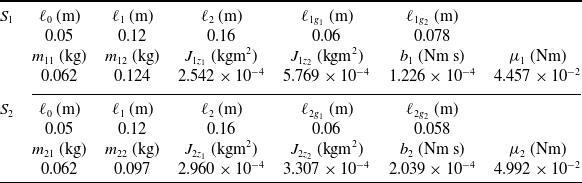
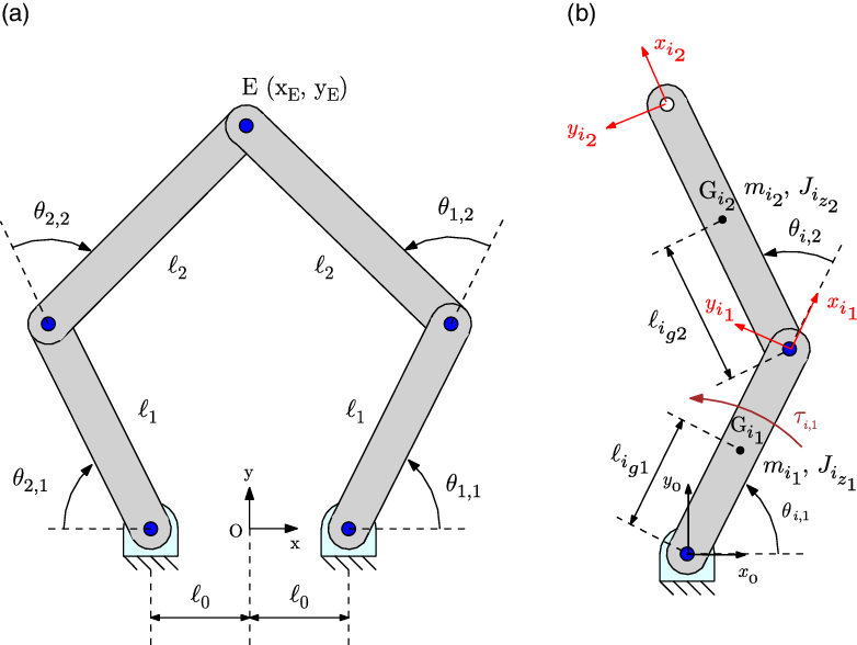
The experimental tests focus on applying hybrid control techniques to a parallel robot. The chosen parallel robot has three subsystems, namely, mechanical, actuation and control. Regarding the mechanical subsystem, it is composed of a 2-dof planar parallel mechanism [Reference Acob, Pano and Ouyang39, Reference Acob40, Reference Coutinho, Bartholomeu, Stevanni, Oliveira-Fuess, Hess-Coelho and Colon49], commonly known as 5R mechanism (Fig. 3(a)), which has four moving links and one fixed one, all connected by revolute joints. The dimensional parameters are the lengths
 $l_0$
,
 $l_1$
,
 $l_2$
,
 $l_{i_{g_1}}$
,
 $l_{i_{g_2}}$
, while the inertial parameters are the masses
 $m_{i1}$
,
 $m_{i2}$
, and the mass moments of inertia
 $J_{i_{z_1}}$
,
 $J_{i_{z_2}}$
with respect to the centre of mass of each moving link that belongs to the kinematic chain
 $S_i$
(Fig. 3). Additionally,
 $b_i$
and
 $\mu_i$
are, respectively, the viscous and dry friction coefficients at the actuated revolute joints.
3.1. Control strategies
For comparison purposes, the following control laws have been defined for use in the experiment, all in the joint space:
-
Proportional Derivative with acceleration feed-forward (PD)
(23) \begin{equation}\textbf{u} = \underline{m}^* ( \ddot{\textbf{q}}_d + \underline{k}_v \dot{\textbf{e}} + \underline{k}_p \textbf{e} )\end{equation}
-
Proportional Derivative with acceleration feed-forward + Sliding Mode (PD+SM)
(24)
\begin{equation}\textbf{u} = \underline{m}^* \Big( \ddot{\textbf{q}}_d + \underline{k}_v \dot{\textbf{e}} + \underline{k}_p \textbf{e} + \int_0^t \underline{k} \textrm{sat}(\textbf{s} / \boldsymbol{\phi}) \mathsf{d} \tau \Big)\end{equation}
-
Computed Torque (CT)
(25)
\begin{equation}\textbf{u} = \hat{\textbf{H}}(\textbf{q}) \, ( \ddot{\textbf{q}}_d + \underline{k}_v \dot{\textbf{e}} + \underline{k}_p \textbf{e} ) + \hat{\textbf{h}}(\textbf{q}, \dot{\textbf{q}})\end{equation}
-
Computed Torque + Sliding Mode (CT+SM)
(26)
\begin{equation}\textbf{u} = \hat{\textbf{H}}(\textbf{q}) \, \Big( \ddot{\textbf{q}}_d + \underline{k}_v \dot{\textbf{e}} + \underline{k}_p \textbf{e} + \int_0^t \underline{k} \textrm{sat} (\textbf{s} / \boldsymbol{\phi}) \mathsf{d} \tau \Big) + \hat{\textbf{h}}(\textbf{q}, \dot{\textbf{q}})\end{equation}


For the PD and PD+SM controls, the constant diagonal matrix
 $\underline{m}^*$
replaces the inertia matrix
 $\hat{\textbf{H}}$
. The elements of
 $\underline{m}^*$
are obtained from the elements of the diagonal of
 $\hat{\textbf{H}}$
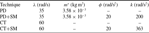
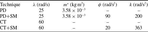
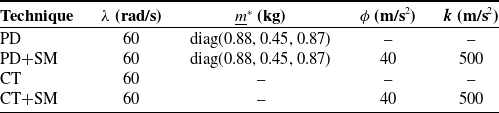
at a central configuration with respect to the robot workspace and are available in Table II. Additionally, for both controls, the term
 $ \hat{\textbf{h}} = \textbf{0} $
. In the CT+SM control law, the full dynamic model presented in Appendix A is used to calculate the estimations of
 $\hat{\textbf{H}} $
and
 $\hat{\textbf{h}}$
. Note that CT and PD control laws can be generated by making
 $ \underline{k} = 0 $
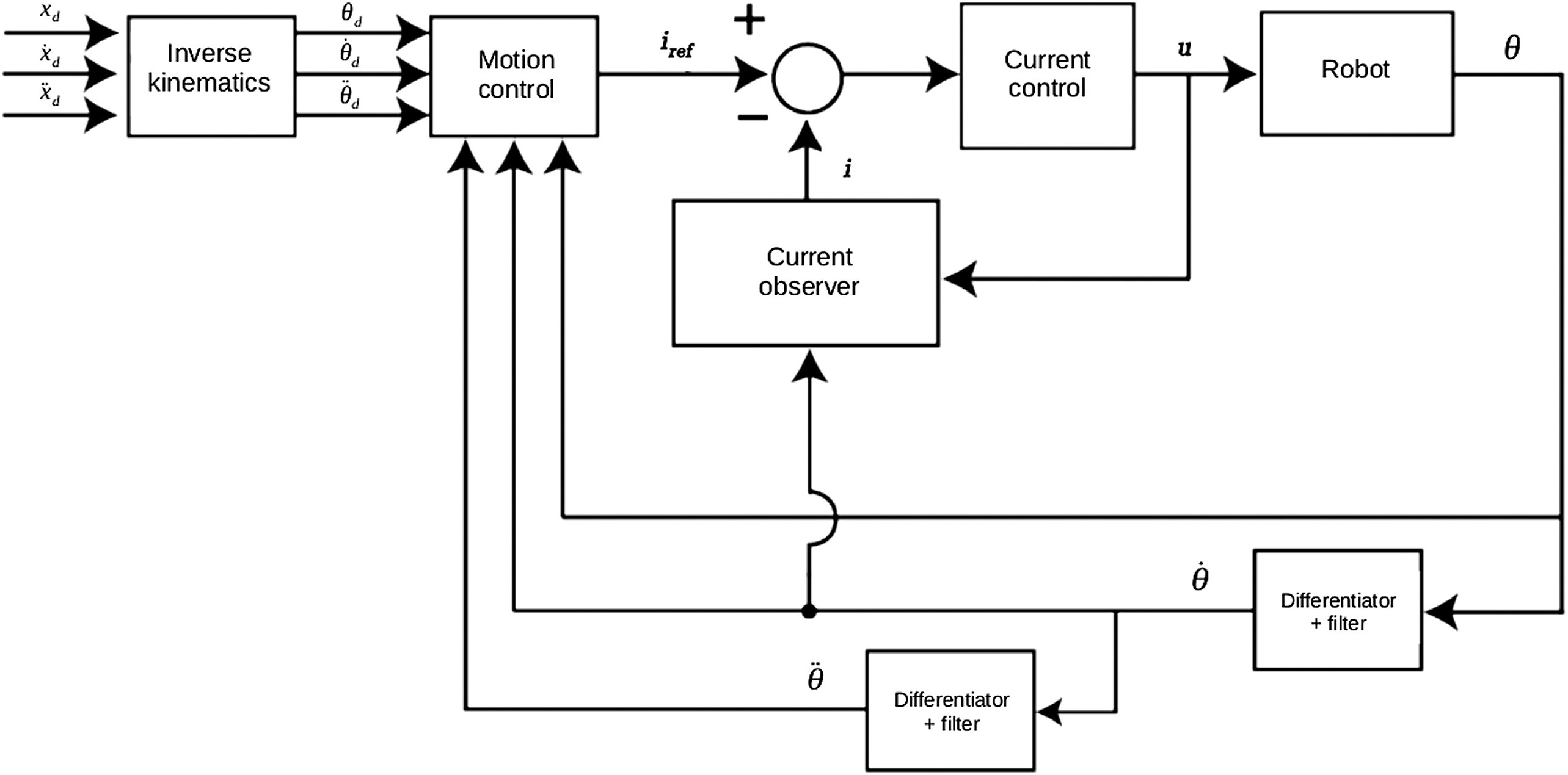
in CT+SM and PD+SM laws, respectively. Figure 4 shows the block diagram of the overall control loop in the joint space.
Dimensional and inertial parameters of the chains
 $S_i$
of the mechanism.

Controller parameters for the circular path.

(a) 5R parallel mechanism; (b) a RR kinematic chain
 $S_i$
.

The block diagram of the overall control loop in the joint space.

In order to estimate, for instance, the angular velocities of the actuator shafts from the angular displacement measurements provided by the encoders, the numerical differentiation is implemented by applying the finite difference method. Aiming to avoid the amplification of high-frequency noise of the acquired signal due to the use of finite difference technique, the numerical differentiations are employed in series with two types of filters. For the velocity estimation from the position measurements, a second-order Bessel low-pass filter is used, while for the acceleration estimation from the velocity computation, an eight-order Bessel low-pass filter is employed [Reference Thompson55].
3.2. Experimental test-bed
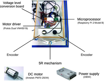
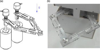
Figure 5 shows the components of the robot systems. Constructively, the mechanical system (Fig. 6) has five revolute joints which correspond to rigid ball bearings. For the moving links, flat bars made of aluminium alloy and acrylic are employed. In addition, once the motion plane is horizontal, the dynamic model does not take into account the gravitational forces [Reference Coutinho, Bartholomeu, Stevanni, Oliveira-Fuess, Hess-Coelho and Colon49].
The components of the robot systems.

The mechanical system: (a) CAD model; (b) 5R mechanism.

Regarding the actuation system, it is composed of two direct drive DC motors (250 W each) AMETEK PM70, one motor driver Pololu Dual VNH5019, and a switched-mode power supply (24V, 390 W).
The control system has two incremental rotary encoders E40S (5000 quad-counts per turn) and one microprocessor Raspberry Pi 2 model B. Additionally, there is an electronic circuit board for the conversions of the voltage levels, from the power supply to the encoder (24–15V), and from the encoders to the microprocessor (0–15V to 0–3.3V).
3.3. Paths
The centre coordinates (0;158 mm) and the radius 50 mm define the circular path, which the end-effector performs it clockwise with constant tangential velocity. Additionally, the duration of one cycle of the path is 1 s. In each test, the total acquisition time for measuring the experimental data comprises 8 cycles. After the 8 cycles, the reference signal is fixed in its last position, forcing a sudden stop.
The triangular path is defined by three vertices, which are (
 $-2\,\textrm{mm}$
;108 mm), (50 mm;258 mm) and (
 $-50\,\textrm{mm}$
;258 mm) and is performed counterclockwise. Moreover, the end-effector takes 0.75 s to go from one vertex to the other, whose kinematic variables are interpolated by a seventh-order polynomial. Regarding the conditions to determinate the polynomial coefficients, they are the initial and final coordinates of the end-effector. Moreover, the velocities, accelerations and jerks are all null at the vertices of each side of the triangular path. In each test, the total acquisition time for measuring the experimental data comprises 2 cycles. Additionally, in both paths, the end-effector starts from the position (
 $-2\,\textrm{mm}$
;108 mm).
3.4. Controller gains
In order to impose the same dynamics in both components of the control error and critical damping at the closed-loop system poles, the matrices
 $\underline{k}_p$
,
 $\underline{k}_v$
,
 $\underline{k}$
,
 $\underline{m}^*$
and the vector
 $\boldsymbol{\phi}$
are parametrized as follows,
 \begin{equation}\underline{k}_p = \lambda^2 \textbf{1}\end{equation}
 \begin{equation}\underline{k}_v = 2 \lambda \textbf{1}\end{equation}
 \begin{equation}\underline{k} = k \textbf{1}\end{equation}
 \begin{equation} \underline{m}^* = m^* \textbf{1}\end{equation}
 \begin{equation}\boldsymbol{\phi} = \phi \begin{bmatrix}1 & 1\end{bmatrix}^T\end{equation}
where
 $\textbf{1}$
is the identity matrix.
The controller parameters for each technique and prescribed path are shown in Tables II and III. The parameter
 $\lambda$
corresponds to the desired natural frequency of the closed-loop system poles.
3.5. Experimental results
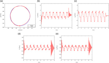
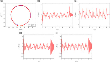
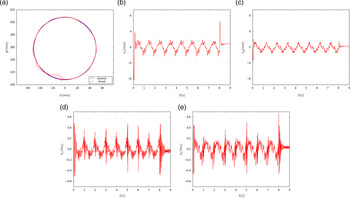
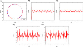
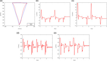
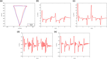
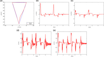
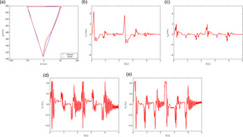
The experimental results comprise a comparison between the desired and actual paths, the path tracking errors in the x- and y-directions, and the actuator torques. For the circular path, the plots for the PD, PD+SM, CT and CT+SM are shown in Figs. 7, 8, 9 and 10, respectively. For the triangular path, the plots for the PD, PD+SM, CT and CT+SM are shown in Figs. 11, 12, 13 and 14, respectively.
Controller parameters for the triangular path.

Pure PD control: circular path. (a) Desired and actual circular paths. (b) x-direction control error. (c) y-direction control error. (d) Torque of actuator 1. (e) Torque of actuator 2.

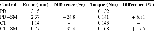
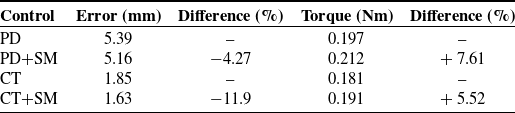
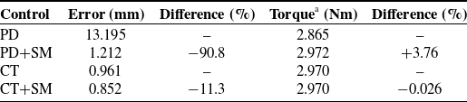
Tables IV and V show the metrics for the circular and triangular paths, respectively. In the second column of these tables, the term error means the root-mean-square value of the path tracking error of the defined path during the entire motion cycle. Similarly, in the fourth column, the term torque means the root-mean-square value of a composition of the actuator torques related to the path during the correspondent cycle. Regarding the term difference, that appears in the third and fifth columns of Tables IV and V, it means the relative percent difference between the considered metrics values of the pure control and the hybrid control, assuming the pure control as the reference value.
Hybrid PD+SM control: circular path. (a) Desired and actual circular paths. (b) x-direction control error. (c) y-direction control error. (d) Torque of actuator 1. (e) Torque of actuator 2.

Pure CT control: circular path. (a) Desired and actual circular paths. (b) x-direction control error. (c) y-direction control error. (d) Torque of actuator 1. (e) Torque of actuator 2.

Hybrid CT+SM control: circular path. (a) Desired and actual circular paths. (b) x-direction control error. (c) y-direction control error. (d) Torque of actuator 1. (e) Torque of actuator 2.

Pure PD control: triangular path. (a) Desired and actual circular paths. (b) x-direction control error. (c) y-direction control error. (d) Torque of actuator 1. (e) Torque of actuator 2.

Hybrid PD+SM control: triangular path. (a) Desired and actual circular paths. (b) x-direction control error. (c) y-direction control error. (d) Torque of actuator 1. (e) Torque of actuator 2.

Pure CT control: triangular path. (a) Desired and actual circular paths. (b) x-direction control error. (c) y-direction control error. (d) Torque of actuator 1. (e) Torque of actuator 2.

Metrics for the circular path.

From those tables, one can observe that the hybrid controls cause a reduction of the path tracking error in both paths. On the other hand, the hybrid controls are responsible for the increase of the actuator torques in the analysed paths. Additionally, a model-based hybrid control shows better results for the path tracking error than a hybrid control that is not based on a model. For the triangular path, not only the model-based hybrid control improves the performance of the robot in terms of the path tracking error but also with respect to the actuator torques, in a comparison with the non-model-based one.
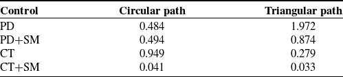
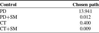
Table VI presents the steady-state error for the two analysed paths. The CT+SM is the control technique that has the best performance with lower errors in both paths. Despite the fact that the Computed Torque control does not demonstrate a good steady-state error performance in the circular path, for the triangular path, the CT control shows lower error values in comparison with the PD and PD+SM controls.
Metrics for the triangular path.

Steady-state error (mm) for the two paths.

Hybrid CT+SM control: triangular path. (a) Desired and actual circular paths. (b) x-direction control error. (c) y-direction control error. (d) Torque of actuator 1. (e) Torque of actuator 2.

4. Simulations
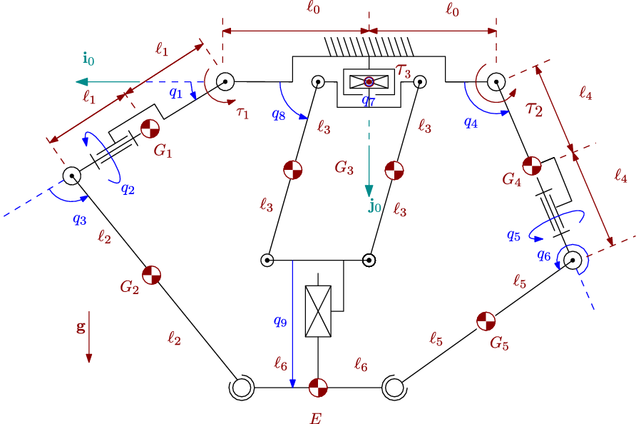
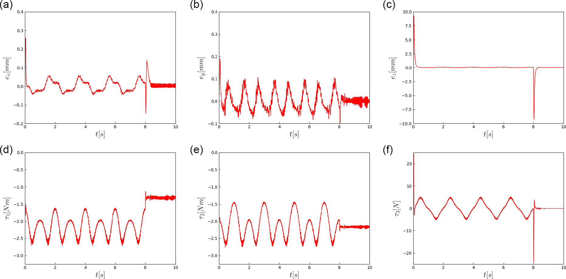
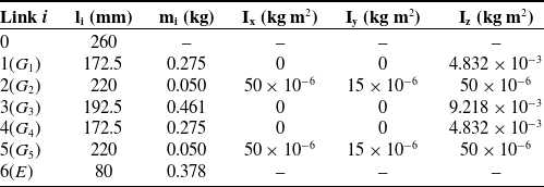
In order to evaluate the effectiveness of the proposed hybrid controls in a spatial parallel robot, the 2RRRS+P(Pa)P is selected as the mechanical structure. It consists of a topologically asymmetric parallel robot whose end-effector is able to perform three linear and independent displacements. The robot has three active kinematic chains, two of them are identical RRRS, while the other remaining is P(Pa)P. The letters R, P, S and Pa of the literal notation stand for revolute, prismatic, spherical and parallelogram joints, respectively. Particularly, the underlined ones correspond to the active joints. In Appendix B, Fig. B.1 shows the mechanism structure diagram, the employed variables, the parameters, the centres of mass and the actuator torques and force. In addition, the reader can also find in Table B.1 the selected parameters for the simulations. Furthermore, the full dynamic model is available in ref. [Reference Hess-Coelho, Orsino and Malvezzi57]. Regarding the chosen path, the coordinates of the end-effector with respect to time are defined as follows,
 \[{\left[ \begin{array}{c}x_E (t) \\ \\[-7pt] y_E (t) \\ \\[-7pt] z_E (t)\end{array} \right] =\left[ \begin{array}{c}- 180 \, \cos(\omega t) \\ \\[-7pt]400 - 30 \, \cos(\omega t) \\ \\[-7pt]180 \, \sin(\omega t) \\ \\[-7pt]\end{array} \right] \,\, {\rm (mm)} \qquad \qquad 0 \leq t \leq 4\,T }\]
where
 $T=2s$
and
 $\omega=2\pi/T$
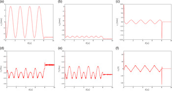
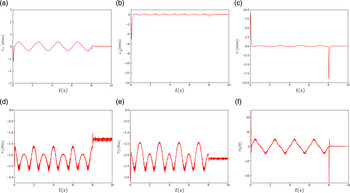
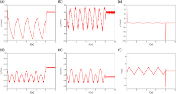
. In each simulation, the total time comprises four cycles. After 4 cycles, the reference signal is fixed in its last position, forcing a sudden stop. Moreover, an uncertainty level of 10% is assumed for the inertial parameters. The simulation results present a comparison between the path tracking errors in the x-, y- and z- directions, and the actuator torques. For the chosen path, the plots for the PD, PD+SM, CT and CT+SM are shown in Figs. B.2, B.3, B.4 and B.5, respectively (Appendix B).
Additionally, Table VII shows the controller parameters, while Tables VIII and IX present the obtained metrics and the steady-state errors for the chosen path. The reader can notice that the hybrid controls significantly reduce both the path tracking and steady-state errors with respect to the pure control laws, without producing a relevant increase of the actuator torques.
Controller parameters for the chosen path.

Metrics for the chosen path.

aFor the actuator 3, the torque is computed by assuming a pulley-timing belt transmission, with a pitch radius of 25 mm.
Steady-state error (mm) for the chosen path.

5. Discussion
There are some relevant issues that need a further discussion. First, as stated before, many proposed hybrid control laws, when applied to robotic manipulators, are based on the combination of PD and Sliding Mode controls. This paper verifies experimentally the benefits of such technique, and the obtained results shows the improvement of the robot performance. On the other hand, the other tested hybrid technique, the CT+SM, demonstrates a greater performance than the PD+SM in both analysed paths.
Therefore, the model-based hybrid technique brings more benefits to the robot behaviour than the hybrid technique that is not based on its model. Furthermore, in both tested hybrid techniques, the SM was modified by adding an integration block in the control loop which effectively reduced the chattering. Moreover, another significant contribution is that this paper provides an experimental validation of the two hybrid control techniques in fast motions.
The second issue concerns on the chosen paths. The circular path is a smoother trajectory once it keeps the same angular velocity during each cycle. Hence, the robot has a continuous behaviour in a steady-state mode. On the other hand, the triangular path is a more severe trajectory, characterized by sharp curves. Then, it is possible to evaluate the robot behaviour in a transient state mode, when the robot gripper has to move from one triangle vertex to another.
Third, regarding the steady-state error, it measures the capability for reaching end positions with a certain level of precision, a requirement in pick-and-place tasks. Concerning this metric, the CT+SM hybrid technique has demonstrated an outstanding performance. With respect to the path tracking error, the other index utilized here, it constitutes a requirement in tasks such as the milling processes.
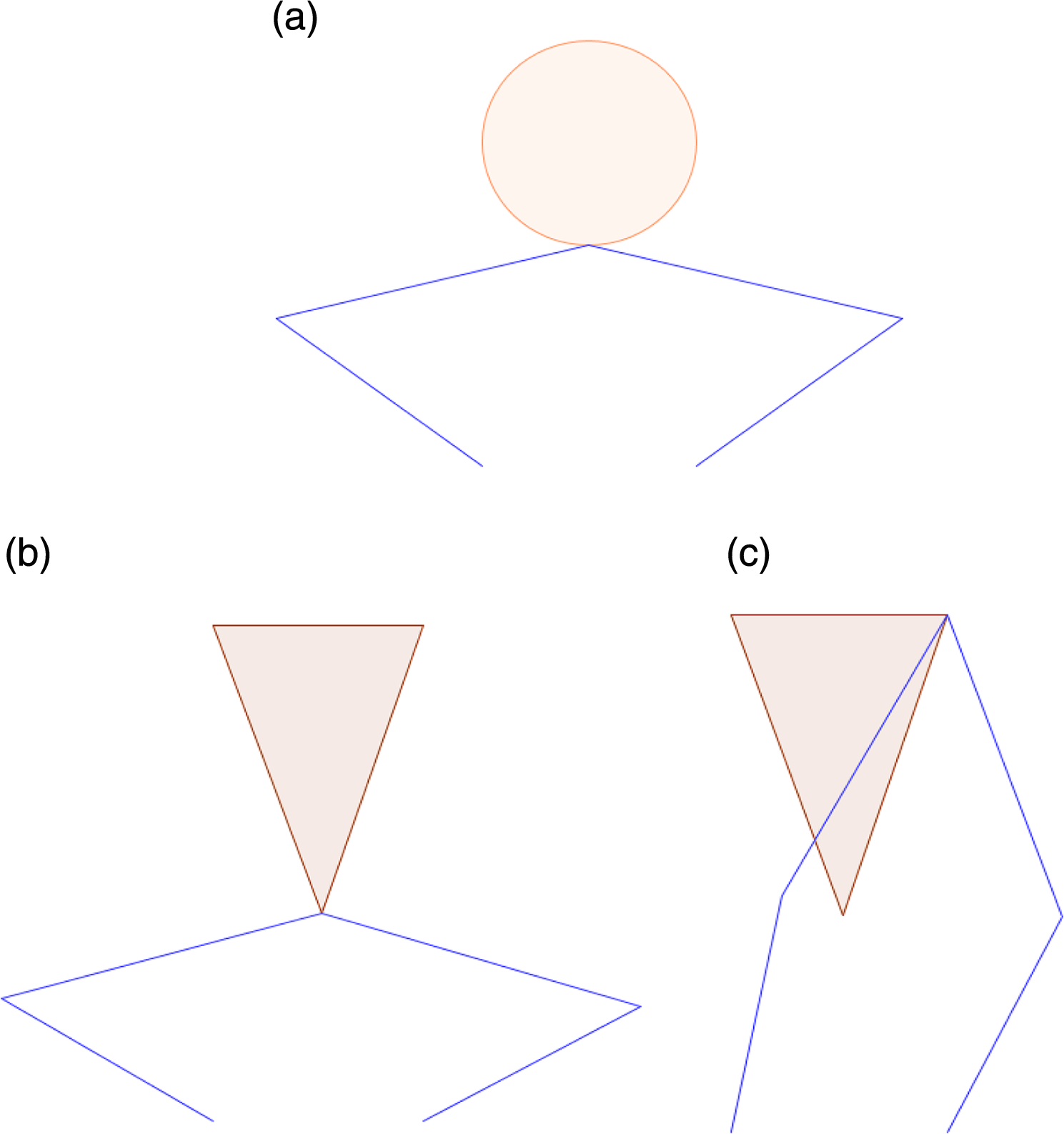
Fourth, one can observe higher tracking error in the initial configurations. For both tested paths, these errors appear only in the initial phase of the path, which might be due to static friction. For the circular path, after a while, the tracking error reduces significantly and even when it reaches that configuration in the next cycles. According to Fig. 15(a), such configuration is near an internal (type II) singularity. For the triangular path, the effect happens due to the fact that the initial configuration is the same (Fig. 15(b)). For the other triangle vertices, despite the proximity of a boundary (type I) singularity (Fig. 15(c)), low errors are observed. Hence, in spite of the proximity of singularities, the robot behaviour is stable in all control techniques evaluated.
(a) Circular path: initial configuration; (b) Triangular path: initial configuration; (c) Triangular path: configuration in the triangle vertex.

Figures 7–8 show the results for the circular path when applying the pure PD and PD+SM controls, respectively. During the eight cycles, the end-effector point rotates at the same angular speed. After those cycles, the reference signal is fixed in its last position, forcing a sudden stop. The sudden stop acts as an impulsive function, and it excites all the modes of vibration of the robot structure. As the reader can notice, this behaviour does not occur for the triangular path when applying the same controls (Figs. 11–12) once the path is interpolated by a seventh-degree polynomial.
6. Conclusions
6.1. Main contributions
This paper presented two novel hybrid control laws in order to improve the dynamic behaviour of parallel robots when performing fast motion tasks. The first hybrid control resulted from the combination of a pure PD control with a modified Sliding Mode control. The second hybrid control, in its turn, combined a pure Computed Torque with the altered Sliding Mode control. The proposed modifications in the Sliding Mode control aimed to achieve a considerable reduction of the tracking errors and chattering.
In order to reveal the performance of the hybrid controls in comparison with the pure ones, experiments were conducted in a 2-dof planar parallel robot, whose end-effector performed two distinct paths. Additionally, simulations were carried out to evaluate the behaviour of a 3-dof spatial parallel robot, when performing a 3D-path.
Both the experiments and the simulations evidenced that not only the path tracking errors are significantly reduced but also the steady-state errors as well, keeping the system stability even in the proximity of singularities. In addition, the authors remark that such achievements only caused a small increase of the actuator torques with very low chattering.
Finally, the authors emphasize the feasibility of the hybrid control based on the robot model, which could be implemented in real time, and still revealed a superior behaviour in a comparison with the hybrid control not based on the robot model.
6.2. Future works
To investigate the effectiveness of hybrid techniques in redundant parallel robots, that operate in planar and three-dimensional spaces.
Acknowledgements
The authors declare no competing interests. They acknowledge grant #162502/2015-0, Conselho Nacional de Desenvolvimento Científico e Tecnológico (CNPq). The authors are also very grateful to Guilherme Scabin Vicinansa for his valuable remarks regarding the finite-time stability proof of the control law.
Supplementary Material
To view supplementary material for this article, please visit https://doi.org/10.1017/S0263574721000874.
Appendix A. Dynamic model of a 2-dof planar mechanism 5R
The development of the dynamic model of a 2-dof planar 5R mechanism (Fig. 3) follows the approach of the Modular Modelling Methodology [Reference Orsino and Hess-Coelho56, Reference Hess-Coelho, Orsino and Malvezzi57]. Consider the i-th kinematic chain of the parallel mechanism, composed of the links 1 and 2. The unit vectors of the frame attached to the first link are
 \[{}^0\textbf{i}_{i_1} = \cos \theta_{i,1} \textbf{i}_0 + \sin \theta_{i,1} \, \textbf{j}_0\]
 \[{}^0\textbf{j}_{i_1} = -\sin \theta_{i,1} \textbf{i}_0 + \cos \theta_{i,1} \, \textbf{j}_0\qquad \qquad{}^0\textbf{k}_{i_1} = \textbf{k}_0\]
The vectors of the angular velocity of link 1 and the velocity of the centre of mass
 $G_1$
are, respectively,
 \[\boldsymbol{\omega}_{i,1} = \dot{\theta}_{i,1} \, \textbf{k}_{i_1} = \omega_{i,1} \textbf{k}_{i_1}\qquad \qquad\textbf{v}_{G_{i_1}} = \omega_{i,1} \, \ell_{i_{g1}} \,\, \textbf{j}_{i_1}\]
Those vectors can be rewritten as follows,
 \[\textbf{v}_{G_{i_1}} = V_{i_1} \, \boldsymbol{\omega}_i\qquad \qquad{\omega}_{i,1} = \Omega_{i_1} \, \boldsymbol{\omega}_i\]
where
 \[\boldsymbol{\omega}_i = [ \omega_{i,1}, \, \omega_{i,2} ]^T\qquad V_{i_1} = \left[ \begin{array}{cc}\dfrac{\partial \textbf{v}_{G_{i_1}}}{\partial \omega_{i,1}} & \frac{\partial \textbf{v}_{G_{i_1}}}{\partial \omega_{i,2}}\end{array} \right]\qquad\Omega_{i_1} = \left[ \begin{array}{cc}\frac{\partial \boldsymbol{\omega}_{i,1}}{\partial \omega_{i,1}} & \dfrac{\partial \boldsymbol{\omega}_{i,1}}{\partial \omega_{i,2}}\end{array} \right]\]
Hence,
 \[V_{i_1} = \left[ \begin{array}{cc}\ell_{i_{g1}} \, \textbf{j}_{i_1} & \textbf{0}\end{array} \right] = \left[ \begin{array}{cc} 0 & {0} \\ \ell_{i_{g1}} & {0} \end{array} \right]\qquad \qquad\Omega_{i_1} = \left[ \begin{array}{cc}1 & {\,\, 0}\end{array} \right]\]
Moreover, the inertia forces of the first link can be calculated as follows,
 \[m_{i_1} \textbf{a}_{G_{i_1}} = m_{i_1} (\dot{V}_{i_1} \boldsymbol{\omega}_i + V_{i_1} \, \boldsymbol{\dot{\omega}}_i)\qquad \qquad J_{i_{z1}} \, \dot{\omega}_{i,1} = J_{i_{z1}} \, \Omega_{i_1} \, \boldsymbol{\dot{\omega}}_i\]
where
 \[\dot{V}_{i_1} = \left[ \begin{array}{c@{\quad}c}-\ell_{i_{g1}} \omega_{i,1} \, \textbf{i}_{i_1} & \textbf{0}\end{array} \right] =\left[ \begin{array}{c@{\quad}c} - \ell_{i_{g1}} \omega_{i,1} & {0} \\ \\[-7pt] 0 & {0} \end{array} \right]\]
The unit vectors of the frame attached to the second link are
 \[{}^0\textbf{i}_{i_2} = \cos (\theta_{i,1}+\theta_{i,2}) \textbf{i}_0 + \sin (\theta_{i,1}+\theta_{i,2}) \textbf{j}_0\]
 \[{}^0\textbf{j}_{i_2} = -\sin (\theta_{i,1}+\theta_{i,2}) \textbf{i}_0 + \cos (\theta_{i,1}+\theta_{i,2}) \textbf{j}_0\qquad \qquad{}^0\textbf{k}_{i_2} = \textbf{k}_0\]
The vectors of the angular velocity of link 2 and the velocity of the centre of mass
 $G_2$
are, respectively,
 \[\boldsymbol{\omega}_{i,2} = (\dot{\theta}_{i,1}+\dot{\theta}_{i,2}) \, \textbf{k}_{i_2} = \omega_{i,2} \, \textbf{k}_{i_2}\qquad \qquad\textbf{v}_{G_{i_2}} = \omega_{i,1} (\ell_1) \, \textbf{j}_{i_1} +\omega_{i,2} \ell_{i_{g2}} \, \textbf{j}_{i_2}\]
Those vectors can be rewritten as follows,
 \[\textbf{v}_{G_{i_2}} = V_{i_2} \, \boldsymbol{\omega}_i\qquad \qquad{\omega}_{i,2} = \Omega_{i_2} \, \boldsymbol{\omega}_i\]
where
 \[V_{i_2} = \left[ \begin{array}{c@{\quad}c}\ell_1 \, \textbf{j}_{i_1} & \,\, \ell_{i_{g2}} \, \textbf{j}_{i_2}\end{array} \right] =\left[ \begin{array}{c@{\quad}c}\ell_1 {}^2R_1 \, {}^1\textbf{j}_{i_1} & \,\, \ell_{i_{g2}} {}^2\textbf{j}_{i_2}\end{array} \right]\qquad \qquad\Omega_{i_2} = \left[ \begin{array}{c@{\quad}c}0 & {\,\,1}\end{array} \right]\]
 \[{}^2R_1 = \left[\begin{array}{c@{\quad}c}\cos\theta_{i,2} & \,\, \sin\theta_{i,2} \\ \\[-7pt] -\sin\theta_{i,2} & \,\, \cos\theta_{i,2}\end{array}\right]\]
Hence,
 \[V_{i_2} =\left[ \begin{array}{c@{\quad}c}\ell_1 \, \sin\theta_{i,2} & \,\,0 \\ \\[-7pt] \ell_1 \, \cos\theta_{i,2} & \,\, \ell_{i_{g2}}\end{array} \right]\]
Moreover, the inertia forces of the second link can be calculated as follows,
 \[m_{i_2} \textbf{a}_{G_{i_2}} = m_{i_2} (\dot{V}_{i_2} \boldsymbol{\omega}_i + V_{i_2} \boldsymbol{\dot{\omega}}_i)\qquad \qquad J_{i_{z2}} \, \dot{\omega}_{i,2} = J_{i_{z2}} \, \Omega_{i_2} \, \boldsymbol{\dot{\omega}}_i\]
where
 \[\dot{V}_2 = \left[ \begin{array}{c@{\quad}c}-\ell_1 \omega_{i,1} \, {}^2\textbf{i}_{i_1} & - \ell_{i_{g2}} \omega_{i,2} \, {}^2\textbf{i}_{i_2}\end{array} \right] =\left[ \begin{array}{c@{\quad}c}-\ell_1 \, \cos\theta_{i,2} \, \omega_{i,1} & \,\, - \ell_{i_{g2}} \, \omega_{i,2} \\ \\[-7pt] \ell_1 \, \sin\theta_{i,2} \, \omega_{i,1} & \,\, 0\end{array} \right]\]
The vector of the velocity of point E, the centre of the revolute joint that connects the first kinematic chain with the second one, can be computed as follows,
 \[\textbf{v}_E = \dot{x}_E \, \textbf{i}_0 + \dot{y}_E \, \textbf{j}_0\]
For the i-th kinematic chain, the vector
 $\textbf{v}_E$
can also be calculated by using either the vector notation,
 \[\textbf{v}_E = \ell_1 \omega_{i,1} \, \textbf{j}_{i_1} + \ell_2 \omega_{i,2} \, \textbf{j}_{i_2}\]
or the matricial notation,
 \[\textbf{v}_E = \left[\begin{array}{c@{\quad}c}\ell_1 {}^0\textbf{j}_{i_1} & \, \, \ell_2 {}^0\textbf{j}_{i_2}\end{array}\right] \boldsymbol{\omega}_i = \left[\begin{array}{c@{\quad}c}-\ell_1 \sin\theta_{i,1} & -\ell_2 \sin(\theta_{i,1}+\theta_{i,2}) \\ \\[-7pt] \ell_1 \cos\theta_{i,1} & \ell_2 \cos(\theta_{i,1}+\theta_{i,2})\end{array}\right] \boldsymbol{\omega}_i= J_{w_i} \,\, \boldsymbol{\omega}_i\]
Moreover, the differentiation of the vector
 $\textbf{v}_E$
with respect to time is
 \[\dot{\textbf{v}}_E = \dot{J_{w_i}} \,\, \boldsymbol{\omega}_i+J_{w_i} \,\, \dot{\boldsymbol{\omega}}_i\]
Hence, the vector of the angular acceleration
 $\dot{\boldsymbol{\omega}}_i$
is
 \[\dot{\boldsymbol{\omega}}_i = C_i \,\,(\, \dot{\textbf{v}}_E - \dot{J_{w_i}} \,\, \boldsymbol{\omega}_i \,)\]
where
 \[C_i \, = \, J_{w_i}^{\,-1}\]
Additionally, the dot product of the vector
 $\textbf{i}_2$
by the vector
 $\dot{\textbf{x}}$
is
 \[\textbf{i}_{i_2}^T \,\textbf{v}_E = \ell_1 \, \textbf{i}_{i_2}^T \, \textbf{j}_{i_1} \, {\omega}_{i,1}+ \ell_2 \, \textbf{i}_{i_2}^T \, \textbf{j}_{i_2} \, {\omega}_{i,2} = \ell_1 \, \textbf{i}_{i_2}^T \, \textbf{j}_{i_1} \, {\omega}_{i,1}\]
Therefore,
 \[J_E \,\, \textbf{v}_E = J_{\theta} \,\, \dot{\boldsymbol{\theta}}\]
where
 \[ \dot{\boldsymbol{\theta}} = [\omega_{1,1} , \, \omega_{2,1} ]^T\]
 \[J_E = \left[ \begin{array}{c}\textbf{i}_{1_2}^T \\ \\[-7pt] \textbf{i}_{2_2}^T\end{array} \right] = \left[ \begin{array}{c@{\quad}c}\cos(\theta_{1,1}+\theta_{1,2}) & \,\, \sin(\theta_{1,1}+\theta_{1,2}) \\ \\[-7pt] \cos(\theta_{2,1}+\theta_{2,2}) & \,\, \sin(\theta_{2,1}+\theta_{2,2})\end{array} \right]\]
 \[ J_{\theta} = \ell_1 \left[ \begin{array}{c@{\quad}c} \textbf{i}_{1_2}^T \, \textbf{j}_{1_1} & 0 \\ \\[-7pt] 0 & \textbf{i}_{2_2}^T \, \textbf{j}_{2_1}\end{array} \right] = \ell_1 \left[ \begin{array}{c@{\quad}c} \sin\theta_{1,2} & 0 \\ \\[-7pt] 0 & \sin\theta_{2,2}\end{array} \right]\]
By assuming the variables
 $\theta_{1,1}$
and
 $\theta_{2,1}$
as the independent coordinates, the dynamic model of the 2-dof planar 5R mechanism can be expressed by the following equation
 \[\textbf{H} (\boldsymbol{\theta}) \, \ddot{\boldsymbol{\theta}} +\textbf{h} (\boldsymbol{\theta},\dot{\boldsymbol{\theta}})= \textbf{u}\]
For the whole mechanism, the inertia matrix
 $\textbf{H} (\boldsymbol{\theta})$
can be calculated as
 \[\textbf{H} (\boldsymbol{\theta}) = D^T(\mathbb{M}_{1} + \mathbb{M}_{2} ) \, D\]
where
 \[D = J_E^{-1} J_\theta \qquad \qquad \mathbb{M}_1 = C_1^T \left( \sum_{k=1}^{2} V_{1_k}^T m_{1_k} V_{1_k} + \Omega_{1_k}^T J_{1_{zk}} \,\, \Omega_{1_k} \right) C_1\]
 \[\mathbb{M}_{2} = C_{2}^T \left( \sum_{k=1}^{2} V_{2_k}^T m_{2_k} V_{2_k} + \Omega_{2_k}^T J_{2_{zk}} \,\, \Omega_{2_k} \right) C_{2}\]
Moreover, the term
 $\textbf{h} (\boldsymbol{\theta},\dot{\boldsymbol{\theta}})$
takes into account the efforts due to the centripetal and Coriolis effects,
 \[\textbf{h} (\boldsymbol{\theta},\dot{\boldsymbol{\theta}}) = D^T(\mathbb{H}_{1} + \mathbb{H}_{2}) +D^T (\mathbb{M}_{1} + \mathbb{M}_{2} ) \dot{D} \, \, \dot{\boldsymbol{\theta}}\]
where
 \[\mathbb{H}_{1} = C_1^T \left[ \left( \sum_{k=1}^{2} V_{1_k}^T m_{1_k} V_{1_k} + \Omega_{1_k}^T J_{1_zk} \,\, \Omega_{1_k} \right) (- C_1 \, \dot{J_{w_1}}) + \sum_{k=1}^{2} V_{1_k}^T m_{1_k} \dot{V}_{1_k} \right] \boldsymbol{\omega}_1\]
 \[\mathbb{H}_{2} = C_2^T \left[ \left( \sum_{k=1}^{2} V_{2_k}^T m_{2_k} V_{2_k} + \Omega_{2_k}^T J_{2_zk} \,\, \Omega_{2_k} \right) (- C_2 \, \dot{J_{w_2}}) + \sum_{k=1}^{2} V_{2_k}^T m_{2_k} \dot{V}_{2_k} \right] \boldsymbol{\omega}_2\]
Finally, the term
 $\textbf{u}$
considers the actuator torques
 $\tau_{1,1}$
and
 $\tau_{2,1}$
,
 \[\textbf{u} = D^T(\mathbb{T}_{1} + \mathbb{T}_{2})\]
where
 \[\mathbb{T}_{1} = C_1^T \,\, \Omega_{1_1}^T \, (\tau_{1,1} + \tau_{f_1})\qquad \qquad \mathbb{T}_{2} = C_{2}^T \,\, \Omega_{2_1}^T \, (\tau_{2,1} + \tau_{f_2})\]
and
 \[\tau_{f_1} = - b_1 \, \omega_{1,1} - \mu_1 \, \textrm{sgn} (\omega_{1,1}) \qquad \qquad \tau_{f_2} = - b_2 \, \omega_{2,1} -\mu_2 \, \textrm{sgn}(\omega_{2,1})\]
Appendix B. Results from the simulations
The 2RRRS+P(Pa)P: representation of the mechanical structure, variables, parameters, centres of mass and actuator torques/force.

Pure PD control: spatial parallel robot simulation. (a) x-direction control error. (b) y-direction control error. (c) z-direction control error. (d) Torque of actuator 1. (e) Torque of actuator 2. (f) Force of actuator 3.

Hybrid PD+SM control: spatial parallel robot simulation. (a) x-direction control error. (b) y-direction control error. (c) z-direction control error. (d) Torque of actuator 1. (e) Torque of actuator 2. (f) Force of actuator 3.

Pure CT control: spatial parallel robot simulation. (a) x-direction control error. (b) y-direction control error. (c) z-direction control error. (d) Torque of actuator 1. (e) Torque of actuator 2. (f) Force of actuator 3.

Hybrid CT+SM control: spatial parallel robot simulation. (a) x-direction control error. (b) y-direction control error. (c) z-direction control error. (d) Torque of actuator 1. (e) Torque of actuator 2. (f) Force of actuator 3.

Robot parameters: lengths, masses and central mass moments of inertia of the links.