1. Introduction
Vortex breakdown is a complicated physical phenomenon in fluid dynamics with numerous engineering applications. The breakdown process is an abrupt and sudden evolution of the flow structure when the upstream vortex flow swirl ratio
 ${\it\omega}$
is high and greater than a critical value. Here
 ${\it\omega}=V_{max}/W_{ctr}$
, where
 $V_{max}$
is the maximum circumferential velocity of the vortex at an upstream location and
 $W_{ctr}$
is the centreline axial (longitudinal) velocity. The breakdown state is characterized by an upstream strong swirling jet that experiences a significant flow deceleration along the vortex axis to a free stagnation point, followed by a radial expansion (dispersion) of the vortex core around a separation zone and a downstream weak fluctuating swirling wake. In certain systems, such as the leading-edge vortices above slender wings at high angles of attack and the tip vortices shed from turbine blades, the appearance of breakdown is detrimental to system performance. On the other hand, in modern combustors and burners, a stable breakdown state helps to stabilize lean premixed flames and reduce emissions. Control of this phenomenon can have implications to improve the stability, the performance envelopes and the safety of operation of such systems.
To better understand the vortex breakdown phenomenon, research has focused over the years on the breakdown process in swirling flows in circular tubes as a fundamental scientific problem. The experiments of Sarpkaya (Reference Sarpkaya1971, Reference Sarpkaya1974), Faler & Leibovich (Reference Faler and Leibovich1977), Garg & Leibovich (Reference Garg and Leibovich1979), Leibovich (Reference Leibovich1984), Uchida, Nakamura & Ohsawa (Reference Uchida, Nakamura and Ohsawa1985), Brücker & Althaus (Reference Brücker and Althaus1995) and Mattner, Joubert & Chong (Reference Mattner, Joubert and Chong2002) found, at flows with Reynolds number
 $\mathit{Re}<7000$
, the co-appearance of various types of helical waves, the spiral breakdown states and the axisymmetric bubble breakdown states. The experiments characterized the location of the breakdown zone leading point as a function of the type of breakdown,
 $\mathit{Re}$
and
 ${\it\omega}$
. It was found that the breakdown zone moves upstream with the increase of swirl and
 $\mathit{Re}$
. Also, as
 $\mathit{Re}$
or
 ${\it\omega}$
were increased, only the axisymmetric bubble breakdown exists (Leibovich Reference Leibovich1984). Liang & Maxworthy (Reference Liang and Maxworthy2005) documented the evolution of a swirling flow at
 $\mathit{Re}=1000$
to a breakdown state when the swirl level was increased from below to above critical (see their figures 10, 11, 18 and 19). In this process, an axisymmetric decelerating-flow wave grows in size and is accompanied by the growth of a spiral wave along the outer boundary of the breakdown zone, the appearance of significant radial velocity at and near the inlet of the test chamber and flow radial expansion around a large breakdown zone. Figures 18 and 19 in Umeh et al. (Reference Umeh, Rusak, Gutmark, Villalva and Cha2010) showed at
 $\mathit{Re}\sim 40\,000$
the significant radial expansion of the swirling flow when swirl is above critical, the formation of a large open breakdown (near-stagnation) zone and a parallel flow state at distances of six radii and above from the inlet. In addition, Sarpkaya (Reference Sarpkaya1995) and Novak & Sarpkaya (Reference Novak and Sarpkaya2000) studied vortex breakdown in high-
 $\mathit{Re}$
flows (
 $\mathit{Re}>50\,000$
) in pipes. They revealed that at high swirl levels the vortex core initiates a kink at a certain point along the centreline, that is followed by a spiral wave and a sudden burst into three-dimensional turbulence, while the outer core flow expanding around the centreline zone was nominally an axisymmetric swirling wake flow.
A major objective of the study of the vortex breakdown process is to develop a control method of this phenomenon for either delaying its appearance or promoting it as needed in a certain application. Mitchell & Delery (Reference Mitchell and Delery2001) have reviewed the diverse experimental control methods, mechanical and pneumatic, steady or periodic, of the vortex breakdown in leading-edge vortices above slender wings at high incidence. These methods consisted of various configurations of suction and/or blowing, such as spanwise blowing, tangential blowing, leading-edge blowing, along-the-vortex-core blowing, trailing-edge blowing, leeward surface suction, leading-edge suction and suction along the vortex core (for more details, we refer the reader to the references in Mitchell & Delery (Reference Mitchell and Delery2001)). Most of these methods are passive control techniques and are based on either slowing down the tangential velocity component or increasing the longitudinal velocity component to form a stabilizing effect and delay vortex breakdown. They act either to make the flow more resistant to adverse circumstances, to tailor the pressure field imparted to the vortex, or to modify the mechanism leading to the formation of the vortex in order to displace it towards a less critical zone of the pressure field. Mitchell & Delery (Reference Mitchell and Delery2001) emphasized that ‘an effective control demands an understanding of the characteristics of the phenomena and this is necessary so the system can be modeled and so the observability of principal parameters can be related to the desired control in the form of a feedback signal’.
However, Mitchell & Delery (Reference Mitchell and Delery2001) concluded that ‘none of these techniques has clearly demonstrated a superior efficiency or effectiveness in controlling either the vortical flow structure or the vortex breakdown location. Each technique, does, on the other hand, provide a unique approach to the control of the vortex breakdown depending on the desired outcome’. They also emphasized that ‘the often poor effectiveness of control techniques can be in great part attributed to insufficient knowledge of breakdown and in an inability to accurately predict breakdown’. Similarly, Muruganandam et al. (Reference Muruganandam, Nair, Scarborough, Neumeier, Jagoda, Lieuwen, Seitzman and Zinn2005) also concluded that understanding the combustion and the flow nominal dynamics is crucial in developing an effective active control system for combustors and burners. Therefore, an effective and successful control of vortex breakdown requires a full theoretical understanding of the details of the nonlinear and abrupt dynamical mechanisms that drive the flow to breakdown and of nonlinear design methods to override the complicated natural dynamics.
The theoretical study of the vortex breakdown process has shed light on the possible mechanisms that may govern this phenomenon (see Benjamin Reference Benjamin1962; Leibovich & Randall Reference Leibovich and Randall1972; Randall & Leibovich Reference Randall and Leibovich1973; Keller, Egli & Exley Reference Keller, Egli and Exley1985; Leibovich & Kribus Reference Leibovich and Kribus1990; Rusak Reference Rusak1996). These studies investigated the appearance of small and large axisymmetric standing waves on a columnar vortex in an infinitely long straight circular pipe or in a pipe with periodic inlet–outlet boundary conditions. Benjamin (Reference Benjamin1962) identified a special swirl level, denoted as
 ${\it\omega}_{B}$
, where an infinitesimally small, axisymmetric, infinitely long, standing wave may appear on a columnar swirling flow. He described the axisymmetric breakdown state as a steady jump transition from an upstream supercritical columnar vortex flow (where the inlet swirl
 ${\it\omega}$
is less than
 ${\it\omega}_{B}$
) to a downstream subcritical columnar vortex wake flow (where the local swirl level is greater than the local
 ${\it\omega}_{B}$
). Leibovich & Randall (Reference Leibovich and Randall1972) and Randall & Leibovich (Reference Randall and Leibovich1973) demonstrated through a weakly nonlinear long-wave model problem the appearance of trapped solitary waves in near-critical swirling flows in an infinitely long pipe. Leibovich & Kribus (Reference Leibovich and Kribus1990) extended this approach and developed a branch of steady solitary-wave states in a long straight circular pipe that bifurcates from
 ${\it\omega}_{B}$
to the range of swirl
 ${\it\omega}<{\it\omega}_{B}$
. Grimshaw & Yi (Reference Grimshaw and Yi1993) and Hanazaki (Reference Hanazaki1996) used a similar weakly nonlinear long-wave model and found that the addition of a localized contraction to an infinitely long pipe can generate large-amplitude travelling waves or standing waves that may also resemble breakdown states. On the other hand, Keller et al. (Reference Keller, Egli and Exley1985) described the axisymmetric vortex breakdown state in an infinitely long straight pipe as a swirling flow at a certain incoming swirl,
 ${\it\omega}_{K}<{\it\omega}_{B}$
, expanding around an open, finite-size stagnation zone of free boundaries. Rusak (Reference Rusak1996) analysed the expansion of a steady swirling flow around a breakdown point and derived a necessary condition for its existence. All of these theories focused on the appearance of standing nonlinear waves on swirling flows without considering any interaction between the waves and the upstream and downstream conditions that appear in real finite-length apparatus. Also, they did not provide any dynamical relationship or flow evolution from the columnar vortex flows to the breakdown states and, therefore, cannot be used for the design of control methods, which require knowledge of the flow dynamics.
The present study is based on the theory of the axisymmetric vortex breakdown process by Wang & Rusak (Reference Wang and Rusak1996, Reference Wang and Rusak1997a ,Reference Wang and Rusak b ) and the recent study of Rusak, Wang, Xu & Taylor (Reference Rusak, Wang, Xu and Taylor2012), which provide the details of flow evolution from a columnar vortex state to a vortex breakdown state. These papers study the axisymmetric dynamics of a swirling flow entering a finite-length pipe where the flow is generated by a fixed-in-place and fixed-in-time vortex generator at a continuous and smooth operation ahead of the pipe inlet. Steady profiles of the axial velocity, circumferential velocity and azimuthal vorticity are set at the pipe inlet. The flow has a degree of freedom to develop radial velocity at the inlet in response to travelling perturbations in the pipe. A flow state with no radial velocity is set at the pipe outlet to represent a discharge device. Such a physical model may represent the vortex tube apparatuses of Sarpkaya (Reference Sarpkaya1971, Reference Sarpkaya1974, Reference Sarpkaya1995), Leibovich (Reference Leibovich1984), Uchida et al. (Reference Uchida, Nakamura and Ohsawa1985), Mattner et al. (Reference Mattner, Joubert and Chong2002) and Liang & Maxworthy (Reference Liang and Maxworthy2005). We note that flow settings with other inlet and outlet conditions were considered by Gallaire & Chomaz (Reference Gallaire and Chomaz2004) and Leclaire & Sipp (Reference Leclaire and Sipp2010), and can be further studied by extending the Wang & Rusak (Reference Wang and Rusak1996, Reference Wang and Rusak1997a ,Reference Wang and Rusak b ) analysis techniques.
The rigorous global analysis by Wang & Rusak (Reference Wang and Rusak1997a
) shows that there exist two critical incoming flow swirl levels that determine the axisymmetric flow dynamics,
 ${\it\omega}_{0}$
and
 ${\it\omega}_{1}$
, where
 ${\it\omega}_{0}<{\it\omega}_{1}$
. When
 ${\it\omega}<{\it\omega}_{0}$
, the columnar concentrated vortex flow state is the only steady and globally stable state. When
 ${\it\omega}_{0}<{\it\omega}<{\it\omega}_{1}$
, three states may coexist: the linearly stable columnar state, an unstable solitary-wave state, and a globally stable breakdown state. Depending on surrounding noise or initial perturbations, the flow may stabilize on the columnar state or evolve to the breakdown state. The basin of attraction of the columnar state to finite-amplitude perturbations decreases as
 ${\it\omega}$
approaches
 ${\it\omega}_{1}$
. When
 ${\it\omega}>{\it\omega}_{1}$
, the columnar state is unstable and the flow may evolve to either an accelerated flow state or the breakdown state. The breakdown zone is an open stagnation zone to the downstream, which increases in size and moves upstream with the increase of swirl above
 ${\it\omega}_{0}$
. The effect of viscosity on flow dynamics was studied in Wang & Rusak (Reference Wang and Rusak1997b
). No columnar state can exist at any swirl level, and viscosity promotes the appearance of breakdown and reduces the critical swirls,
 ${\it\omega}_{0}$
and
 ${\it\omega}_{1}$
, to
 ${\it\omega}_{0{\it\nu}}$
and
 ${\it\omega}_{1{\it\nu}}$
. At swirl levels above
 ${\it\omega}_{1{\it\nu}}$
, there is a range of swirl where only the breakdown states exist. These theoretical predictions agree with the numerical simulations of Beran & Culick (Reference Beran and Culick1992), Beran (Reference Beran1994), Lopez (Reference Lopez1994), Vyazmina et al. (Reference Vyazmina, Nichols, Chomaz and Schmid2009) and Meliga & Gallaire (Reference Meliga and Gallaire2011), and with the experimental data of Leibovich (Reference Leibovich1984) and Mattner et al. (Reference Mattner, Joubert and Chong2002).
The loss of stability of the columnar flow and the evolution to a breakdown state have recently been investigated by Wang & Rusak (Reference Wang and Rusak2011) and Rusak et al. (Reference Rusak, Wang, Xu and Taylor2012). This dynamical process is governed by a faster-than-exponential shape-changing nonlinear mode that results from a feed-forward mechanism between the growth of the perturbation’s kinetic energy in the bulk and the increase of the radial velocity at the pipe inlet when
 ${\it\omega}>{\it\omega}_{0}$
. It may represent the flow evolution documented by Liang & Maxworthy (Reference Liang and Maxworthy2005). Additional instability modes appear in sequence as swirl is increased above
 ${\it\omega}_{1}$
(see also Gallaire, Chomaz & Huerre Reference Gallaire, Chomaz and Huerre2004). These rapidly growing instabilities provide the abrupt and sudden nature of the vortex breakdown process. The instability is followed by the formation of a near-stagnation zone that increases in radial and axial size and stabilizes on the breakdown state. It is clear that any control mechanism that attempts either to eliminate or to promote the breakdown process must account for the fundamental physics of the flow instability. This may be the reason for the limited effectiveness of any previous attempts to control the breakdown process as indicated by Mitchell & Delery (Reference Mitchell and Delery2001). It may also be the cause for the limited linear control approach of Gallaire et al. (Reference Gallaire, Chomaz and Huerre2004), which provided only a small increase of the critical swirl but could not handle the various instability modes that appear in sequence when swirl is quite above
 ${\it\omega}_{1}$
and its nonlinear rapid evolution.
The vortex breakdown theory of Wang & Rusak (Reference Wang and Rusak1997a ,Reference Wang and Rusak b ) and Rusak et al. (Reference Rusak, Wang, Xu and Taylor2012) provides a necessary framework for understanding and prediction of the axisymmetric vortex breakdown process and the establishment of breakdown states. This framework forms the basis for developing an effective active feedback control strategy of the breakdown process, which was required by Mitchell & Delery (Reference Mitchell and Delery2001).
In this paper, we develop an active feedback flow control theory of the vortex breakdown process in a swirling flow in a finite-length pipe using a feedback flow injection/suction distributed along the pipe wall as a controller. The main objective is to control the nominally axisymmetric core flow and enforce flow stabilization on a columnar concentrated vortex state. This approach extends the preliminary studies of swirling flow control in Rusak et al. (Reference Rusak, Wang, Xu and Taylor2012) and Wang, Rusak, Taylor & Gong (Reference Wang, Rusak, Taylor and Gong2013). In order to achieve this objective, we need to determine a control law that will cut the feed-forward instability mechanism, robustly suppress the fast nonlinear dynamics of perturbations at above-critical states (
 ${\it\omega}>{\it\omega}_{0}$
), and establish a columnar state with a wide basin of attraction in response to large-amplitude perturbations at various swirl levels. Such a task is specifically challenging in the case of high-
 $\mathit{Re}$
flows, where, in the natural situation, no columnar state can exist at any swirl level, and above
 ${\it\omega}_{1{\it\nu}}$
only breakdown states appear in a wide range of swirl.
We accomplish this objective by deriving a necessary weakly nonlinear flow control problem at both the inviscid-limit flow and high-
 $\mathit{Re}$
flows. This approach, together with the results from Wang & Rusak (Reference Wang and Rusak1996, Reference Wang and Rusak1997a
), provides the bifurcation diagrams of the various steady states that may appear and of their stability characteristics. The results are supported by numerical simulations based on the Euler and Navier–Stokes formulations, and demonstrate the swirling flow dynamics and the evolution to breakdown and accelerated flow states at various swirl levels and
 $\mathit{Re}$
. In addition, an analysis of the perturbation’s kinetic energy suggests a feedback control law that relates the flow injection to the evolving maximum radial velocity at the inlet. Applying the proposed feedback control law during flow evolution shows the successful and robust elimination of the breakdown states and flow stabilization on an almost columnar state for a wide range of swirl above
 ${\it\omega}_{0}$
(or
 ${\it\omega}_{0{\it\nu}}$
). The feedback control cuts the natural feed-forward mechanism of the breakdown process. Specifically, in the case of high-
 $\mathit{Re}$
flows, the control approach establishes a branch of columnar states for all swirl levels studied, where in the natural viscous flow dynamics no such states exist.
There are several novel ideas presented in this paper:
-
(a) The weakly nonlinear control problem is necessary for the present study to be able to control the explosive nonlinear growth of perturbations that has only recently been revealed by Rusak et al. (Reference Rusak, Wang, Xu and Taylor2012). This control problem includes the unsteady term of perturbation dynamics, the nonlinear steepening effects, the viscous effects and the control term, which do not appear together in any previous studies. Without presenting this complete problem, the nonlinear dynamics and ideas of control of this dynamics cannot be derived and analysed at all.
-
(b) The complete analysis of steady-state solutions of this model equation has never been presented before and the stability of these states has never been analysed. These states are necessary for completing the fundamental global flow dynamics as presented in the bifurcation diagrams for the natural flow dynamics and for the actively controlled flow dynamics. The bifurcation diagrams exhibit a complicated natural flow dynamics when perturbations are large and involve rapidly growing modes. It is not clear ahead of time that such nonlinear dynamics may even be controlled. This global nonlinear dynamics must be considered in the development of the proposed nonlinear control approach.
-
(c) The weakly nonlinear control problem reveals the feed-forward mechanism of the natural growth of perturbations at above-critical swirl levels. It also suggests the closed-loop nonlinear control approach, through which the feed-forward mechanism can be cut and can enforce the diffusion of large perturbations and an effective stabilization on a columnar state.
-
(d) All the numerical examples shown in this paper clarify for the first time the feasibility of the proposed control approach. Without a full simulation that is also supported by the present weakly nonlinear control problem, there is no evidence or proof that the control approach derived from the linear theory of Wang et al. (Reference Wang, Rusak, Taylor and Gong2013) works for large perturbations and at swirl levels far away from the critical swirl. The present paper undertakes this challenging problem and explores the efficiency of the proposed control approach.
In this way, we follow the strategy of Mitchell & Delery (Reference Mitchell and Delery2001) and close the gap in knowledge on vortex flow dynamics to breakdown and the needed control method to effectively eliminate this process. Such a unique robust control method of flow nonlinear dynamics has never been achieved in the theoretical and numerical studies of vortex breakdown control.
However, the present control approach is limited to axisymmetric swirling flows in a pipe where the wall boundary layer is thin and attached and does not interact with the flow in the bulk. As the benchmark experiments of Novak & Sarpkaya (Reference Novak and Sarpkaya2000) show, high-
 $\mathit{Re}$
flows exhibit short-length spirals that burst into three-dimensional turbulence as well as wall boundary layer separation and interaction with the breakdown zone. Such situations are not mimicked by the present study. This gap in knowledge between the theory and the experimental situations must be further studied by extending the linear and nonlinear stability analyses of swirling flows to include the dynamics of three-dimensional perturbations and wall boundary layers.
The outline of this paper is as follows. The mathematical model of the flow problem is formulated in § 2. The weakly nonlinear model problem of flow dynamics and control is presented in § 3. Bifurcation diagrams of steady states and their stability characteristics for inviscid-limit flows and high-
 $\mathit{Re}$
flows are established in § 4. The analysis of the perturbation’s kinetic energy is derived in § 5. Section 6 describes details of controlled flow simulations. The paper’s results are concluded in § 7.
2. Mathematical model and numerical simulation technique
We consider an incompressible and axisymmetric flow in a straight finite-length circular pipe. The flow constant density is
 ${\it\rho}$
and viscosity is
 ${\it\mu}$
. Cylindrical coordinates
 $(r,{\it\theta},x)$
are used, where the
 $x$
axis is along the pipe centreline,
 $r$
is the radial distance from the centreline and
 ${\it\theta}$
is the azimuthal angle. Axial and radial distances are scaled with the pipe radius (
 $R$
) and the pipe non-dimensional length is
 $L=l/R$
(
 $l$
is pipe length), such that
 $0\leqslant x\leqslant L$
and
 $0\leqslant r\leqslant 1$
. Let
 $y=r^{2}/2$
, where
 $0\leqslant y\leqslant 1/2$
. The radial, circumferential and axial velocity components are
 $(u,v,w)$
, respectively. Velocity components are scaled with the characteristic axial velocity entering the pipe, for example, the mean inlet axial velocity. Time,
 $t$
, is scaled with the ratio of pipe radius to inlet characteristic axial velocity. From axisymmetry, a streamfunction,
 ${\it\psi}(x,y,t)$
, can be defined such that
 $u=-{\it\psi}_{x}/\sqrt{2y}$
and
 $w={\it\psi}_{y}$
. The reduced form of the azimuthal vorticity is
 ${\it\chi}=-({\it\psi}_{yy}+{\it\psi}_{xx}/2y)$
, where the azimuthal vorticity is
 ${\it\eta}=\sqrt{2y}{\it\chi}$
. The circulation function is
 $K=rv=\sqrt{2y}v$
. The Squire–Long equations relate the evolution of
 ${\it\psi}(x,y,t)$
,
 ${\it\eta}(x,y,t)$
and
 $K(x,y,t)$
(Long Reference Long1953; Squire Reference Squire, Batchelor and Davies1956):
 $$\begin{eqnarray}\displaystyle & \displaystyle K_{t}=-({\it\psi}_{y}K_{x}-{\it\psi}_{x}K_{y})+\frac{2y}{Re}\left(K_{yy}+\frac{K_{xx}}{2y}\right), & \displaystyle\end{eqnarray}$$
 $$\begin{eqnarray}\displaystyle & \displaystyle {\it\eta}_{t}=-\!\left({\it\psi}_{y}{\it\eta}_{x}-{\it\psi}_{x}{\it\eta}_{y}+\frac{{\it\psi}_{x}{\it\eta}}{2y}\!\right)+\frac{1}{(2y)^{3/2}}(K^{2})_{x}\!+\frac{2}{Re}\left(\!y\left(\!{\it\eta}_{yy}\!+\frac{{\it\eta}_{xx}}{2y}\!\right)\!+{\it\eta}_{y}-\frac{{\it\eta}}{4y}\!\right). & \displaystyle\end{eqnarray}$$
 $\mathit{Re}={\it\rho}W_{0}R/{\it\mu}$
is the Reynolds number based on the characteristic inlet axial velocity (
 $W_{0}$
) and pipe radius (
 $R$
). Equation (2.1a
) is the transport equation of flow circulation along a path line. Circulation can change only due to viscous diffusion. Equation (2.1b
) describes the interaction between the convection of the azimuthal vorticity,
 ${\it\eta}$
, along a path line, the vorticity stretching by the axial gradient of the circulation, and the viscous diffusion of azimuthal vorticity. The stretching effect is swirl-dependent and generates swirl-driven waves that can propagate either downstream or upstream and interact with the pipe inlet and outlet, leading to flow destabilization and the vortex breakdown process.
We consider the physical setting of the flow in a pipe generated by a fixed-in-time and fixed-in-position vortex generator ahead of the pipe at a steady, continuous and smooth operation. Such a setting may mimic the realistic vortex tube apparatuses used in the experiments of Sarpkaya (Reference Sarpkaya1971, Reference Sarpkaya1974, Reference Sarpkaya1995), Leibovich (Reference Leibovich1984), Uchida et al. (Reference Uchida, Nakamura and Ohsawa1985), Mattner et al. (Reference Mattner, Joubert and Chong2002) and Liang & Maxworthy (Reference Liang and Maxworthy2005). In this setting, the profiles of the axial and circumferential velocity components and of the azimuthal vorticity that enter the pipe at
 $x=0$
are assumed to be fixed for all time and smooth in
 $y$
, i.e. we assume that for all time
 $t\geqslant 0$
and for
 $0\leqslant y\leqslant 1/2$
,
 ${\it\psi}(0,y,t)={\it\psi}_{0}(y)$
and
 $K(0,y,t)={\it\omega}K_{0}(y)$
are given at the pipe inlet. Here
 ${\it\omega}\geqslant 0$
is the base flow swirl ratio,
 ${\it\psi}_{0}(y)$
is the inlet volumetric flux profile and
 $K_{0}(y)$
is the inlet circulation profile, rescaled with
 ${\it\omega}$
. These functions must satisfy the symmetry conditions at
 $y=0$
,
 ${\it\psi}_{0}(0)=0$
and
 $K_{0}(0)=0$
. Note that, at the inlet,
 $w(0,y,t)={\it\psi}_{0y}$
and
 $v(0,y,t)={\it\omega}K_{0}(y)/\sqrt{2y}$
. The reduced azimuthal vorticity at the inlet is
 ${\it\chi}(0,y,t)=-({\it\psi}_{0yy}+{\it\psi}_{xx}(0,y,t)/2y)$
. To fix the inlet azimuthal vorticity, we set
 ${\it\psi}_{xx}(0,y,t)=0$
and then
 ${\it\eta}(0,y,t)=-\sqrt{2y}{\it\psi}_{0yy}$
along the inlet for all time
 $t\geqslant 0$
and
 $0\leqslant y\leqslant 1/2$
. Note that the radial velocity along the inlet is not fixed and it may change in time in response to the upstream propagation of waves in the pipe. The case of a non-zero
 ${\it\psi}_{xx}(0,y,t)$
was studied in Rusak (Reference Rusak1998). The experimental results in figures 8–19 of Liang & Maxworthy (Reference Liang and Maxworthy2005) and figures 18 and 19 of Umeh et al. (Reference Umeh, Rusak, Gutmark, Villalva and Cha2010) support these inlet conditions as long as swirl level,
 ${\it\omega}$
, is up to 50 % above critical,
 ${\it\omega}_{1}$
. Other inlet conditions may be considered to reflect special vortex generators such as a honeycomb system just in front of the pipe (see Gallaire & Chomaz Reference Gallaire and Chomaz2004; Leclaire, Sipp & Jacquin Reference Leclaire, Sipp and Jacquin2007; Leclaire & Sipp Reference Leclaire and Sipp2010).
An
 $x$
-independent flow state is expected at the pipe outlet, described by a zero radial velocity and zero axial gradients of the azimuthal vorticity and circulation, i.e. for all time
 $t\geqslant 0$
,
 ${\it\psi}_{x}(L,y,t)={\it\eta}_{x}(L,y,t)=K_{x}(L,y,t)=0$
for
 $0\leqslant y\leqslant 1/2$
. This condition is relevant for a sufficiently long pipe (where
 $L\gg 1$
but
 $L$
is less than the entrance length for a fully developed flow). The experimental results of Liang & Maxworthy (Reference Liang and Maxworthy2005) and Umeh et al. (Reference Umeh, Rusak, Gutmark, Villalva and Cha2010) also support these outlet conditions at distances greater than six times the pipe radius. Other boundary conditions at the outlet may also be assumed to reflect various devices at the outlet, such as contracting nozzles or expanding diffusers.
The symmetry conditions are imposed along the pipe centreline, i.e.
 ${\it\psi}(x,0,t)=K(x,0,t)={\it\eta}(x,0,t)=0$
for
 $0\leqslant x\leqslant L$
and for all time
 $t\geqslant 0$
. They reflect no flux, circulation and azimuthal vorticity along the centreline owing to the assumed flow axisymmetry.
Along the pipe wall at
 $y=1/2$
, wall injection is applied for the purpose of active flow control, i.e.
 ${\it\psi}_{x}(x,1/2,t)=U_{c}(x,t)$
for
 $0\leqslant x\leqslant L$
and for all time
 $t\geqslant 0$
. In the natural flow case,
 $U_{c}=0$
for all
 $t\geqslant 0$
. The function
 $U_{c}(x,t)$
describes the radial velocity profile injected along the wall and, for a feedback flow control approach, it will be determined from the analysis in § 5. Also, the wall is treated as an inviscid surface along which the inviscid version of (2.1) for the wall values of
 $K$
and
 ${\it\eta}$
are used. Flow is injected only normal to the wall (with no components in the axial and circumferential directions) and is swept along the wall according to the flow dynamics.
Beran & Culick (Reference Beran and Culick1992), Beran (Reference Beran1994), Lopez (Reference Lopez1994) and Ruith et al. (Reference Ruith, Chen, Meiburg and Maxworthy2003) used similar boundary conditions but with no control command (
 $U_{c}=0$
) in their numerical simulations based on the Navier–Stokes formulations. Buntine & Saffman (Reference Buntine and Saffman1995), Wang & Rusak (Reference Wang and Rusak1997a
) and Rusak et al. (Reference Rusak, Wang, Xu and Taylor2012) used such conditions in their theoretical studies of a swirling flow in a finite-length pipe using the Euler formulation.
The problem defined by (2.1) and assumed boundary conditions formulates a mathematical problem for the evolution and control of axisymmetric viscous swirling flows in a finite-length pipe. Using compatible initial conditions for
 ${\it\psi}(x,y,0)$
,
 ${\it\eta}(x,y,0)$
and
 $K(x,y,0)$
, the flow evolution can be computed. For the case of inviscid flows, the viscous terms are eliminated.
The present theory can be used to study any physical inlet vortex flow profile
 $w_{0}(y)$
and
 $K_{0}(y)$
. However, to demonstrate the theoretical ideas and computations of this paper, we use a representative vortex model given by the Lamb–Oseen vortex as the inlet vortex profile:
 $$\begin{eqnarray}w_{0}(y)=1,\quad {\it\psi}_{0}(y)=y,\quad {\it\eta}_{0}(y)=0,\quad K_{0}(y)=1-\text{e}^{-2by}.\end{eqnarray}$$
Here
 $b=(1.12/r_{c})^{2}$
is the vortex core parameter with radius
 $r_{c}$
. In all examples shown in this paper,
 $b=4$
(
 $r_{c}=0.56$
).
We developed a numerical flow simulation code that is based on the problem (2.1) (written in terms of
 $K$
and
 ${\it\eta}=\sqrt{2y}{\it\chi}$
) and the assumed boundary conditions. An explicit finite-difference scheme that is first-order accurate in time, with time step
 ${\rm\Delta}t$
, and second-order accurate in space, with spatial steps
 ${\rm\Delta}x$
and
 ${\rm\Delta}y$
, is applied to discretize the equations and boundary conditions. For more details, see chapter 4 in Granata (Reference Granata2014). In the inviscid flow case, an upwind method in both
 $x$
and
 $y$
directions is used in the temporal integration of
 $K$
and
 ${\it\eta}$
, i.e. a backward finite-difference technique is used for all terms when local axial or radial velocity components are positive and a forward finite-difference method is used when local axial or radial velocity components are negative. In the viscous flow case, a central finite-difference method is applied to all terms. A second-order accurate Poisson equation solver for the spatial integration of
 ${\it\psi}$
in terms of
 ${\it\chi}$
is used in both flow cases. In addition, in the inviscid flow simulations an intermediate averaging step of both
 $K$
and
 ${\it\eta}$
is applied at every
 $I_{s}$
time steps (typically between 50 and 150) only when reversed flow regions appear. This is done to prevent the growth of the expected singularity in finite time in simulations based on the Euler equations. Here the singularity is manifested by the appearance of localized high-frequency spikes inside and around the reversed flow zone that are removed by the averaging step. Thereby, the simulation of flow evolution continues smoothly to establish a breakdown state. This simulation method is stable for the inviscid flow case when the Courant number,
 $w_{max}{\rm\Delta}t/{\rm\Delta}x$
, is less than 0.3 and, for the viscous flow case, when the time step
 ${\rm\Delta}t$
is less than
 $2/\mathit{Re}$
. Therefore small time steps are used in both cases, which increases the numerical accuracy of the temporal integration. The computational method is stable and with low numerical viscosity. Mesh convergence studies in Granata (Reference Granata2014) of the natural flow dynamics show that a mesh of 100 × 100 grid points in both the
 $x$
and
 $y$
directions is a sufficiently fine mesh for converged solutions. Also, the inviscid flow computations in Rusak et al. (Reference Rusak, Wang, Xu and Taylor2012) and Rusak and Wang (Reference Rusak and Wang2014) present agreement of the simulated flow evolution with predictions according to their linear and weakly nonlinear theory.
In this paper, we use the inviscid and viscous flow simulation codes to study the dynamics and control of swirling flows in a pipe, with emphasis on the elimination of breakdown states and the establishment of stabilized columnar vortex states. To assist with insight into the flow dynamics and reveal feedback active control methodologies of the flow using wall injection, we also develop in § 3 a long-wave asymptotic model.
3. Weakly nonlinear model of flow dynamics and control
An axisymmetric, steady, inviscid, columnar base flow solution of (2.1) and assumed boundary conditions in a straight pipe with no wall injection for all incoming swirl ratios,
 ${\it\omega}$
, is given by
 $$\begin{eqnarray}{\it\psi}(x,y,t)={\it\psi}_{0}(y),\quad K(x,y,t)={\it\omega}K_{0}(y),\quad {\it\chi}(x,y,t)={\it\chi}_{0}(y)=-{\it\psi}_{0yy}.\end{eqnarray}$$
In the case of a high-
 $\mathit{Re}$
(
 $\mathit{Re}\gg 1$
), near-critical swirling flow (
 ${\it\omega}\sim {\it\omega}_{B}$
, where
 ${\it\omega}_{B}$
is Benjamin’s (Reference Benjamin1962) special swirl level) in a long pipe (
 $L\gg 1$
), we define
 ${\it\epsilon}_{1}=1/L^{2}$
, where
 $0<{\it\epsilon}_{1}\ll 1$
,
 $1/\mathit{Re}={\it\epsilon}_{1}^{5/2}{\it\kappa}_{2}$
and
 ${\rm\Delta}{\it\omega}={\it\omega}-{\it\omega}_{B}={\it\kappa}_{{\it\omega}}{\it\epsilon}_{1}/(2{\it\omega}_{B})$
. We consider a long-wave asymptotic solution of the problem (2.1) with assumed boundary conditions of the form:
 $$\begin{eqnarray}\left.\begin{array}{@{}rcl@{}}{\it\psi}(x,y,t;{\it\omega};\mathit{Re})\ & =\ & {\it\psi}_{0}(y)+{\it\epsilon}_{1}{\it\psi}_{1}(X,y,t^{\ast })+{\it\epsilon}_{2}{\it\psi}_{2}(X,y,t^{\ast })+\cdots \,,\\ {\it\chi}(x,y,t;{\it\omega};\mathit{Re})\ & =\ & {\it\chi}_{0}(y)+{\it\epsilon}_{1}{\it\chi}_{1}(X,y,t^{\ast })+{\it\epsilon}_{2}{\it\chi}_{2}(X,y,t^{\ast })+\cdots \,,\\ K(x,y,t;{\it\omega};\mathit{Re})\ & =\ & {\it\omega}K_{0}(y)+{\it\epsilon}_{1}K_{1}(X,y,t^{\ast })+{\it\epsilon}_{2}K_{2}(X,y,t^{\ast })+\cdots \,.\end{array}\right\}\end{eqnarray}$$
Here,
 $X=x/L=\sqrt{{\it\epsilon}_{1}}x$
and
 $t^{\ast }={\it\epsilon}_{1}^{3/2}t$
are the rescaled axial coordinate and time,
 $0\leqslant X\leqslant 1$
and
 $t^{\ast }\geqslant 0$
. The functions
 ${\it\psi}_{1},K_{1},{\it\chi}_{1}$
and
 ${\it\psi}_{2},K_{2},{\it\chi}_{2}$
are the first- and second-order perturbation functions, respectively. We assume that
 ${\it\epsilon}_{2}\sim {\it\epsilon}_{1}^{2}$
and that
 ${\it\omega}={\it\omega}_{B}+{\rm\Delta}{\it\omega}$
. Also, we rescale the wall injection function,
 $U_{c}(x,t)={\it\epsilon}_{1}^{5/2}U_{c}^{\ast }(X,t^{\ast })$
. The flow may be described by a series of decreasing perturbations from the columnar state given by the inlet flow profiles. The various powers are determined from the asymptotic order analysis in appendix A to yield the richest problem with non-singular behaviour.
Substituting (3.2) into (2.1) and following the detailed analysis in appendix A, we find that the leading-order streamfunction perturbation is given by a separation-of-variables solution of the form
 ${\it\psi}_{1}(X,y,t^{\ast })={\it\phi}_{B}(y)A(X,t^{\ast })$
. Also, the leading-order circulation and reduced azimuthal vorticity are
 $K_{1}(X,y,t^{\ast })=[{\it\omega}_{B}K_{0y}/{\it\psi}_{0y}]{\it\phi}_{B}(y)A(X,t^{\ast })$
and
 ${\it\chi}_{1}(X,y,t^{\ast })=-{\it\phi}_{Byy}A(X,t^{\ast })$
, respectively. Here the function
 ${\it\phi}_{B}(y)$
is Benjamin’s special function of a vortex flow in an infinitely long pipe, where
 ${\it\phi}_{B}(0)={\it\phi}_{B}(1/2)=0$
and a scaling is used such that
 ${\it\phi}_{By}(0)=1$
. The function
 $A(X,t^{\ast })$
describes the evolution and axial shape of the perturbations. In the leading order, the streamfunction, circulation and reduced azimuthal vorticity perturbations are composed of a fixed-in-time standing wave in the
 $y$
direction and an evolving axial wave. Analysis of the second-order equations results in a nonlinear partial differential model equation for the evolution of
 $A(X,t^{\ast })$
:
 $$\begin{eqnarray}{\it\tau}A_{t^{\ast }}=A_{XXX}-{\it\alpha}(A^{2})_{X}+{\it\beta}{\it\kappa}_{{\it\omega}}A_{X}-{\it\gamma}_{{\it\nu}}+{\it\gamma}_{c}U_{c}^{\ast }(X,t^{\ast }).\end{eqnarray}$$
Here,
 $$\begin{eqnarray}{\it\tau}=\frac{N_{s}}{{\it\delta}^{\ast }},\quad {\it\alpha}=\frac{N_{1}}{{\it\delta}^{\ast }},\quad {\it\beta}=\frac{N_{2}}{{\it\delta}^{\ast }},\quad {\it\kappa}_{{\it\omega}}=2{\it\omega}_{B}\frac{{\rm\Delta}{\it\omega}}{{\it\epsilon}_{1}},\quad {\it\gamma}_{{\it\nu}}=\frac{{\it\kappa}_{2}N_{{\it\nu}}}{{\it\delta}^{\ast }},\quad {\it\gamma}_{c}=\frac{\displaystyle -{\it\phi}_{By}(1/2)}{{\it\delta}^{\ast }},\end{eqnarray}$$
where
 $$\begin{eqnarray}\left.\begin{array}{@{}rcl@{}}\displaystyle {\it\delta}^{\ast }\ & =\ & \displaystyle \int _{0}^{1/2}\frac{{\it\phi}_{B}^{2}}{2y}\,\text{d}y,\\ \displaystyle N_{s}\ & =\ & \displaystyle \int _{0}^{1/2}\left[\frac{{\it\chi}_{0y}}{{\it\psi}_{0y}^{2}}+\frac{{\it\omega}_{B}^{2}K_{0}K_{0y}}{y^{2}{\it\psi}_{0y}^{3}}\right]{\it\phi}_{B}^{2}\,\text{d}y,\\ \displaystyle N_{1}\ & =\ & \displaystyle -\frac{1}{2}\int _{0}^{1/2}\left[\frac{1}{{\it\psi}_{0y}}\left(\frac{{\it\chi}_{0y}}{{\it\psi}_{0y}}\right)_{y}+\frac{{\it\omega}_{B}^{2}}{y{\it\psi}_{0y}^{3/2}}\left(\frac{K_{0}K_{0y}}{y{\it\psi}_{0y}^{3/2}}\right)_{y}\right]{\it\phi}_{B}^{3}\,\text{d}y,\\ \displaystyle N_{2}\ & =\ & \displaystyle \int _{0}^{1/2}\frac{K_{0}K_{0y}}{2y^{2}{\it\psi}_{0y}^{2}}{\it\phi}_{B}^{2}\,\text{d}y,\\ \displaystyle N_{{\it\nu}}\ & =\ & \displaystyle -2\int _{0}^{1/2}\left[\frac{{\it\omega}_{B}^{2}K_{0}K_{0yy}}{2y{\it\psi}_{0y}^{2}}+\frac{y{\it\chi}_{0yy}+2{\it\chi}_{0y}}{{\it\psi}_{0y}}\right]{\it\phi}_{B}\,\text{d}y.\end{array}\right\}\end{eqnarray}$$
The boundary conditions for solving (3.3) for all
 $t^{\ast }\geqslant 0$
become
 $$\begin{eqnarray}A(0,t^{\ast })=A_{XX}(0,t^{\ast })=A_{X}(1,t^{\ast })=0.\end{eqnarray}$$
The weakly nonlinear control problem (3.3) and (3.6) is crucial for the present study. It includes all the consistent scales of the interaction between the perturbation’s rate of change in time, its dispersion, its nonlinear dynamics, the swirl level, the viscous effects, the inlet and outlet conditions and the control command. This problem simplifies the full flow problem (2.1), yet it provides the essential insight that is necessary for developing a control methodology of the axisymmetric breakdown process. The problem is solved numerically using a two-step Runge–Kutta method for time integration and a second-order central difference for axial derivatives.
For the Lamb–Oseen vortex (2.2) with
 $b=4$
, in a pipe with
 $L=6$
(
 ${\it\epsilon}_{1}=1/36$
), we find that
 ${\it\omega}_{B}=0.8828$
and the various coefficients in (3.4) are
 $$\begin{eqnarray}{\it\tau}=36.6737,\quad {\it\alpha}=5.5847,\quad {\it\beta}=23.5254,\quad {\it\gamma}_{c}=84.8682.\end{eqnarray}$$
Also,
 ${\it\kappa}_{{\it\omega}}=63.5662~({\it\omega}-0.8828)$
and
 ${\it\gamma}_{{\it\nu}}=0$
in the inviscid flow case or
 ${\it\gamma}_{{\it\nu}}=1319.8$
when
 $\mathit{Re}=4000$
.
4. Bifurcation diagrams of equilibrium states and flow dynamics
In the steady flow case with no wall injection (
 $U_{c}^{\ast }=0$
), we designate
 $A(X,t^{\ast })=A_{s}(X)$
and then, after integration with respect to
 $X$
, (3.3) becomes
 $$\begin{eqnarray}\left.\begin{array}{@{}c@{}}A_{sXX}-{\it\alpha}A_{s}^{2}+{\it\beta}{\it\kappa}_{{\it\omega}}A_{s}-{\it\gamma}_{{\it\nu}}X=0\quad \text{for }0\leqslant X\leqslant 1\\ A_{s}(0)=0,\quad A_{sX}(1)=0.\end{array}\right\}\end{eqnarray}$$
This steady-state problem (4.1) is solved numerically using a fourth-order accurate Runge–Kutta method and an iterative shooting method based on
 $A_{sX}(0)$
until the boundary condition at the outlet is satisfied.
4.1. Inviscid-limit flow states
In the case of inviscid flows,
 ${\it\gamma}_{{\it\nu}}=0$
, equation (4.1) has a trivial solution,
 $A_{s}(X)=0$
, for all
 ${\it\omega}$
, which represents the columnar states of an
 $x$
-independent swirling flow all along the pipe. Along this branch of steady states, there exist a series of critical states at specific swirl levels given by
 ${\it\omega}_{n}={\it\omega}_{B}+(2n-1)^{2}{\rm\pi}^{2}/(8{\it\beta}{\it\omega}_{B}L^{2})$
(
 $n$
is a positive integer), where additional non-trivial steady-state solutions of (4.1) bifurcate. From a dynamical perspective, these states have a neutral mode of the dynamical problem (3.3) and (3.6). Solving the nonlinear problem (4.1), we find the series of branches of non-columnar states that appear in sequence as
 ${\it\omega}$
is increased above
 ${\it\omega}_{B}$
and bifurcate at
 ${\it\omega}_{n}$
. Results of computations for the Lamb–Oseen vortex with
 $b=4$
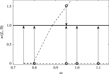
are shown in figure 1. In this figure, the horizontal axis is the inlet swirl level
 ${\it\omega}$
in the range between 0.7 and 1.15. The vertical axis is a representative parameter of each solution given by
 $w_{c}=1+{\it\epsilon}_{1}C(A_{s})$
, where
 $C(A_{s})$
equals the first maximum value of
 $A_{s}(X)$
when the inlet slope is positive or the first minimum value of
 $A_{s}(X)$
when the inlet slope is negative.
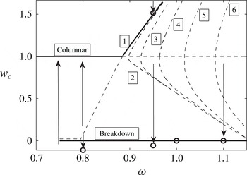
Bifurcation diagram of steady states for inviscid axisymmetric flow, Lamb–Oseen vortex,
 $b=4$
. Solid lines represent stable states and dashed lines represent unstable states. Numbers in boxes represent branch numbers. Arrows represent flow evolution at certain swirls. Circles represent the time-asymptotic results of simulations.

The branch of columnar states is represented by the line
 $w_{c}=1$
. Branch 1 bifurcates at the state with the first critical swirl,
 ${\it\omega}_{1}=0.8845$
, and exhibits a transcritical bifurcation. When
 ${\it\omega}<{\it\omega}_{1}$
, these states describe flow deceleration along the pipe centreline and acceleration near the wall, with minimum axial velocity at the outlet centreline that decreases as
 ${\it\omega}$
decreases from
 ${\it\omega}_{1}$
. When
 ${\it\omega}>{\it\omega}_{1}$
, these states describe acceleration along the pipe centreline and deceleration near the wall, with maximum axial velocity at the outlet centreline that increases as
 ${\it\omega}$
increases above
 ${\it\omega}_{1}$
. Branches 2, 3 and so on bifurcate at
 ${\it\omega}_{2}=0.8977,{\it\omega}_{3}=0.9241$
and so on, and describe steady waves with increasing wavenumber as branch number
 $n$
increases. These branches exhibit fold points at swirl levels
 ${\it\omega}_{2f}=0.8973,{\it\omega}_{3f}=0.9238$
and so on. Although some of the solutions have similar values of
 $w_{c}$
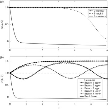
, they represent different solutions according to branch number and therefore have different shapes. Figure 2(a) shows an example of the centreline axial velocity,
 $w(x,0)$
, computed from the two possible equilibria found from the weakly nonlinear problem at
 ${\it\omega}=0.8$
, which is below
 ${\it\omega}_{1}$
. One solution is the trivial columnar solution and the other is a solitary-wave solution on branch 1 (the third solution shown in figure 2(a) is discussed in the next paragraph). Figure 2(b) shows another example of
 $w(x,0)$
computed from the six possible equilibria of the columnar flow branch and branches 1, 2 and 3 found from the weakly nonlinear problem at
 ${\it\omega}=0.95$
(the seventh solution shown in figure 2(b) is also discussed in the next paragraph). In a similar way, solutions are found for other swirl ratios in the range studied.
The possible equilibria of a swirling flow at (a) three states at
 ${\it\omega}=0.8$
, and (b) seven states at
 ${\it\omega}=0.95$
.

In addition to the steady states found from the weakly nonlinear model (3.3), Wang & Rusak (Reference Wang and Rusak1997a
) proved that, for each
 ${\it\omega}$
in the range
 $0\leqslant {\it\omega}<{\it\omega}_{0}$
, there exists only one steady-state solution of the problem (2.1), which is the columnar flow solution. This additional critical swirl,
 ${\it\omega}_{0}$
, is less than
 ${\it\omega}_{1}$
and slightly changes with
 $L$
. For the Lamb–Oseen vortex with
 $b=4$
, it was found that
 ${\it\omega}_{0}=0.731$
in a very long pipe. The present simulations show that
 ${\it\omega}_{0}=0.738$
for the case of
 $L=6$
. A branch of breakdown states bifurcates at
 ${\it\omega}_{0}$
for which
 $w_{c}=0$
for all
 ${\it\omega}$
greater than
 ${\it\omega}_{0}$
; see again figure 1. Wang & Rusak (Reference Wang and Rusak1997a
) also proved that the part of branch 1 with
 ${\it\omega}<{\it\omega}_{1}$
connects with the branch of breakdown states at
 ${\it\omega}_{0}$
, making the special breakdown state at
 ${\it\omega}_{0}$
a critical fold point. As a result, the inviscid steady-state version of problem (2.1) with assumed boundary conditions has three solutions in the range
 ${\it\omega}_{0}<{\it\omega}<{\it\omega}_{1}$
: the columnar solution, the decelerated flow state of branch 1 and the breakdown state. In the range
 ${\it\omega}_{1}<{\it\omega}<{\it\omega}_{2f}$
, there also exist three solutions: the columnar solution, the accelerated flow state of branch 1 and the breakdown state. When
 ${\it\omega}_{2f}<{\it\omega}<{\it\omega}_{3f}$
, there exist five solutions: the columnar state, the accelerated flow state of branch 1, two wavy states of branch 2 and the breakdown state. Additional steady-state solutions appear in sequence as
 ${\it\omega}$
is further increased, and they all include the columnar state, the accelerated flow state of branch 1 and the breakdown state among the numerous solutions. Figure 2(a,b) shows examples of the solution of the centreline axial velocity,
 $w(x,0)$
, for the computed breakdown states from the time-asymptotic state of the flow simulation at
 ${\it\omega}=0.8$
and
 $0.95$
, respectively, in addition to the other solutions found from the weakly nonlinear problem. Figures 1 and 2 demonstrate the complicated manifold of equilibria that the swirling flow in the pipe may take with the increase of inlet swirl from 0 to above
 ${\it\omega}_{1}$
.
Following Xu’s (Reference Xu2012) linear stability analysis of the various bifurcating states, that is based on (3.3), it can be shown that the columnar state has only asymptotically stable decaying in time modes when
 $0<{\it\omega}<{\it\omega}_{1}$
. However, the columnar states become unstable when
 ${\it\omega}>{\it\omega}_{1}$
, with instability modes that appear in sequence as
 ${\it\omega}$
increases. The states along branch 1 with
 ${\it\omega}_{0}<{\it\omega}<{\it\omega}_{1}$
are unstable, while the states along branch 1 with
 ${\it\omega}>{\it\omega}_{1}$
also have only asymptotically stable decaying in time modes. All states along branches 2, 3 and so on are unstable. The numerical computations described below show that the breakdown states bifurcating at
 ${\it\omega}_{0}$
are stable in the range of swirl studied. Therefore the dynamical problem (2.1) with assumed boundary conditions has only one stable steady-state solution when
 $0<{\it\omega}<{\it\omega}_{0}$
, which is the columnar state. When
 ${\it\omega}_{0}<{\it\omega}<{\it\omega}_{1}$
, there exist two possible stable steady states: the columnar state and the breakdown state. Initial conditions will dictate the flow evolution to one of these states. Sufficiently small disturbances on the columnar state will decay in time, while larger disturbances may evolve to breakdown states. When
 ${\it\omega}>{\it\omega}_{1}$
, there also exist two possible stable steady states: the accelerated flow state along branch 1 and the breakdown state. Again, initial conditions will dictate the flow dynamics. Computations using the unsteady weakly nonlinear problem as well as flow simulations show that, starting from small perturbations, the flow is more naturally drawn to the breakdown state; only specific large accelerating perturbations can lead the flow to the accelerated flow states. Figure 1 summarizes the expected dynamics of inviscid axisymmetric swirling flows in a finite-length pipe; solid lines represent stable states and dashed lines represent unstable states.
4.2. Simulations of inviscid flow evolution
We use the inviscid flow simulation code based on (2.1) and assumed boundary conditions to demonstrate the axisymmetric swirling flow dynamics. In all simulations, we assume an initial condition given by
 $$\begin{eqnarray}\left.\begin{array}{@{}rcl@{}}\displaystyle {\it\psi}(x,y,0)\ & =\ & \displaystyle {\it\psi}_{0}(y)+{\it\delta}{\it\epsilon}_{1}{\it\phi}_{B}(y)\sin \left(\frac{{\rm\pi}x}{2L}\right),\\ \displaystyle {\it\chi}(x,y,0)\ & =\ & \displaystyle -{\it\psi}_{0yy}-{\it\delta}{\it\epsilon}_{1}\left({\it\phi}_{Byy}-\frac{{\rm\pi}^{2}}{4L^{2}}{\it\phi}_{B}\right)\sin \left(\frac{{\rm\pi}x}{2L}\right),\\ \displaystyle K(x,y,0)\ & =\ & \displaystyle {\it\omega}K_{0}(y)+{\it\delta}{\it\epsilon}_{1}{\it\omega}_{B}\frac{K_{0y}}{{\it\psi}_{0y}}\sin \left(\frac{{\rm\pi}x}{2L}\right).\end{array}\right\}\end{eqnarray}$$
Here
 ${\it\delta}$
represents the initial perturbation size. When
 ${\it\delta}>0$
, the initial perturbation describes an accelerating flow along the pipe centreline; while when
 ${\it\delta}<0$
, it describes a decelerating flow. Results of simulations are presented as well as compared to the weakly nonlinear predictions.
The inviscid flow simulations show that, starting with either small or large, decelerating or accelerating flow perturbations, the flow always evolves to a columnar state when
 $0\leqslant {\it\omega}<{\it\omega}_{0}$
, as predicted by the theory described above. In the range of incoming swirl
 ${\it\omega}_{0}\leqslant {\it\omega}\leqslant {\it\omega}_{1}$
, sufficiently small perturbations evolve to the columnar state. However, larger perturbations evolve to breakdown states. For example, the simulations show that, starting from initial flow perturbation with
 ${\it\delta}>-12$
at
 ${\it\omega}=0.8$
, the flow always evolves to a columnar state. On the other hand, a larger initial perturbation with
 ${\it\delta}<-12$
always evolves to the breakdown state at
 ${\it\omega}=0.8$
.
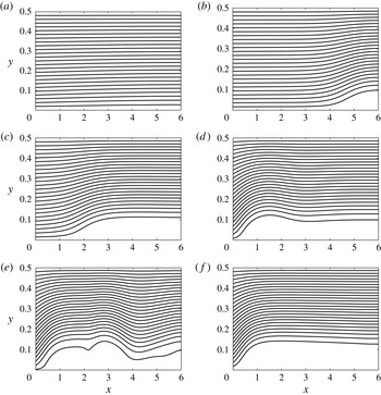
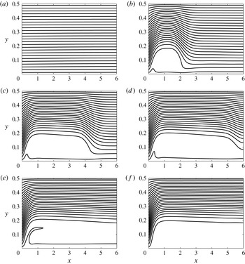
Figure 3 describes a representative example of the evolution of an initially perturbed columnar flow with
 ${\it\delta}=-15$
to the breakdown state at
 ${\it\omega}=0.8$
. In each panel, flow runs from left to right, the left edge of the panel is the inlet, the right edge is the outlet, the bottom edge is the centreline
 ${\it\psi}=0$
and the upper edge is the pipe wall
 ${\it\psi}=0.5$
. There are 25 equispaced contour lines in each panel, ranging from 0.01 to 0.49. At this below-critical inlet swirl case, the initial perturbation (figure 3
a) grows near the outlet to a finite-size near-stagnation zone at
 $t=66$
(figure 3
b) that moves upstream towards the inlet (figure 3
c,d). Once near the inlet, waves are generated along the interface of the zone and are convected downstream (figure 3
e) until a time-asymptotic state with a breakdown zone that stretches to the outlet is established when
 $t>153$
(figure 3
f). Over most of the domain (
 $x>2$
) the flow is parallel to the finite-size breakdown zone. This flow evolution is described schematically in figure 1 by the arrow at
 ${\it\omega}=0.8$
pointing from a nearly columnar flow where
 $w_{c}=0.1$
to the breakdown state at that swirl level for which
 $w_{c}=-0.11$
.
Streamfunction contour-line snapshots of flow evolution from a near-columnar state to a breakdown state when
 ${\it\omega}=0.8$
at (a)
 $t=0$
, (b)
 $t=66$
, (c)
 $t=105$
, (d)
 $t=124$
, (e)
 $t=134$
and ( f)
 $t=153$
. Initial perturbation is with
 ${\it\delta}=-15$
.

Similar results are found from simulations at various
 ${\it\omega}$
between
 ${\it\omega}_{0}$
and
 ${\it\omega}_{1}$
. Smaller limit perturbations are needed to access the breakdown states as
 ${\it\omega}$
approaches
 ${\it\omega}_{1}$
. Moreover, by starting from the breakdown state at
 ${\it\omega}=0.75$
and reducing
 ${\it\omega}$
in small steps to 0.738, we find that the flow returns to a columnar state (details are not shown). This process is presented in figure 1 by the arrow at
 ${\it\omega}=0.738$
that starts at
 $w_{c}=0$
and ends at
 $w_{c}=1$
. This computation demonstrates that
 ${\it\omega}_{0}=0.738$
for a swirling flow in a pipe with length
 $L=6$
. Also, a hysteresis loop in the cross-over between the columnar and breakdown states is realized in the range of
 ${\it\omega}_{0}$
to
 ${\it\omega}_{1}$
.
Figure 4 presents for
 ${\it\omega}=0.95>{\it\omega}_{1}$
streamfunction contour line snapshots of the flow evolution from an initially perturbed near-columnar flow state with
 ${\it\delta}=-4$
to a breakdown state. The small initial perturbation (figure 4
a) focuses near the inlet, grows in time and changes in space, forming an increasing flow deceleration along the centreline. At
 $t=60$
, the disturbance is sufficiently large to form a stagnation point along the centreline near the inlet (figure 4
b). From this stage, a low-speed zone around the centreline is established and spreads in time both radially and axially (figure 4
c–e). Eventually, when
 $t>196$
, the flow stabilizes on a time-asymptotic breakdown state, which describes a swirling flow that splits around a finite-size, nearly stagnant zone that stretches from near the inlet to the outlet (figure 4
f). Over most of the domain (
 $x>2$
) the flow is parallel to the finite-size breakdown zone. This flow evolution is described schematically in figure 1 by the arrow at
 ${\it\omega}=0.95$
pointing from a nearly columnar flow where
 $w_{c}=0.89$
to the breakdown state at that swirl level for which
 $w_{c}=-0.05$
.
Streamfunction contour-line snapshots of flow evolution from a near-columnar state to a breakdown state when
 ${\it\omega}=0.95$
at (a)
 $t=0$
, (b)
 $t=60$
, (c)
 $t=85$
, (d)
 $t=110$
, (e)
 $t=159$
and ( f)
 $t=196$
. Initial perturbation is with
 ${\it\delta}=-4$
.

Figure 5 presents another example of flow dynamics to breakdown at a higher incoming swirl ratio,
 ${\it\omega}=1.1$
. The figure shows the flow evolution from an initially perturbed near-columnar flow state with
 ${\it\delta}=-4$
(figure 5
a) to a breakdown state at this swirl level (figure 5
f). This flow evolution is described schematically in figure 1 by the arrow at
 ${\it\omega}=1.1$
pointing from
 $w_{c}=0.89$
to
 $w_{c}=0$
.
Streamfunction contour-line snapshots of flow evolution from a near-columnar state to a breakdown state when
 ${\it\omega}=1.1$
at (a)
 $t=0$
, (b)
 $t=36$
, (c)
 $t=58$
, (d)
 $t=68$
, (e)
 $t=80$
and ( f)
 $t=102$
. Initial perturbation is with
 ${\it\delta}=-4$
.

Results from inviscid flow simulations for the whole range of
 ${\it\omega}$
between
 ${\it\omega}_{1}=0.8845$
and 1.15 show similar evolution of initially small decelerating flow perturbations on the columnar flow to breakdown states. We note the differences between the development of the breakdown zone at the below-critical swirl case and the above-critical swirl case (compare figures 3–5). At below-critical swirls, the breakdown waves build up near the outlet and propagate upstream, while at above-critical swirls, waves focus near the inlet and the breakdown zone spreads downstream.
When
 ${\it\omega}_{1}<{\it\omega}<{\it\omega}_{2}$
, accelerating flow perturbations evolve to the accelerated flow state on branch 1; see examples in Rusak et al. (Reference Rusak, Wang, Xu and Taylor2012). However, when
 ${\it\omega}>{\it\omega}_{2}$
, initially small accelerating flow perturbations are first attracted to the upper states of branch 2 but then turn and evolve to breakdown states. Only relatively large accelerating initial flow perturbations allow an access to the stable states along the part of branch 1 with
 ${\it\omega}>{\it\omega}_{2}$
. For example, when
 ${\it\omega}=0.95$
and
 ${\it\delta}<21$
, the flow evolves to the breakdown state; while a large perturbation with
 ${\it\delta}>21$
leads the flow to settle on the accelerated flow state (details not shown). Starting from
 ${\it\delta}=24$
at
 ${\it\omega}=0.95$
, the flow evolves to the accelerated flow state on branch 1. This process is demonstrated in figure 1 by the arrow at
 ${\it\omega}=0.95$
that starts at
 $w_{c}=1.6$
and ends at
 $w_{c}=1.51$
. Higher values of
 ${\it\delta}$
are needed to settle on these flow states at higher
 ${\it\omega}$
.
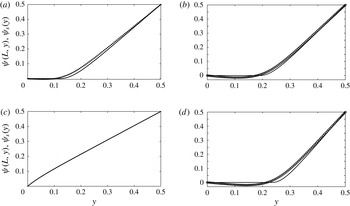
To demonstrate the correlation between the time-asymptotic states shown in figures 3–5 and the predicted states according to Wang & Rusak (Reference Wang and Rusak1997a
), we present for each state a cross-section of the outlet streamfunction profile,
 ${\it\psi}(L,y)$
(see figure 6). Also shown for each swirl level are the corresponding solutions of the columnar Squire–Long equation for the Lamb–Oseen vortex with
 $b=4$
as predicted by the theory of Wang & Rusak (Reference Wang and Rusak1997a
). It can be seen that the two solutions agree nicely for the breakdown state at
 ${\it\omega}=0.8$
and for the accelerated flow state at
 ${\it\omega}=0.95$
(figure 6
a,c). The two solutions at
 ${\it\omega}=0.95$
and
 ${\it\omega}=1.1$
are similar (figure 6
b,d). The small differences between these solutions result from the fact that in the simulations
 $L=6$
, which is not sufficiently long for the computation to fully match the theoretical prediction, which assumes a much longer pipe. Therefore, the simulation time-asymptotic states describe a slightly smaller breakdown zone than predicted by the theory. We also emphasize that, as the flow in figures 3–5 evolves to a steady state, the separation zone becomes naturally a near-stagnation zone, in accordance with Batchelor’s (Reference Batchelor1956) condition for steady inviscid-limit flows with a separation zone.
A comparison between the time-asymptotic outlet streamfunction profile
 ${\it\psi}(L,y)$
of the flow states (dotted line/circles) and the predicted outlet state
 ${\it\psi}_{s}(y)$
for a very long pipe according to the theory of Wang & Rusak (Reference Wang and Rusak1997a
) (solid line): (a)
 ${\it\omega}=0.8$
(breakdown state), (b)
 ${\it\omega}=0.95$
(breakdown state), (c)
 ${\it\omega}=0.95$
(accelerated flow state) and (d)
 ${\it\omega}=1.1$
(breakdown state).

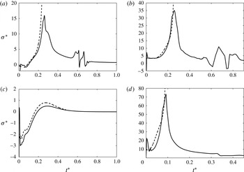
In addition, figure 7 shows the computed rescaled growth rate,
 ${\it\sigma}^{\ast }={\it\sigma}/{\it\epsilon}_{1}^{3/2}$
, of the perturbation as a function of rescaled time,
 $t^{\ast }={\it\epsilon}_{1}^{3/2}t$
, for each of the cases discussed above from the simulation and from the weakly nonlinear model, where
 ${\it\epsilon}_{1}=1/L^{2}$
. We note that these rescaled variables result from the weakly nonlinear approach in § 3 and that the use of the variable
 $t^{\ast }$
provides a rescaling of time such that phenomena occur over
 $t^{\ast }\sim O(1)$
time scale (here,
 $L=6$
and
 ${\it\epsilon}_{1}=1/36$
). Good agreement is found in the whole range of swirl between the two predictions as long as the perturbation grows from a small disturbance to the state where a stagnation point appears for the first time. We note that the initial perturbation contains various higher-order modes that are stable. The oscillations at the beginning
 $(0<t^{\ast }<0.05)$
are related to the decay of the initial perturbation to the dominant linear mode. Such a decay process may look quite oscillatory since the various higher-order modes decay at different rates. We also note that the initial stage of the process of breakdown involves faster-than-exponential growth of perturbations, and this process must be taken into account in any nonlinear control approach of the breakdown process.
A comparison between the evolution of the perturbation rescaled growth rate according to the weakly nonlinear model (dashed line) and the simulation (solid line) at (a)
 ${\it\omega}=0.8$
,
 ${\it\delta}=-15$
, (b)
 ${\it\omega}=0.95$
,
 ${\it\delta}=-4$
, (c)
 ${\it\omega}=0.95$
,
 ${\it\delta}=-24$
and (d)
 ${\it\omega}=1.1$
,
 ${\it\delta}=-4$
.

Also, the simulations show that the growth rate reaches a maximum at the state where a stagnation point appears and then it decreases as the breakdown zone evolves to the time-asymptotic state. This process of breakdown involves structural changes of the flow in the radial direction. On the other hand, the weakly nonlinear theory exhibits a singular growth of the perturbation after a stagnation point appears in the flow. This results from the limitation of the weakly nonlinear approach, which involves a fixed-in-time profile of the perturbation in the radial direction.
4.3. High-
 $\mathit{Re}$
flow states

In the case of viscous flows,
 ${\it\gamma}_{{\it\nu}}>0$
, and problem (4.1) has no trivial solution. Numerical solutions of (4.1) are computed at
 $\mathit{Re}=4000$
for a pipe length
 $L=6$
, in the range of incoming swirl
 $0.7\leqslant {\it\omega}\leqslant 0.8845$
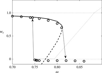
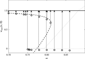
. Figure 8 presents the computed
 $w_{c}$
of these states as a function of swirl level. Here the solid line followed by the folding dashed line is from the weakly nonlinear problem. Also shown for reference is the bifurcation diagram for the inviscid flow case (dotted lines). In the high-
 $\mathit{Re}$
flow case, the branch of inviscid columnar states for
 $0<{\it\omega}<{\it\omega}_{1}$
and the branch 1 of inviscid solutions in the swirl range
 ${\it\omega}_{0}<{\it\omega}<{\it\omega}_{1}$
combine together to form a branch of steady states with a fold point at a swirl level denoted by
 ${\it\omega}_{1{\it\nu}}$
. For example, when
 $\mathit{Re}=4000$
and
 $L=6$
, we find that
 ${\it\omega}_{1{\it\nu}}=0.812$
. The upper part of this branch of solutions (
 $0<{\it\omega}<{\it\omega}_{1{\it\nu}}$
) describes (solid line in figure 8) nearly columnar flows decelerating along the centreline and accelerating along the pipe wall. Flow disturbances from columnar are relatively small and the flow achieves minimum speed at the outlet centreline, i.e.
 $w_{c}=w(L,0)$
. The lower part of the branch of solutions that folds back (
 ${\it\omega}<{\it\omega}_{1{\it\nu}}$
) describes (dashed line in figure 8) solitary-wave states with large deceleration along the centreline, specifically focused near the outlet.
Bifurcation diagram of steady states for
 $\mathit{Re}=4000$
, axisymmetric flow, Lamb–Oseen vortex,
 $b=4$
. Lines represent solutions of weakly nonlinear theory; solid lines are stable solutions and dashed lines are unstable solutions. Circles represent results from present simulations. Arrows represent flow evolution at certain swirls. Dotted lines represent the inviscid flow bifurcation diagram for reference.

This special fold behaviour of viscous swirling flows as described by the weakly nonlinear approximation is similar to the computations of Beran & Culick (Reference Beran and Culick1992) for a pipe with non-dimensional length
 $L=15$
and with no contraction. The numerical steady flow computations of Beran & Culick (Reference Beran and Culick1992) also show the appearance of steady breakdown states in a Lamb–Oseen vortex with
 $b=4$
when
 ${\it\omega}$
is greater than another special swirl level denoted by
 ${\it\omega}_{0{\it\nu}}$
, where
 ${\it\omega}_{0{\it\nu}}<{\it\omega}_{1{\it\nu}}$
. These breakdown states are characterized by a swirling flow splitting around a closed separation zone. In addition, the simulations show the existence of a continuous branch of solitary-wave states connecting between
 ${\it\omega}_{1{\it\nu}}$
and
 ${\it\omega}_{0{\it\nu}}$
. Furthermore, the unsteady flow simulations of Beran (Reference Beran1994) and Lopez (Reference Lopez1994) show that the non-columnar states and the breakdown states are stable while the solitary-wave states are unstable and are not found as time-asymptotic solutions. Similarly, our linear stability analysis of the various steady states found from the solution of (4.1) show that the non-columnar states are asymptotically stable while the solitary-wave states are unstable (see Xu Reference Xu2012). Therefore, from a dynamical perspective, only one near-columnar stable state exists when
 ${\it\omega}<{\it\omega}_{0{\it\nu}}$
, two possible stable states exist when
 ${\it\omega}_{0{\it\nu}}<{\it\omega}<{\it\omega}_{1{\it\nu}}$
(a near-columnar state and a breakdown state) and only one stable breakdown state exists in a range of swirl above
 ${\it\omega}_{1{\it\nu}}$
.
4.4. Simulations of high-
$\mathit{Re}$
flow evolution

The present unsteady viscous flow simulations for the Lamb–Oseen vortex with
 $b=4$
in a pipe with
 $L=6$
, shown by open circles in figure 8, support the flow dynamics described above. Results show the successive appearance of steady, near-columnar states with increased flow deceleration along the pipe when
 ${\it\omega}$
is increased in the range
 $0.7\leqslant {\it\omega}\leqslant 0.81$
(circles with
 $w_{c}>0$
in figure 8). Here,
 $w_{c}=w(L,0)$
. When
 ${\it\omega}$
is further increased from 0.81 to 0.82, the flow evolves from the initial near-columnar state at 0.81 to a breakdown state at 0.82. This is represented by the arrow in figure 8 connecting the point (
 ${\it\omega}=0.81,w_{c}=0.69$
) and the point (
 ${\it\omega}=0.82,w_{c}=-0.03$
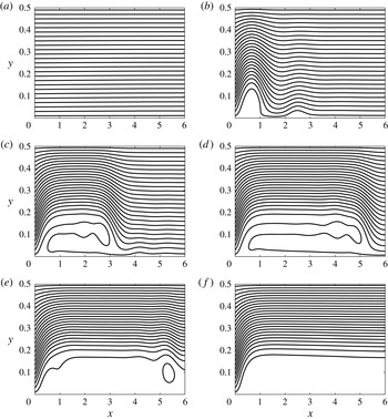
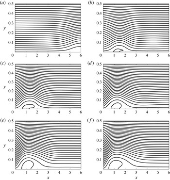
). The details of this flow transition to a breakdown state are shown in figure 9. There are 26 equispaced contour lines in each panel, ranging from 0 to 0.49. The initial wave grows near the outlet (figure 9
a), travels upstream (figure 9
b), grows in radial size around
 $x=1$
(figure 9
c) and establishes a compact separation (breakdown) zone that fluctuates at its back side between
 $x=1$
and
 $x=2$
at a low frequency (figure 9
d–f). This transition also demonstrates that the branch of near-columnar states folds at
 ${\it\omega}_{1{\it\nu}}=0.812$
.
Streamfunction contour-line snapshots of flow evolution at
 $\mathit{Re}=4000$
from an initial near-columnar state at
 ${\it\omega}=0.81$
to the breakdown state at
 ${\it\omega}=0.82$
at (a)
 $t=0$
, (b)
 $t=100$
, (c)
 $t=200$
, (d)
 $t=300$
, (e)
 $t=340$
and ( f)
 $t=380$
.

Starting from the breakdown state at
 ${\it\omega}=0.82$
, the present viscous flow simulations are successively continued in small steps to both higher swirl ratios up to
 ${\it\omega}=0.86$
and to lower swirl ratios down to
 ${\it\omega}=0.75$
. These states are represented by the circles with
 $w_{c}<0$
in figure 8. A snapshot of each of the various fluctuating breakdown states in this range of swirl is shown in figure 10. It can be seen that, as
 ${\it\omega}$
is increased from 0.75, the breakdown zone moves upstream and increases in radial extent. Note that at
 $\mathit{Re}=4000$
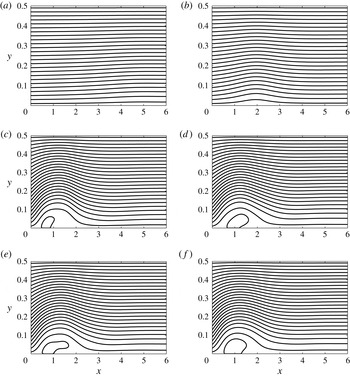
the breakdown zones are compact with axial extent of about one pipe radius and the swirling flow wraps around them and is significantly slowed down in the range downstream of the zone. These breakdown states are different from the inviscid long and wide breakdown states shown in figures 3–5, which may characterize much higher-
 $\mathit{Re}$
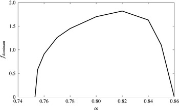
flows. The non-dimensional dominant fluctuation frequencies at the back of the breakdown zones as a function of
 ${\it\omega}$
are summarized in figure 11. The frequency is nearly zero at
 ${\it\omega}=0.75$
and 0.86 and achieves a maximum value of 1.8 at
 ${\it\omega}=0.82$
.
Streamfunction contour-line snapshots of breakdown states at
 $\mathit{Re}=4000$
at (a)
 ${\it\omega}=0.75$
, (b)
 ${\it\omega}=0.76$
, (c)
 ${\it\omega}=0.78$
, (d)
 ${\it\omega}=0.80$
, (e)
 ${\it\omega}=0.84$
and ( f)
 ${\it\omega}=0.86$
.

Non-dimensional frequency of oscillations of breakdown states as a function of
 ${\it\omega}$
, at
 $\mathit{Re}=4000$
.

Starting from the breakdown state at
 ${\it\omega}=0.75$
and reducing the swirl to 0.745, the flow evolves back to the near-columnar state at this swirl level (details not shown). This process demonstrates that
 ${\it\omega}_{0{\it\nu}}=0.748$
when
 $\mathit{Re}=4000$
and
 $L=6$
and is shown by the arrow in figure 8 pointing upwards from the point (
 ${\it\omega}=0.748,w_{c}=-0.01$
) to the point (
 ${\it\omega}=0.745,w_{c}=0.91$
).
The present simulations and weakly nonlinear computations show that, within the range of swirl ratios studies, at
 $\mathit{Re}=4000$
there is only one stable near-columnar state when
 $0<{\it\omega}<{\it\omega}_{0{\it\nu}}=0.748$
. There exist three states when
 ${\it\omega}_{0{\it\nu}}=0.748<{\it\omega}<{\it\omega}_{1{\it\nu}}=0.812$
: a stable near-columnar state, an unstable solitary-wave state and an oscillating breakdown state. Only a breakdown state with fluctuations at the back of the separation zone exists in the range of swirl
 ${\it\omega}_{1{\it\nu}}=0.812<{\it\omega}\leqslant 0.86$
, which is an attractor of flow dynamics at these swirl ratios. These results agree with those of Beran & Culick (Reference Beran and Culick1992), Beran (Reference Beran1994) and Lopez (Reference Lopez1994).
5. Insight into flow dynamics and control
Following Rusak et al. (Reference Rusak, Wang, Xu and Taylor2012), let
 $\tilde{E}(t^{\ast })=({\it\tau}/2)\int _{0}^{1}(A_{X})^{2}\,\text{d}X$
be the perturbation’s kinetic energy associated with radial velocity. We multiply (3.3) by
 $A_{XX}$
and integrate the result over the domain
 $0\leqslant X\leqslant 1$
. After integration by parts and using the boundary conditions (3.6), we find the energy identity:
 $$\begin{eqnarray}\displaystyle \frac{\text{d}\tilde{E}}{\,\text{d}t^{\ast }} & = & \displaystyle -\frac{1}{2}(A_{XX}(1,t^{\ast }))^{2}-{\it\alpha}\int _{0}^{1}(A_{X})^{3}\,\text{d}X+\frac{{\it\beta}{\it\kappa}_{{\it\omega}}}{2}(A_{X}(0,t^{\ast }))^{2}\nonumber\\ \displaystyle & & \displaystyle -\,{\it\gamma}_{{\it\nu}}A_{X}(0,t^{\ast })+{\it\gamma}_{c}U_{c}^{\ast }(t^{\ast })A_{X}(0,t^{\ast }).\end{eqnarray}$$
The term on the left-hand side describes the rate of change of the perturbation’s kinetic energy; when it is negative, the perturbation decays in time, and when it is positive, the perturbation grows. The competition between the terms on the right-hand side dictates the perturbation’s dynamics. The first term on the right-hand side results from the dispersion term in (3.3) and is always negative, stabilizing, but limited in size. The second term results from the nonlinear term in (3.3) and is positive (destabilizing) when
 $A_{X}$
is negative along most of the domain and vice versa. The third term relates to the swirl level through
 ${\it\kappa}_{{\it\omega}}$
. When
 ${\it\omega}<{\it\omega}_{B}$
, this term is negative (stabilizing), while when
 ${\it\omega}>{\it\omega}_{B}$
, this term is positive (destabilizing). The fourth term is the lumped effect of viscosity and it is positive (destabilizing) when
 $A_{X}(0,t^{\ast })$
is negative and vice versa. The last term relates to the control command.
This identity sheds insight on the natural flow dynamics when
 ${\it\gamma}_{c}=0$
. In the natural inviscid flow case,
 ${\it\gamma}_{{\it\nu}}=0$
. Then, when the perturbation is infinitesimally small, the balance between the first and third terms on the right-hand side forms a critical neutral state at the swirl level
 ${\it\omega}_{1}$
, which is greater than
 ${\it\omega}_{B}$
. The limited stabilizing effect of the first term causes the critical swirl to increase from
 ${\it\omega}_{B}$
to
 ${\it\omega}_{1}$
. In addition, when perturbations are small and
 $0<{\it\omega}<{\it\omega}_{1}$
, the first and third terms dominate the nonlinear term and enforce a negative rate of growth of the perturbation’s energy and the decay of the perturbation. However, when
 ${\it\omega}>{\it\omega}_{1}$
, the situation is reversed and the third term dominates the first and second terms to enforce a positive growth rate of the small perturbation and instability. The instability may evolve in one of two ways. When
 $A_{X}$
is negative along most of the domain, the second term supports the third term and they both combine to initiate a faster-than-exponential breakdown process. When
 $A_{X}$
is positive along most of the domain, the first and second terms combine to balance with the third term and enforce stabilization over time on the accelerated flow state. Moreover, the dominance of the third term when
 ${\it\omega}>{\it\omega}_{1}$
exhibits a feed-forward mechanism between the inlet radial velocity related to
 $A_{X}(0,t^{\ast })$
and the growth rate of the perturbation’s energy,
 $\tilde{E}(t^{\ast })$
. At above-critical swirls, a negative
 $A_{X}(0,t^{\ast })$
induces positive growth of
 $\tilde{E}(t^{\ast })$
in the bulk, which in turn acts to make
 $A_{X}(0,t^{\ast })$
more negative and increase the radial velocity at the inlet. The simulations of Rusak et al. (Reference Rusak, Wang, Xu and Taylor2012) demonstrate this feed-forward mechanism of perturbation growth, which eventually stabilizes on a breakdown state. These results shed additional light on the inviscid flow bifurcation diagram in figure 1.
The introduction of the viscous term in the high-
 $\mathit{Re}$
flow cases enforces a destabilizing effect when
 $A_{X}(0,t^{\ast })$
is negative, thus reducing the critical swirl for the appearance of breakdown from
 ${\it\omega}_{1}$
to
 ${\it\omega}_{1{\it\nu}}$
. Note that all near-columnar steady states at high-
 $\mathit{Re}$
flow cases are characterized by a negative value of
 $A_{X}(0,t^{\ast })$
. As swirl is increased along this branch of states, the viscous term eventually forces an earlier flow destabilization and evolution to breakdown states. These results shed light on the viscous flow bifurcation diagram in figure 8.
Using the identity (5.1), a fundamental control law for both inviscid and high-
 $\mathit{Re}$
flows is derived. The primary objective is to use a feedback control command for
 $U_{c}^{\ast }(t^{\ast })$
that will cut the feed-forward mechanism of the perturbation’s growth. Let
 $$\begin{eqnarray}{\it\gamma}_{c}U_{c}^{\ast }(t^{\ast })=-\frac{{\it\gamma}}{2}{\it\beta}{\it\kappa}_{{\it\omega}}A_{X}(0,t^{\ast })+{\it\gamma}_{{\it\nu}}\end{eqnarray}$$
for all
 $t^{\ast }>t_{0}^{\ast }$
. Here
 $t_{0}^{\ast }$
is the time when control is activated during the flow dynamics. The control command is composed of two terms. The first is an active control term that is related to the inlet slope,
 $A_{X}(0,t^{\ast })$
, and gain,
 ${\it\gamma}$
. The second is a passive control term that depends on
 ${\it\gamma}_{{\it\nu}}=(L^{5}/\mathit{Re})(N_{{\it\nu}}/{\it\delta}^{\ast })$
. The passive command is used to eliminate the destabilizing effect of viscosity.
Inserting this control law into (5.1), we find that
 $$\begin{eqnarray}\frac{\text{d}\tilde{E}}{\,\text{d}t^{\ast }}\leqslant -{\it\alpha}\int _{0}^{1}(A_{X})^{3}\,\text{d}X+(1-{\it\gamma})\frac{{\it\beta}{\it\kappa}_{{\it\omega}}}{2}(A_{X}(0,t^{\ast }))^{2}.\end{eqnarray}$$
Note that the viscous term is completely eliminated in (5.3) by the assumed feedback control command and that the effect of dispersion is removed since it is always a negative term.
It is clear from (5.3) that, when
 ${\it\kappa}_{{\it\omega}}>0$
and the initial perturbation is small, the use of
 ${\it\gamma}>1$
in the feedback control command cuts the natural feed-forward mechanism of the perturbation’s growth. It enforces a negative rate of change of the perturbation’s energy, the decay of the perturbation and the return of the flow to a columnar state, even at high-
 $\mathit{Re}$
flow cases where no columnar state exists naturally. This is supported by the linear stability analysis of the flow control problem in Wang et al. (Reference Wang, Rusak, Taylor and Gong2013), which showed that all modes of perturbations are stabilized for a wide range of swirl up to 50 % above
 ${\it\omega}_{1}$
. Moreover, when the initial perturbation is large, a sufficiently large
 ${\it\gamma}$
may overcome the steepening effect from the nonlinear term and enforce the decay of the perturbation and establishment of a columnar state. When
 ${\it\kappa}_{{\it\omega}}<0$
, the use of
 ${\it\gamma}<0$
keeps a feedback effect in the control law (5.2) and, with sufficiently negative
 ${\it\gamma}$
, may overcome the nonlinear effect and again stabilize the flow to a columnar state. As the perturbation decays,
 $A_{X}(0,t^{\ast })$
tends to zero and the control command approaches a constant value
 $U_{c}={\it\gamma}_{{\it\nu}}/{\it\gamma}_{c}$
that overcomes the destabilizing effect of viscosity in the bulk. The computed examples in § 6 demonstrate these ideas, specifically for initial states with a vortex breakdown zone.
To accommodate the control law (5.2) in the weakly nonlinear approach, we define
 $t_{0}$
(and
 $t_{0}^{\ast }={\it\epsilon}_{1}^{3/2}t_{0}$
) as the initial time for the activation of the feedback control command and
 $T_{s}$
(and
 $T_{s}^{\ast }={\it\epsilon}_{1}^{3/2}T_{s}$
) as the rise time of the control command from zero to a full command as a linear function in time. This means that
 $$\begin{eqnarray}\displaystyle U_{c}^{\ast }=\left\{\begin{array}{@{}ll@{}}\displaystyle 0 & \displaystyle \text{when }t^{\ast }<t_{0}^{\ast },\\ \displaystyle \frac{t^{\ast }-t_{0}^{\ast }}{{\it\gamma}_{c}T_{s}^{\ast }}\left[-\frac{{\it\gamma}}{2}{\it\beta}{\it\kappa}_{{\it\omega}}A_{X}(0,t^{\ast })+{\it\gamma}_{{\it\nu}}\right] & \displaystyle \text{when }t_{0}^{\ast }\leqslant t^{\ast }\leqslant t_{0}^{\ast }+T_{s}^{\ast },\\ \displaystyle -\frac{{\it\gamma}}{2{\it\gamma}_{c}}{\it\beta}{\it\kappa}_{{\it\omega}}A_{X}(0,t^{\ast })+\frac{{\it\gamma}_{{\it\nu}}}{{\it\gamma}_{c}} & \displaystyle \text{when }t^{\ast }>t_{0}^{\ast }+T_{s}^{\ast }.\end{array}\right. & & \displaystyle\end{eqnarray}$$
In this way, we present some realism to the activation of the control command. Also it allows a degree of freedom in the design of an effective control command.
Actively controlled inviscid flow properties as a function of time according to the weakly nonlinear control problem when
 ${\it\omega}=1.1$
from a simulated breakdown state to a columnar state: (a)
 $w_{min},w_{max},w(L,0)$
and (b)
 $U_{c}$
. Control command is with
 ${\it\gamma}=1.5$
.

The control command (5.4) is used in the weakly nonlinear problem (3.3) to control the perturbation dynamics. We conducted parametric studies for various values of
 ${\it\omega}$
and
 $\mathit{Re}$
, starting from a wide range of initial conditions and using numerous values of
 ${\it\gamma}$
,
 $t_{0}^{\ast }$
and
 $T_{s}^{\ast }$
. Figure 12 shows an example of such computations for the inviscid flow case with
 ${\it\omega}=1.1$
,
 $L=6$
and initial condition
 $A(X,0)$
computed from the centreline axial velocity of the breakdown state at this swirl level,
 $A(X,0)=[w(X,0)-1]/{\it\epsilon}_{1}$
(see figure 5
f). We use in this case the following control parameters:
 ${\it\gamma}=1.5$
,
 $t_{0}^{\ast }=0$
and
 $T_{s}^{\ast }=0.035$
. It can be seen from figure 12(a) that the values of the minimum centreline axial velocity (
 $w_{min}$
), the maximum centreline axial velocity (
 $w_{max}$
) and the outlet centreline axial velocity (
 $w(L,0)$
) exhibit a quick transition during the time period
 $0<t^{\ast }<0.05$
and then decay exponentially in time to unity. Similarly, figure 12(b) shows that the control command,
 $U_{c}={\it\epsilon}_{1}^{5/2}U_{c}^{\ast }$
, quickly increases from zero to a maximum of 0.41 at
 $t^{\ast }=0.015$
, sharply decreases to a minimum of
 $-0.045$
at
 $t^{\ast }=0.04$
and then decays exponentially in time back to zero. The flow wall injection changes to suction when
 $U_{c}$
is negative. The controlled flow returns after
 $t^{\ast }>0.4$
to a columnar state with an exponentially small control command. This example demonstrates the feasibility of using the proposed active feedback flow control law to eliminate the vortex breakdown zone and maintain the flow to stay columnar. The control needs to stay active for all time, even though the flow is essentially columnar and the command is exponentially small. Turning off the control command at some point results in the evolution of the perturbation over time back to a breakdown zone.
Another example focuses on the flow case where
 ${\it\omega}=0.82$
,
 $L=6$
and
 $\mathit{Re}=4000$
with initial conditions
 $A(X,0)$
computed from the centreline axial velocity of the breakdown state at these conditions (see figure 9
f). We use in this case the following control parameters:
 ${\it\gamma}=-2$
,
 $t_{0}^{\ast }=0$
and
 $T_{s}^{\ast }=0.023$
. It can be seen from figure 13(a) that the values of the minimum centreline axial velocity (
 $w_{min}$
), the maximum centreline axial velocity (
 $w_{max}$
) and the outlet centreline axial velocity (
 $w(L,0)$
) exhibit an oscillatory transition during the time period
 $0<t^{\ast }<0.3$
and then decay exponentially in time to almost unity. Similarly, figure 13(b) shows that the control command,
 $U_{c}={\it\epsilon}_{1}^{5/2}U_{c}^{\ast }$
, quickly increases from zero to a maximum of 0.046 at
 $t^{\ast }=0.023$
, sharply decreases and then decays exponentially in time to a constant value, 0.002. The controlled flow returns after
 $t^{\ast }>0.5$
to an almost columnar state with a constant small value of control command. The control command becomes small when
 $t^{\ast }>0.2$
and it only neutralizes the destabilizing effect of viscosity in the bulk. Then, the decay of the perturbation is dominated by the natural stability of the inviscid flow at this below-critical swirl level.
Actively controlled flow properties when
 $\mathit{Re}=4000$
as a function of time according to the weakly nonlinear control problem when
 ${\it\omega}=0.82$
from a simulated breakdown state to a columnar state: (a)
 $w_{min},w_{max},w(L,0)$
and (b)
 $U_{c}$
. Control command is with
 ${\it\gamma}=-2$
.

Using similar flow computations based on the weakly nonlinear model, we find the best values of
 ${\it\gamma}$
and
 $T_{s}^{\ast }$
to minimize the maximum of the control command,
 $U_{c}$
, as well as to achieve a smooth return to the columnar state within the shortest time. The parametric study for the Lamb–Oseen vortex with
 $b=4$
shows best performances when
 ${\it\gamma}{\it\beta}{\it\kappa}_{{\it\omega}}$
remains nearly constant (around a value of 5.3) for
 ${\it\omega}$
around
 ${\it\omega}_{B}$
(
 $0.82\leqslant {\it\omega}\leqslant 0.95$
). This means that
 ${\it\gamma}$
grows in its absolute value as
 ${\it\omega}$
approaches
 ${\it\omega}_{B}$
. When
 ${\it\omega}>0.95$
, the best control is achieved with
 ${\it\gamma}\sim 2$
; however, rise time has to increase with
 ${\it\omega}$
. When
 $0.75<{\it\omega}<0.82$
, the best control is achieved by changing the value of
 ${\it\gamma}$
from
 $-2$
at
 ${\it\omega}=0.82$
to
 $-0.75$
at
 ${\it\omega}=0.75$
. Note that too small or too large values of
 ${\it\gamma}$
around these best values may result in either complete loss of control or ineffective control of the flow, with either too long time to decay or many oscillations on the way to decay. Corresponding rise times range from
 $T_{s}^{\ast }=0.006$
to
 $T_{s}^{\ast }=0.035$
. Smaller rise times may induce a too sharp initiation of the controller, while larger rise times may result in too late initiation of control. Both may cause loss of control.
6. Computed examples of controlled flows
The proposed control law (5.4) from the weakly nonlinear theory is applied through the following steps to numerical simulations of controlled flow dynamics according to (2.1) and assumed boundary conditions (see details in Granata Reference Granata2014). We first choose a point,
 $y_{m}=0.11$
, at the pipe inlet, where for all time
 $t>t_{0}$
we measure
 ${\it\psi}_{x}(0,y_{m},t)$
using a forward finite-difference scheme. Benjamin’s critical function,
 ${\it\phi}_{B}$
, achieves a maximum around
 $y_{m}=0.11$
. Note that the measurement of
 ${\it\psi}_{x}(0,y_{m},t)$
is related to the inlet radial velocity,
 ${\it\psi}_{x}(0,y_{m},t)=-\sqrt{2y_{m}}\,u(0,y_{m},t)$
. Using the asymptotic approximation (3.2) for
 ${\it\psi}(x,y,t)$
, we estimate
 $A_{X}(0,t^{\ast })={\it\psi}_{x}(0,y_{m},t)/[{\it\epsilon}_{1}^{3/2}{\it\phi}_{B}(y_{m})]$
. Substituting this into (5.4), we find that the control command of wall injection/suction becomes for all
 $t>t_{0}$
:
 $$\begin{eqnarray}\displaystyle U_{c}(t)=\left\{\begin{array}{@{}ll@{}}\displaystyle 0 & \displaystyle \text{when }t<t_{0},\\ \displaystyle \frac{t-t_{0}}{T_{s}}\left[-{\it\epsilon}_{1}\frac{{\it\gamma}{\it\beta}{\it\kappa}_{{\it\omega}}}{2{\it\gamma}_{c}{\it\phi}_{B}(y_{m})}{\it\psi}_{x}(0,y_{m},t)+{\it\epsilon}_{1}^{5/2}\frac{{\it\gamma}_{{\it\nu}}}{{\it\gamma}_{c}}\right] & \displaystyle \text{when }t_{0}\leqslant t\leqslant t_{0}+T_{s},\\ \displaystyle -{\it\epsilon}_{1}\frac{{\it\gamma}{\it\beta}{\it\kappa}_{{\it\omega}}}{2{\it\gamma}_{c}{\it\phi}_{B}(y_{m})}{\it\psi}_{x}(0,y_{m},t)+{\it\epsilon}_{1}^{5/2}\frac{{\it\gamma}_{{\it\nu}}}{{\it\gamma}_{c}} & \displaystyle \text{when }t>t_{0}+T_{s}.\end{array}\right. & & \displaystyle\end{eqnarray}$$
As a result, the wall values of
 $K$
and
 ${\it\eta}$
must acknowledge the control command,
 ${\it\psi}_{x}(x,1/2,t)=U_{c}(t)$
for
 $0\leqslant x\leqslant L$
, and are updated according to (2.1). In addition, the wall boundary condition for the solution of
 ${\it\psi}$
in the controlled flow simulations becomes
 $$\begin{eqnarray}\displaystyle {\it\psi}(x,1/2,t)=\left\{\begin{array}{@{}l@{}}\displaystyle {\it\psi}_{0}(1/2)\quad \text{when }t<t_{0},\\ \displaystyle {\it\psi}_{0}(1/2)+\frac{t-t_{0}}{T_{s}}\left[-{\it\epsilon}_{1}\frac{{\it\gamma}{\it\beta}{\it\kappa}_{{\it\omega}}}{2{\it\gamma}_{c}{\it\phi}_{B}(y_{m})}{\it\psi}_{x}(0,y_{m},t)+{\it\epsilon}_{1}^{5/2}\frac{{\it\gamma}_{{\it\nu}}}{{\it\gamma}_{c}}\right]x\\ \displaystyle \qquad \text{when }t_{0}\leqslant t\leqslant t_{0}+T_{s},\\ \displaystyle {\it\psi}_{0}(1/2)+\left[-{\it\epsilon}_{1}\frac{{\it\gamma}{\it\beta}{\it\kappa}_{{\it\omega}}}{2{\it\gamma}_{c}{\it\phi}_{B}(y_{m})}{\it\psi}_{x}(0,y_{m},t)+{\it\epsilon}_{1}^{5/2}\frac{{\it\gamma}_{{\it\nu}}}{{\it\gamma}_{c}}\right]x\\ \displaystyle \qquad \text{when }t>t_{0}+T_{s},\end{array}\right. & & \displaystyle\end{eqnarray}$$
for
 $0\leqslant x\leqslant L$
and for all
 $t>t_{0}$
. This boundary condition was implemented in the numerical solution of the Poisson solver for the spatial integration of
 ${\it\psi}$
in terms of
 ${\it\chi}$
. Mesh convergence studies of several representative test cases of the controlled flow dynamics are presented in Granata (Reference Granata2014). It is found again that a mesh of 100 × 100 grid points in both the
 $x$
and
 $y$
directions is a sufficiently fine mesh for converged solutions.
We present a series of examples for both inviscid and high-
 $\mathit{Re}$
flow cases that demonstrate the controlled dynamics of swirling flows in a finite-length pipe. In each case we present snapshots of the flow controlled dynamics and the control command. The instantaneous mass flux ratio
 ${\dot{m}}_{in}(t)$
of the injected or sucked flux through the wall (
 $2{\rm\pi}Rl{\it\rho}W_{0}U_{c}(t)$
) divided by the flow axial flux
 $({\rm\pi}R^{2}{\it\rho}W_{0})$
entering the inlet is defined by
 $$\begin{eqnarray}{\dot{m}}_{in}(t)=2LU_{c}(t).\end{eqnarray}$$
The corresponding momentum coefficient
 $C_{{\it\mu}}$
is defined by
 $$\begin{eqnarray}C_{{\it\mu}}=2LU_{c}^{2}(t).\end{eqnarray}$$
We also define the non-dimensional control response time
 ${\rm\Delta}t$
as the time passed from just after application of control to a stabilization of the core flow on a near-columnar state.
Streamfunction contour-line snapshots of actively controlled inviscid flow evolution from an initial vortex breakdown state to a columnar state when
 ${\it\omega}=0.95$
at (a)
 $t=196$
, (b)
 $t=199$
, (c)
 $t=204$
, (d)
 $t=214$
, (e)
 $t=228$
and ( f)
 $t=282$
. Control command is with
 ${\it\gamma}=2$
.

6.1. Control of inviscid-limit swirling flows
Figure 14 presents snapshots of the actively controlled dynamics of a Lamb–Oseen vortex with
 $b=4$
,
 ${\it\omega}=0.95>{\it\omega}_{1}$
and
 $L=6$
. In each panel, flow runs from left to right, the left edge is the inlet, the right edge is the outlet, the bottom edge is the centreline
 ${\it\psi}=0$
and the upper edge is the pipe wall
 $y=0.5$
. We continued the simulation shown in figure 4, and at time
 $t_{0}=196.6$
(
 $t_{0}^{\ast }=0.91$
), where the flow had established a breakdown state, we initiated a control command with gain
 ${\it\gamma}=2$
and rise time of
 $T_{s}=1.5$
(
 $T_{s}^{\ast }=0.007$
). Figure 15(a) shows the perturbation’s minimum, maximum and outlet values of the axial velocity after control has been initiated. Figure 15(b) shows the control command
 $U_{c}$
as a function of
 $t^{\ast }$
. Under the initial injection, the control command rises from zero to a maximum value of
 $U_{c}=0.115$
(
 ${\dot{m}}_{in}=1.38$
,
 $C_{{\it\mu}}=0.159$
) at
 $t=199$
(
 $t^{\ast }=0.921$
). The initial large breakdown zone (figure 14
a) collapses to a much smaller zone near the inlet over a short time period of two time units (figure 14
b at
 $t=199$
). As a result, the radial velocity at the inlet decreases at
 $y_{m}=0.11$
and the injection is reduced. This is followed up by a further diffusion of the zone over time (figure 14
c,d) with further reduction of injection. At
 $t=217$
(
 $t^{\ast }=1.005$
), the wall injection turns into slight wall suction, which grows to a minimum of
 $U_{c}=-0.0025~({\dot{m}}_{in}=-0.03,C_{{\it\mu}}=0.000075)$
at
 $t=227$
(
 $t^{\ast }=1.051$
) and then decays to zero. The accelerated flow along the centreline decays exponentially over time (figure 14
e, f) and the flow stabilizes on a columnar state when
 $t>432$
(
 $t^{\ast }>2$
). The non-dimensional control response time is
 ${\rm\Delta}t\sim 236$
. This demonstrates for the first time the feasibility of eliminating the vortex breakdown state and stabilizing on a columnar state in an above-critical swirl flow based on the axisymmetric Euler equations. Figures 4 and 14 together show a complete continuous process of how a columnar vortex flow in a pipe with above-critical swirl evolves from a small perturbation to a breakdown state and then, with the initiation of active feedback flow control, returns to a columnar state with an asymptotically decaying control command.
Actively controlled inviscid flow properties as a function of time when
 ${\it\omega}=0.95$
: (a)
 $w_{min},w_{max},w(L,0)$
and (b)
 $U_{c}$
. Control command is with
 ${\it\gamma}=2$
.

We further explore the capabilities to control swirling flows in a pipe at higher swirl levels. Successful control has been achieved for all swirl levels up to
 ${\it\omega}=1.15$
, which is 30 % above the critical value. The controlled flow dynamics of a Lamb–Oseen vortex with
 $b=4$
,
 ${\it\omega}=1.1>{\it\omega}_{1}$
and
 $L=6$
is shown in figures 16 and 17. We again continued the simulation shown in figure 5, and at time
 $t_{0}=102.2$
(
 $t_{0}^{\ast }=0.474$
), where the flow had established a time-asymptotic breakdown state, we initiated a control command with gain
 ${\it\gamma}=1.5$
and rise time of
 $T_{s}=7.5$
(
 $T_{s}^{\ast }=0.035$
). The dynamics as well as the control command are similar to those shown in figures 14 and 15, but occur over a shorter time scale. The control command increases from zero to a maximum injection of
 $U_{c}=0.24$
(
 ${\dot{m}}_{in}=2.88$
,
 $C_{{\it\mu}}=0.691$
), at
 $t=106$
(
 $t^{\ast }=0.491$
), then quickly decreases, turns into suction with a minimum of
 $U_{c}=-0.038$
(
 ${\dot{m}}_{in}=-0.456$
,
 $C_{{\it\mu}}=0.017$
) at
 $t=115$
(
 $t^{\ast }=0.532$
) and then decays to zero. The control command is higher than in the previous case to compensate for the stronger vortex breakdown with larger radial velocity at the inlet at the higher swirl. The flow returns to a columnar state when
 $t>300$
(
 $t^{\ast }>1.4$
). The non-dimensional control time response is
 ${\rm\Delta}t\sim 200$
. Again, figures 5 and 16 together show another example of a complete continuous process of how a columnar vortex flow in a pipe with above-critical swirl evolves from a small perturbation to a breakdown state and then, with the initiation of active flow control, returns to a columnar state with an asymptotically decaying control command.
Streamfunction contour-line snapshots of actively controlled inviscid flow evolution from an initial vortex breakdown state to a columnar state when
 ${\it\omega}=1.1$
at (a)
 $t=102.2$
, (b)
 $t=102.4$
, (c)
 $t=107.4$
, (d)
 $t=116.4$
, (e)
 $t=142$
and ( f)
 $t=272$
. Control command is with
 ${\it\gamma}=1.5$
.

Actively controlled inviscid flow properties as a function of time when
 ${\it\omega}=1.1$
: (a)
 $w_{min},w_{max},w(L,0)$
and (b)
 $U_{c}$
. Control command is with
 ${\it\gamma}=1.5$
.

We also demonstrate the ability of the proposed control law to eliminate accelerated flow states when
 ${\it\omega}>{\it\omega}_{1}$
. For example, in the case of
 ${\it\omega}=0.95$
and
 $L=6$
, we started from the time-asymptotic accelerated flow state, and at time
 $t_{0}=1253$
(
 $t_{0}^{\ast }=5.8$
) we initiated the active control command. Here the control gain is
 ${\it\gamma}=2$
and the rise time is
 $T_{s}=1.5$
. Figure 18(a) shows the maximum, minimum and outlet values of the axial velocity as a function of time (
 $t^{\ast }$
), and figure 18(b) shows the corresponding evolution of the control command,
 $U_{c}$
. In this case, suction is first introduced and causes the flow to decelerate with a minimum suction of
 $U_{c}=-0.0043$
(
 ${\dot{m}}_{in}=-0.052$
,
 $C_{{\it\mu}}=0.0002$
) at time
 $t=1268$
(
 $t^{\ast }=5.87$
). Then, the perturbation decays over time and the suction is reduced. The controller exhibits oscillatory decay, which involves changes between slight suction and injection, accompanied by an oscillatory decay of the minimum, maximum and outlet axial velocities to unity. The non-dimensional control time response is
 ${\rm\Delta}t\sim 300$
. Similar results are found for the elimination of all accelerated flow states in the range of
 ${\it\omega}_{1}\leqslant {\it\omega}\leqslant 1$
.
Actively controlled inviscid flow properties as a function of time when
 ${\it\omega}=0.95$
from an initial accelerated flow state to a columnar state: (a)
 $w_{min},w_{max},w(L,0)$
and (b)
 $U_{c}$
. Control command is with
 ${\it\gamma}=2$
.

The control of the breakdown states in the range of
 ${\it\omega}_{0}\leqslant {\it\omega}\leqslant {\it\omega}_{1}$
has been investigated as well. Figure 19 shows the example of the controlled flow dynamics at
 ${\it\omega}=0.8$
and
 $L=6$
starting from the breakdown state at this swirl at
 $t_{0}=214$
(
 $t_{0}^{\ast }=0.991$
). A gain of
 ${\it\gamma}=-4$
(
 ${\it\gamma}<0$
since
 ${\it\omega}<{\it\omega}_{1}$
) and rise time of
 $T_{s}=1.5$
are used. The perturbation’s minimum, maximum and outlet values of the axial velocity are presented in figure 19(a) and the evolution of the control command is shown in figure 19(b). The initial injection that rises up to a maximum of
 $U_{c}=0.05$
(
 ${\dot{m}}_{in}=0.6$
,
 $C_{{\it\mu}}=0.03$
) at
 $t=219$
(
 $t^{\ast }=1.015$
) enforces a decay of the breakdown zone and flow acceleration along the centreline. The control command decreases to near zero at
 $t=259$
(
 $t^{\ast }=1.2$
). However, the flow continues to decay exponentially and approaches a columnar state when
 $t>346$
(
 $t^{\ast }>1.6$
) owing to the natural stability of the below-critical base flow. The non-dimensional control response time is
 ${\rm\Delta}t\sim 130$
. Similar control results of breakdown states have been achieved with proper control parameters for the range
 $0.75\leqslant {\it\omega}\leqslant 0.87$
. Figures 3 and 19 together show a complete continuous process of how a columnar vortex flow in a pipe with swirl level between
 ${\it\omega}_{0}<{\it\omega}<{\it\omega}_{1}$
evolves from a large perturbation to a breakdown state and then, with the initiation of active flow control, stabilizes on a columnar state with an asymptotically decaying control command.
Actively controlled inviscid flow properties as a function of time when
 ${\it\omega}=0.8$
from an initial breakdown state to a columnar state: (a)
 $w_{min}$
,
 $w_{max}$
,
 $w(L,0)$
and (b)
 $U_{c}$
. Control command is with
 ${\it\gamma}=-4$
.

The inviscid flow simulations demonstrate that the proposed control approach with proper control parameters is able to completely eliminate the breakdown states in the range of swirl from
 ${\it\omega}_{0}$
to
 ${\it\omega}=1.15$
and to establish a stable controlled columnar state in this swirl range. Essentially, the closed loop controlled flow has a completely different bifurcation diagram than the natural flow (refer to figure 1). This idea is demonstrated in figure 20. The arrows represent the controlled dynamics of the flow from breakdown states to controlled columnar states with a wide basin of attraction. Using the active feedback control law, the envelope of operation of stable columnar states is increased up to at least 30 % above
 ${\it\omega}_{1}$
and 56 % above
 ${\it\omega}_{0}$
, while no stable breakdown and no stable accelerated flow states can exist in this range of swirl. Note, however, that the controller must remain active for all the time to maintain a stable columnar state.
Diagram of states for inviscid axisymmetric flow when active flow control is applied, Lamb–Oseen vortex,
 $b=4$
. Dashed lines represent equilibrium natural states. Arrows represent controlled flow evolution at certain swirls from initial states (represented by the circles) to columnar states (represented by the solid lines).

Actively controlled flow properties as a function of time for various
 ${\it\omega}$
at
 $\mathit{Re}=4000$
from an initial near-columnar state to an almost columnar state: (a)
 $w_{min}$
,
 $w_{max}$
,
 $w(L,0)$
and (b)
 $U_{c}$
for
 ${\it\omega}=0.7$
; (c)
 $w_{min}$
,
 $w_{max}$
,
 $w(L,0)$
and (d)
 $U_{c}$
for
 ${\it\omega}=0.78$
; and (e)
 $w_{min}$
,
 $w_{max}$
,
 $w(L,0)$
and ( f)
 $U_{c}$
for
 ${\it\omega}=0.81$
. Control command is with
 ${\it\gamma}=-2$
.

6.2. Control of high-
$\mathit{Re}$
swirling flows

We demonstrate the control ideas on a Lamb–Oseen vortex flow with
 $b=4$
entering a pipe of length
 $L=6$
at
 $\mathit{Re}=4000$
. We first focus on the control of the near-columnar states at
 $0\leqslant {\it\omega}\leqslant {\it\omega}_{1{\it\nu}}$
. Figure 21 describes examples of the controlled flow dynamics at
 ${\it\omega}=0.7$
, 0.78 and 0.81, where the initial state in all cases is the steady near-columnar state. In all cases we use
 ${\it\gamma}=-2$
and
 $T_{s}=1.5$
. The decay of the perturbation and return of the controlled flow to an almost columnar state is evident from figure 21(a,c,e). The control injection command increases to a maximum and then stabilizes on the same constant value for all cases,
 $U_{c}=0.0017$
(
 ${\dot{m}}_{in}=0.020$
,
 $C_{{\it\mu}}=0.00003$
), which is associated with the passive part of the control law to eliminate the viscous effect (see figure 21
b,d, f). This time-asymptotic continuous injection forces a slight contraction on the flow, which together with swirl generates a slight change of the time-asymptotic state from columnar. The non-dimensional control response time is
 ${\rm\Delta}t\sim 50$
. Note that other values of
 ${\it\gamma}$
can be used, including
 ${\it\gamma}=0$
, to stabilize the flow to an almost columnar state, but the process may be slower. When
 ${\it\gamma}=0$
, only the passive part of the control command is applied and the flow stabilizes through the natural inviscid stability of the below-critical states.
We show now the flow control processes to eliminate the breakdown states in a pipe of length
 $L=6$
at
 $\mathit{Re}=4000$
in the range
 ${\it\omega}_{0{\it\nu}}\leqslant {\it\omega}\leqslant 0.87$
. Figures 22 and 23 provide the details of the controlled flow at
 ${\it\omega}=0.78$
. The initial state is the flow state at
 $t_{0}=1379$
(
 $t^{\ast }=6.385$
) shown in figure 10(c). The control parameters are
 ${\it\gamma}=-1$
and
 $T_{s}=1.5$
. The initial breakdown zone (figure 22
a) is diffused over time by the flow injection (figure 22
b,c), pushed out along the centreline (figure 22
d,e), and the flow returns to an almost columnar state (figure 22
f). The perturbation’s properties decay with some oscillation at the beginning and then exponentially decay to a value near unity (figure 23
a). The control injection command (figure 23
b) increases to a maximum value,
 $U_{c}=0.043$
(
 ${\dot{m}}_{in}=0.516$
,
 $C_{{\it\mu}}=0.022$
) at
 $t=1382$
(
 $t^{\ast }=6.398$
) and then decays to a constant value, 0.0017. The non-dimensional control response time is
 ${\rm\Delta}t\sim 120$
.
Streamfunction contour-line snapshots of actively controlled flow evolution from an initial vortex breakdown state to an almost columnar state when
 ${\it\omega}=0.78$
and
 $\mathit{Re}=4000$
at (a)
 $t=1379$
, (b)
 $t=1379.8$
, (c)
 $t=1388.8$
, (d)
 $t=1393.8$
, (e)
 $t=1409.8$
and ( f)
 $t=1495$
. Control commands are with
 ${\it\gamma}=-1$
.

Actively controlled flow properties as a function of time for
 ${\it\omega}=0.78$
and
 $\mathit{Re}=4000$
from a breakdown state to an almost columnar state: (a)
 $w_{min},w_{max},w(L,0)$
and (b)
 $U_{c}$
. Control command is with
 ${\it\gamma}=-1$
.

Streamfunction contour-line snapshots of actively controlled flow evolution from an initial vortex breakdown state to an almost columnar state when
 ${\it\omega}=0.86$
and
 $\mathit{Re}=4000$
at (a)
 $t=1280$
, (b)
 $t=1282$
, (c)
 $t=1284$
, (d)
 $t=1287$
, (e)
 $t=1297$
and ( f)
 $t=1327$
. Control commands are with
 ${\it\gamma}=-4$
.

Actively controlled flow properties as a function of time for
 ${\it\omega}=0.86$
at
 $\mathit{Re}=4000$
from an initial near-columnar state to an almost columnar state: (a)
 $w_{min}$
,
 $w_{max}$
,
 $w(L,0)$
and (b)
 $U_{c}$
. Control command is with
 ${\it\gamma}=-4$
.
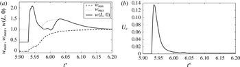
Diagram of states for
 $\mathit{Re}=4000$
, axisymmetric flow when active flow control is applied, Lamb–Oseen vortex,
 $b=4$
. Dashed lines represent equilibrium natural states according to weakly nonlinear theory. Arrows represent controlled flow evolution at certain swirls from initial states (represented by the circles) to the almost columnar states (represented by the solid lines).

The details of another example of the controlled flow at
 $\mathit{Re}=4000$
and
 ${\it\omega}=0.86$
are described in figures 24 and 25. The initial state is the flow state at
 $t_{0}=1280$
(
 $t^{\ast }=5.93$
) shown in figure 10( f). The control parameters are
 ${\it\gamma}=-4$
and
 $T_{s}=1.5$
. The initial breakdown zone (figure 24
a) is first diffused by much flow injection (figure 24
b–d), pushed out along the centreline (figure 24
e), before the flow returns to an almost columnar state (figure 24
f). The maximum, minimum and outlet values of the axial velocity also decay, with oscillations at the beginning and exponential decay at the end to a value near unity (figure 25
a). The control injection command (figure 25
b) increases to a maximum value,
 $U_{c}=0.135$
(
 ${\dot{m}}_{in}=1.62$
,
 $C_{{\it\mu}}=0.219$
) at
 $t=1282$
(
 $t^{\ast }=5.937$
) and then decays to same constant value as above, 0.0017. An initial greater injection is needed to overcome the larger breakdown zone at the higher swirl. The non-dimensional control response time is
 ${\rm\Delta}t\sim 60$
.
Similar controlled flow dynamics and elimination of the vortex breakdown states are found for the entire range of swirl between
 ${\it\omega}_{0{\it\nu}}=0.748$
and
 ${\it\omega}=0.87$
. The control gain must become more negative as the swirl is increased in this range to achieve effective control. These computations demonstrate that an almost columnar controlled state can be established for swirl levels above
 ${\it\omega}_{0{\it\nu}}$
where breakdown exists in the natural case. This is represented in figure 26 by the arrows pointing from the natural breakdown states to the almost columnar states. A branch of almost columnar states with a wide basin of attraction is established by the active feedback flow control for the range of swirl from 0 up to 0.87, which does not exist at all in the natural flow. Using the active feedback control law, the envelope of operation of stable columnar states is increased up to 7 % above
 ${\it\omega}_{1{\it\nu}}$
and 17 % above
 ${\it\omega}_{0{\it\nu}}$
, while no stable breakdown can exist in this range of swirl. Note, however, that the controller must remain active all the time to maintain a stable columnar state.
7. Conclusions
An active feedback flow control theory of the vortex breakdown process in incompressible axisymmetric swirling flows in a finite-length straight circular pipe is developed. Flow injection distributed along the pipe wall is used as the controller. The flow is subjected to non-periodic inlet and outlet conditions. At the inlet, the radial profiles of the axial velocity, circumferential velocity and azimuthal vorticity are prescribed, while, at the outlet, a no-radial-velocity state is set. The flow has a degree of freedom to develop radial velocity at the inlet as perturbations propagate in the pipe. This model may represent the nature of axisymmetric swirling flows in experimental apparatus used to study the vortex breakdown phenomenon. Two simulation codes were used to compute the flow dynamics at various swirl levels in both the inviscid-limit and viscous flow cases. In addition, a long-wave asymptotic analysis, which involves a rescaling of the axial distance along the pipe and the time at near-critical swirl ratios, results in a reduced-order nonlinear model problem for the study of the dynamics and control in a pipe (§ 3). In § 4, the weakly nonlinear model and the simulation codes are used, together with Wang & Rusak’s (Reference Wang and Rusak1997a
) theory of vortex breakdown, to study the dynamics of swirling flows as it is related to steady-state solutions and the stability characteristics of these solutions. The theoretical predictions and numerical simulation results agree with one another. This combined theoretical–numerical approach provides the detailed bifurcation diagrams of axisymmetric states for both the inviscid and high-
 $\mathit{Re}$
flow cases (see figures 1 and 8, respectively). The results shed light on the importance of the two critical swirls,
 ${\it\omega}_{0}$
and
 ${\it\omega}_{1}$
in the inviscid flow case, and
 ${\it\omega}_{0{\it\nu}}$
and
 ${\it\omega}_{1{\it\nu}}$
in the high-
 $\mathit{Re}$
flow case. The results also clarify the various dynamical situations that may appear in response to a variety of initial conditions. Unstable equilibrium states may be local attractors of flow dynamics and complicate the flow evolution.
An energy identity is developed in § 5 that adds insight into the interaction mechanisms that govern the natural swirling flow. It is found that there exists a feed-forward mechanism between the evolution of perturbations in the bulk and the development of the inlet radial velocity, which leads to the growth of a global mode of perturbations when the swirl level is above
 ${\it\omega}_{0}$
or
 ${\it\omega}_{1}$
. This is crucial information of flow physics in the design of a control methodology. The energy identity suggests an active feedback control law (5.2) that relates the flow wall injection to the evolving maximum radial velocity at the inlet. Essentially, the feedback control cuts the natural feed-forward mechanism of the breakdown process.
Computed examples in § 6 of the controlled flow dynamics based on the full axisymmetric Euler and Navier–Stokes formulations at various swirl levels demonstrate for the first time that applying the proposed feedback control law during flow evolution is successful in eliminating the breakdown states and inducing flow stabilization on an almost columnar state. Figures 4 and 14, figures 5 and 16, figures 3 and 19, and figures 9 and 13 provide representative examples of the evolution of a disturbance on a columnar flow to a vortex breakdown state, and then its elimination and return to a columnar state once active feedback flow control is applied. This is achieved for a wide range of swirl up to at least 30 % above
 ${\it\omega}_{1}$
and 56 % above
 ${\it\omega}_{0}$
in the inviscid-limit flow case. Likewise, it is achieved for a range of swirl up to at least 7 % above
 ${\it\omega}_{1{\it\nu}}$
and 17 % above
 ${\it\omega}_{0{\it\nu}}$
for
 $\mathit{Re}=4000$
flows. Specifically, in the case of high-
 $\mathit{Re}$
flows, the control approach establishes a branch of columnar states for all swirl levels studied where in the natural flow dynamics no such states even exist. The control approach is robust in terms of swirl and establishes a wide basin of attraction around the columnar states (see the bifurcation diagrams in figures 20 and 26). This basin is wide enough to include even the natural breakdown states that are diffused by the control law.
The present theory is limited to the control of axisymmetric flows in pipes where the wall boundary layer is thin and attached and does not interact with the flow in the bulk. Extending the theory to study the linear and nonlinear stability of swirling flows in pipes to three-dimensional perturbations and the possible control of these perturbations remains a grand challenge. Such a theory may explain the properties of high-
 $\mathit{Re}$
turbulent flow states documented in the seminal experiments of Novak & Sarpkaya (Reference Novak and Sarpkaya2000). Moreover, a study of the interaction between the wall boundary layer and the swirling flows in pipes will also shed light on situations where the boundary layer separates and complicates the flow dynamics and structure.
Appendix A
The various perturbation functions in the assumed asymptotic equations (3.2) satisfy the following boundary conditions for all time
 $t^{\ast }\geqslant 0$
:
 $$\begin{eqnarray}\left.\begin{array}{@{}c@{}}{\it\psi}_{1}(0,y,t^{\ast })=\displaystyle {\it\psi}_{1XX}(0,y,t^{\ast })=K_{1}(0,y,t^{\ast })=0\quad \text{for }0\leqslant y\leqslant 1/2,\\ {\it\psi}_{2}(0,y,t^{\ast })=\displaystyle {\it\psi}_{2XX}(0,y,t^{\ast })=K_{2}(0,y,t^{\ast })=0\quad \text{for }0\leqslant y\leqslant 1/2,\\ {\it\psi}_{1X}(1,y,t^{\ast })=\displaystyle {\it\psi}_{2X}(1,y,t^{\ast })=0\quad \text{for }0\leqslant y\leqslant 1/2,\\ {\it\psi}_{1}(X,0,t^{\ast })=\displaystyle K_{1}(X,0,t^{\ast })=0\quad \text{for }0\leqslant X\leqslant 1,\\ {\it\psi}_{2}(X,0,t^{\ast })=\displaystyle K_{2}(X,0,t^{\ast })=0\quad \text{for }0\leqslant X\leqslant 1,\\ {\it\psi}_{1}(X,1/2,t^{\ast })=\displaystyle K_{1}(X,1/2,t^{\ast })=0\quad \text{for }0\leqslant X\leqslant 1,\\ {\it\epsilon}_{2}{\it\psi}_{2X}(X,1/2,t^{\ast })={\it\epsilon}_{1}^{2}U_{c}^{\ast }(X,t^{\ast }),\\ K_{2}(X,1/2,t^{\ast })=0\quad \text{for }0\leqslant X\leqslant 1.\end{array}\right\}\end{eqnarray}$$
From the assumed asymptotic expansions (3.2) and the relationship between the reduced azimuthal vorticity and the streamfunction we find that
 $$\begin{eqnarray}{\it\chi}_{0}=-{\it\psi}_{0yy},\quad {\it\chi}_{1}=-{\it\psi}_{1yy},\quad {\it\epsilon}_{2}{\it\chi}_{2}=-{\it\epsilon}_{2}{\it\psi}_{2yy}-{\it\epsilon}_{1}^{2}\frac{{\it\psi}_{1XX}}{2y}.\end{eqnarray}$$
In addition, from the circulation equation (2.1), we have at the leading order
 $O({\it\epsilon}_{1}^{3/2})$
,
 $$\begin{eqnarray}K_{1}(X,y,t^{\ast })={\it\omega}_{B}\frac{K_{0y}}{{\it\psi}_{0y}}{\it\psi}_{1}(X,y,t^{\ast }).\end{eqnarray}$$
At orders
 ${\it\epsilon}_{1}^{1/2}{\it\epsilon}_{2}$
,
 ${\it\epsilon}_{1}^{5/2}$
and
 ${\it\epsilon}_{1}^{3/2}{\rm\Delta}{\it\omega}$
, the circulation equation (2.1) yields
 $$\begin{eqnarray}{\it\epsilon}_{2}K_{2X}=\frac{1}{{\it\psi}_{0y}}[{\it\epsilon}_{2}{\it\omega}_{B}K_{0y}{\it\psi}_{2X}-{\it\epsilon}_{1}^{2}(K_{1t^{\ast }}+{\it\psi}_{1y}K_{1X}-{\it\psi}_{1X}K_{1y})+{\it\epsilon}_{1}{\rm\Delta}{\it\omega}K_{0y}{\it\psi}_{1X}+2{\it\epsilon}_{1}^{2}{\it\kappa}_{2}{\it\omega}_{B}yK_{0yy}].\end{eqnarray}$$
From the reduced azimuthal vorticity equation in (2.1), we have at order
 $O({\it\epsilon}_{1}^{3/2})$
,
 $$\begin{eqnarray}{\it\psi}_{0y}{\it\chi}_{1X}-{\it\chi}_{0y}{\it\psi}_{1X}=\frac{1}{2y^{2}}{\it\omega}_{B}K_{0}K_{1X}.\end{eqnarray}$$
Using the equations for
 ${\it\chi}_{1}$
from (A 2) and for
 $K_{1X}$
from (A 3), we have
 $$\begin{eqnarray}{\it\psi}_{0y}{\it\psi}_{1yyX}+{\it\chi}_{0y}{\it\psi}_{1X}+\frac{{\it\omega}_{B}^{2}K_{0}K_{0y}}{2y^{2}{\it\psi}_{0y}}{\it\psi}_{1X}=0.\end{eqnarray}$$
Integrating (A 6) with respect to
 $X$
and using the inlet condition for
 ${\it\psi}_{1}$
from (A 1) we find
 $$\begin{eqnarray}{\it\psi}_{1yy}+\left(\frac{{\it\chi}_{0y}}{{\it\psi}_{0y}}+\frac{{\it\omega}_{B}^{2}K_{0}K_{0y}}{2y^{2}{\it\psi}_{0y}^{2}}\right){\it\psi}_{1}=0.\end{eqnarray}$$
The solution of (A 7) is
 ${\it\psi}_{1}(X,y,t^{\ast })={\it\phi}_{1}(y)A(X,t^{\ast })$
, where the function
 ${\it\phi}_{1}(y)$
is described by Benjamin’s (Reference Benjamin1962) eigenvalue problem:
 $$\begin{eqnarray}\left.\begin{array}{@{}c@{}}\displaystyle {\it\phi}_{1yy}+\left(\frac{{\it\chi}_{0y}}{{\it\psi}_{0y}}+\frac{{\it\omega}_{B}^{2}K_{0}K_{0y}}{2y^{2}{\it\psi}_{0y}^{2}}\right){\it\phi}_{1}=0,\\ \displaystyle {\it\phi}_{1}(0)={\it\phi}_{1}(1/2)=0.\end{array}\right\}\end{eqnarray}$$
The first eigenvalue of the problem (A 8) is defined as
 ${\it\omega}_{B}$
and the corresponding eigenfunction is
 ${\it\phi}_{1}={\it\phi}_{B}(y)$
. In solving (A 8) we assume
 ${\it\phi}_{By}(0)=1$
as the scaling of the linear eigenvalue problem. Then, the centreline axial velocity is given by
 ${\it\psi}_{y}(X,0,t^{\ast })={\it\psi}_{0y}(0)+{\it\epsilon}_{1}A(X,t^{\ast })+\cdots$
. Also, the circulation perturbation is
 $K_{1}(X,y,t^{\ast })={\it\omega}_{B}(K_{0y}/{\it\psi}_{0y}){\it\phi}_{B}(y)A(X,t^{\ast })$
and the reduced azimuthal vorticity perturbations are given by
 ${\it\chi}_{1}(X,y,t^{\ast })=-{\it\phi}_{Byy}(y)A(X,t^{\ast })$
and
 ${\it\epsilon}_{2}{\it\chi}_{2}(X,y,t^{\ast })=-{\it\epsilon}_{2}{\it\psi}_{2yy}-{\it\epsilon}_{1}^{2}{\it\phi}_{B}/2yA_{XX}$
.
To solve the function
 $A(X,t^{\ast })$
, we analyse the azimuthal vorticity equation in (2.1) at orders
 ${\it\epsilon}_{1}^{1/2}{\it\epsilon}_{2}$
,
 ${\it\epsilon}_{1}^{5/2}$
and
 ${\it\epsilon}_{1}^{3/2}{\rm\Delta}{\it\omega}$
. We find that
 $$\begin{eqnarray}\displaystyle & & \displaystyle {\it\epsilon}_{1}^{1/2}{\it\epsilon}_{2}({\it\psi}_{0y}{\it\chi}_{2X}-{\it\chi}_{0y}{\it\psi}_{2X})+{\it\epsilon}_{1}^{5/2}({\it\chi}_{1t^{\ast }}+{\it\phi}_{By}A{\it\chi}_{1X}-{\it\phi}_{B}A_{X}{\it\chi}_{1y})\nonumber\\ \displaystyle & & \displaystyle \quad ={\it\epsilon}_{1}^{1/2}{\it\epsilon}_{2}{\it\omega}_{B}\frac{K_{0}K_{2X}}{2y^{2}}+{\it\epsilon}_{1}^{5/2}\frac{K_{1}K_{1X}}{2y^{2}}+{\it\epsilon}_{1}^{3/2}{\rm\Delta}{\it\omega}\frac{K_{0}K_{1X}}{2y^{2}}+2{\it\epsilon}_{1}^{5/2}{\it\kappa}_{2}({\it\chi}_{0yy}+2{\it\chi}_{0y}).\end{eqnarray}$$
Using (A 2), (A 4) and (A 8) we find
 $$\begin{eqnarray}\displaystyle & & \displaystyle {\it\epsilon}_{2}\left[{\it\psi}_{2yyX}+\left(\frac{{\it\chi}_{0y}}{{\it\psi}_{0y}}+\frac{{\it\omega}_{B}^{2}K_{0}K_{0y}}{2y^{2}{\it\psi}_{0y}^{2}}\right){\it\psi}_{2X}\right]+2{\it\epsilon}_{1}{\rm\Delta}{\it\omega}\frac{{\it\omega}_{B}K_{0}K_{0y}}{2y^{2}{\it\psi}_{0y}^{2}}{\it\phi}_{B}A_{X}\nonumber\\ \displaystyle & & \displaystyle \qquad \quad \quad +\,{\it\epsilon}_{1}^{2}\left[-\!\left(\frac{{\it\chi}_{0y}}{{\it\psi}_{0y}^{2}}+\frac{{\it\omega}_{B}^{2}K_{0}K_{0y}}{y^{2}{\it\psi}_{0y}^{3}}\right){\it\phi}_{B}A_{t^{\ast }}+\frac{{\it\phi}_{B}}{2y}A_{XXX}\right.\nonumber\\ \displaystyle & & \displaystyle \qquad \quad \quad \left.+\left(\frac{1}{{\it\psi}_{0y}}\left(\frac{{\it\chi}_{0y}}{{\it\psi}_{0y}}+\frac{{\it\omega}_{B}^{2}K_{0}K_{0y}}{2y^{2}{\it\psi}_{0y}^{2}}\right)_{y}+\frac{{\it\omega}_{B}^{2}K_{0y}^{2}}{2y^{2}{\it\psi}_{0y}^{3}}+\frac{{\it\omega}_{B}^{2}K_{0}}{2y^{2}{\it\psi}_{0y}}\left(\frac{K_{0y}}{{\it\psi}_{0y}}\right)_{y}\right){\it\phi}_{B}^{2}AA_{X}\right]\nonumber\\ \displaystyle & & \displaystyle \qquad \quad \quad +\,{\it\epsilon}_{1}^{2}{\it\kappa}_{2}\left[\frac{2}{{\it\psi}_{0y}}(y{\it\chi}_{0yy}+2{\it\chi}_{0y})+\frac{{\it\omega}_{B}^{2}K_{0}K_{0yy}}{y{\it\psi}_{0y}^{2}}\right]=0.\end{eqnarray}$$
Multiplying (A 10) by
 ${\it\phi}_{B}(y)$
, integrating with respect to
 $y$
from 0 to 1∕2, integrating the terms with
 ${\it\psi}_{2}$
by parts and using the centreline and wall conditions for
 ${\it\psi}_{2}$
in (A 1), we find the equation (3.3) and coefficients (3.5) for computing
 $A(X,t^{\ast })$
. The boundary conditions (3.6) for
 $A$
are derived from the inlet and outlet conditions for
 ${\it\psi}_{1}$
in (A 1).