
1. Introduction
Inertial and gravito-inertial waves are important phenomena in rotating stars and planets. Wave propagation can transport momentum and energy, therefore it may have significant impact on stellar or planetary structures and evolutions. For example, internal-gravity waves (IGWs) play an important role in transporting angular momentum when they propagate in the radiative zones of stars (Belkacem et al. Reference Belkacem, Marques, Goupil, Sonoi, Ouazzani, Dupret, Mathis, Mosser and Grosjean2015a, Reference Belkacem, Marques, Goupil, Sonoi, Ouazzani, Dupret, Mathis, Mosser and Grosjean; Pinçon et al. Reference Pinçon, Belkacem, Goupil and Marques2017; Aerts, Mathis & Rogers Reference Aerts, Mathis and Rogers2019). Study reveals that IGWs can reduce differential rotation in low mass stars in a short time scale (Rogers et al. Reference Rogers, Lin, McElwaine and Lau2013). They can also explain the misalignment of exoplanets around hot stars (Rogers, Lin & Lau Reference Rogers, Lin and Lau2012). Apart from IGWs, inertial waves can also be generated in rotating planets (Ogilvie & Lin Reference Ogilvie and Lin2004; Wu Reference Wu2005a; Goodman & Lackner Reference Goodman and Lackner2009). It has been found that the resonantly excited inertial wave has an important impact on the tidal dissipation in planets (Wu Reference Wu2005b).
It is quite common for a star or planet to have a multi-layer structure. For example, a superadiabatic region embedded in radiative layers may appear in a neutron star's atmosphere because of the ionization of  $^{56}$Fe (Miralles, Urpin & Van Riper Reference Miralles, Urpin and Van Riper1997). Waves generated by convective motions can transport energy to the chromosphere and corona, which may drive the stellar wind. In A-type stars, it is possible for them to have complex internal structures with multiple convection zones. Interaction between these convective zones has important implications in material mixing and energy transport (Silvers & Proctor Reference Silvers and Proctor2007). It is also known that layered semiconvection zones can be formed in stars in the process of double-diffusive convection (Mirouh et al. Reference Mirouh, Garaud, Stellmach, Traxler and Wood2012; Wood, Garaud & Stellmach Reference Wood, Garaud and Stellmach2013; Garaud Reference Garaud2018). For main sequence stars slightly more massive than the Sun, it has been found that the efficiency of mixing in layered semiconvection zones sensitively depends on the layer height (Moore & Garaud Reference Moore and Garaud2016). Layered convection zones also exist in planets. Multi-layer structure has been detected in a region several hundred metres below the surface of the Arctic ocean (Rainville & Winsor Reference Rainville and Winsor2008). Observation shows that a shallow convective region is embedded within stable layers in the atmosphere of Venus (Tellmann et al. Reference Tellmann, Pätzold, Häusler, Bird and Tyler2009). Seismology on Saturn's ring reveals the layered stable stratification in the deep interior of Saturn (Fuller Reference Fuller2014). If stable stratification exists in the deep interior of Saturn, then the g-mode can be excited in this region. Layered convection probably also exists in Jupiter. A new model with layered convection on Jupiter and Saturn indicates that the heavy elements in our Jovian planets are more enriched than previously thought (Leconte & Chabrier Reference Leconte and Chabrier2012). One interesting question is whether g-mode waves can transmit to the surface, so that they can be possibly captured by observations.
Wave can transmit in a double barrier system through a tunnelling process. Sutherland & Yewchuk (Reference Sutherland and Yewchuk2004) studied transmissions of internal wave tunnelling for both  $N^2$-barrier (low
 $N^2$ layer embedded in high
 $N^2$ layers and horizontal mean density varies continuously) and mixed-
 $N^2$ (low
 $N^2$ layer embedded in high
 $N^2$ layers but horizontal mean density varies discontinuously) profiles, where
 $N^2$ is the square of the buoyancy frequency. They found that wave transmission can be efficient for resonant transfers. Sutherland (Reference Sutherland2016) investigated the transmission of internal waves in a multi-layer structure separated by discontinuous density jumps. He deduced an analytical solution for wave transmission when the steps are evenly spaced, and predicted that waves with longer horizontal wavelength and larger frequencies are more likely to transmit in the density staircase profile. Sutherland (Reference Sutherland1996) considered wave propagation in profiles of piecewise linear stratified layers with weaker stratification at the top. He discovered that large-amplitude IGWs incident from the bottom can partially transmit energy into the top layer by the generation of a lower frequency wave packet. Resonant tunnelling of electron transmission in double barriers is familiar in quantum physics, and has been widely used in designing semiconductor devices, such as tunnel diodes, NPN (negative–positive–negative) and PNP (positive–negative–positive) triodes (Singh Reference Singh2010). In comparison with tunnelling of electron transmission, it is expected that resonant tunnelling also occurs for wave transmission in multi-layer structures.
Wave transmission in a three-layer structure with rotational effects has been considered by Gerkema & Exarchou (Reference Gerkema and Exarchou2008). They compared wave transmissions with and without traditional approximations (the horizontal component of rotation is neglected when the traditional approximation is adopted on an f-plane). For a three-layer structure with a convective layer embedded in strongly stratified layers, waves cannot survive in both convective and stratified layers under the traditional approximation, while it is possible if non-traditional effects are taken into account. They also showed that near-inertial waves are always transmitted efficiently for stratified layers of any stratification. Belyaev, Quataert & Fuller (Reference Belyaev, Quataert and Fuller2015) investigated the free modes of a multi-layer structure wave propagation with rotation at the poles and equator. They found that g-modes with vertical wavelengths smaller than the layer thickness are evanescent. André, Barker & Mathis (Reference André, Barker and Mathis2017) studied the effects of rotation on free modes and wave transmission in a multi-layer structure at a general latitude. They showed that transmission can be efficient when the incident wave is resonant with waves in adjacent layers with half-wavelengths equal to the layer depth. They also discovered that perfect wave transmission can be obtained at the critical latitude. Pontin et al. (Reference Pontin, Barker, Hollerbach, André and Mathis2020) studied the wave propagation in semiconvective regions of non-rotating giant planets in the full sphere. They found that wave transmissions are efficient for very large wavelength waves.
In previous works (Wei Reference Wei2020a,Reference Weib; Cai, Yu & Wei Reference Cai, Yu and Wei2021), we have discussed the efficiency of inertial and gravito-inertial wave transmissions in a two-layer structure on f-planes. For a step stratification near the interface, we have found that the transmission generally is not efficient if the stable layer is strongly stratified. In this paper, we investigate the wave transmission in a multi-layer structure on f-planes. Specifically, we will consider wave transmissions via two different mechanisms: wave propagation and wave tunnelling. We find that wave transmission in a multi-layer structure can be significantly different from that in a two-layer structure.
2. The model and result
For the Boussinesq flow in a rotating f-plane, the hydrodynamic equations can be synthesized into a partial differential equation on vertical velocity  $w$ (Gerkema & Shrira Reference Gerkema and Shrira2005b)
 \begin{equation} \nabla^2 w_{tt}+(\boldsymbol{f}\boldsymbol{\cdot} \boldsymbol{\nabla})^2 w +N^2(z) \nabla_{h}^2 w=0, \end{equation}
where  $\boldsymbol {f}=(0,\tilde {f},f)$ is the vector of Coriolis parameters,
 $N^2$ is the square of the buoyancy frequency,
 $\nabla ^2$ is Laplacian operator,
 $\nabla _{h}^2$ is its horizontal component and the subscript
 $t$ represents taking the derivative with respect to time. By letting
 $w=W(\chi ,z)\exp (-\textrm {i}\sigma t)$, Gerkema & Shrira (Reference Gerkema and Shrira2005b) found (2.1) can be transformed into the following equation:
 \begin{equation} AW_{\chi\chi}+2BW_{\chi z}+CW_{zz}=0, \end{equation}
where  $A=\tilde {f}_{s}^2-\sigma ^2+N^2,\ {\rm where}\ \sigma\ {\rm is}\ {\rm the}\ {\rm time}\ {\rm frequency},$
 $B=f\tilde {f}_{s}, C=f^2-\sigma ^2, \tilde {f}_{s}=\tilde {f}\sin \alpha$, where
 $\alpha$ is the angle between the direction of the plane wave and the x-direction, and
 $\chi$ is a variable satisfying
 $x=\chi \cos \alpha$ and
 $y=\chi \sin \alpha$. Here,
 $x,y,z$ are the west–east, south–north and vertical directions, respectively. We define
 $A_{0}=\tilde {f}_{s}^2-\sigma ^2$, so that
 $A=A_{0}+N^2$. Taking advantage of plane waves and assuming
 $W(\chi ,z)=\psi (z)\exp (\textrm {i} \delta z+{\rm i}k\chi )$, Gerkema & Shrira (Reference Gerkema and Shrira2005b) have further simplified (2.2) into an equation of wave amplitude
 $\psi$
 \begin{equation} \psi_{zz}+k^2 \frac{B^2-AC}{C^2}\psi=0, \end{equation}
where  $\delta =-kB/C$, with k is the horizontal wavenumber. A wave solution then requires
 $B^2-AC>0$, and the squared wavenumber is
 $r^2=k^2(B^2-AC)/C^2$. If
 $B^2-AC>0$, then
 $r$ is a real number and the flow propagates along the vertical direction as a wave. On the other hand, if
 $B^2-AC<0$, then
 $r$ is a pure imaginary number, and the wave amplitude increases or decreases exponentially.
In previous works (Wei Reference Wei2020a; Cai et al. Reference Cai, Yu and Wei2021) we have investigated wave transmission in a two-layer setting f-plane (a convective layer with  $N^2=0$ and a convectively stable layer with
 $N^2>0$). Note that the actual
 $N^2$ should be smaller than zero. In real stars, however, convection is generally efficient in transporting energy, leading to a nearly adiabatic thermal structure. Thus,
 $N^2$ values in convective layers are only slightly smaller than zero. For this reason, we choose
 $N^2=0$ for convective layers in our model. In this paper, we extend previous works to study the wave transmission in a multi-layer setting f-plane. At this beginning stage, we use an ideal model by assuming
 $N^2$ is constant in each layer. In all convective layers,
 $N^2$ values are equal and set to zero. In stable layers,
 $N^2$ values can be different but remain constant in each layer, with minimum and maximum values of
 $N_{min}^2$ and
 $N_{max}^2$, respectively. We also assume that the propagation of inertial waves is not affected by convection. The validity of this assumption requires that the nonlinear and viscous effects are small. Detailed discussion on relations and differences between convection and inertial waves can be found in Zhang & Liao (Reference Zhang and Liao2017). Here, we attempt to use a toy model to gain some insights into wave transmissions in a multi-layer structure. Cai et al. (Reference Cai, Yu and Wei2021) have made a detailed discussion on the frequency domain of wave solutions. If a wave is to survive in a convective layer, then the following condition must be satisfied:
 \begin{equation} \varDelta_{c}=B^2-A_{0}C>0. \end{equation}
Similarly, the condition for wave propagation in a stable layer is
 \begin{equation} \varDelta_{s}=B^2-A_{0}C-N_{s}^2C>0. \end{equation}
Let us define
 \begin{gather} \sigma_{1,4}^2=\left[(f^2+\tilde{f}_{s}^2)\mp \sqrt{(f^2+\tilde{f}_{s}^2)^2}\right]\Bigg/2, \end{gather}
 \begin{gather}\sigma_{2,5}^2=\left[(f^2+\tilde{f}_{s}^2+N_{min}^2)\mp \sqrt{(f^2+\tilde{f}_{s}^2+N_{min}^2)^2-4N_{min}^2\, f^2}\right]\Bigg/2, \end{gather}
 \begin{gather}\sigma_{3,6}^2=\left[(f^2+\tilde{f}_{s}^2+N_{max}^2)\mp \sqrt{(f^2+\tilde{f}_{s}^2+N_{max}^2)^2-4N_{max}^2\, f^2}\right]\Bigg/2, \end{gather}
where  $\sigma _{1}=0$ and
 $\sigma _{4}=f^2+\tilde {f}_{s}^2$ are roots of
 $\varDelta _{c}=0$, and
 $\sigma _{2,5}$ and
 $\sigma _{3,6}$ are roots of
 $\varDelta _{s}=0$ when
 $N_{s}^2=N_{min}^2$ and
 $N_{s}^2=N_{max}^2$, respectively. It is not difficult to verify that the relation
 $\sigma _{1}\leq \sigma _{2}\leq \sigma _{3}\leq \sigma _{4}\leq \sigma _{5}\leq \sigma _{6}$ holds.
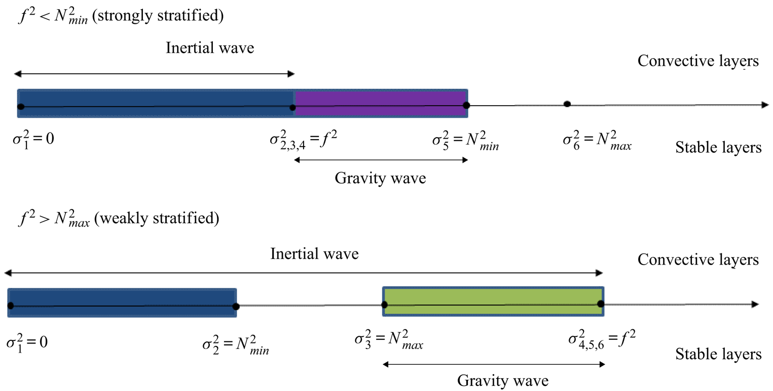
Figure 1(a) shows the frequency ranges for different waves in convectively unstable and stable layers, respectively. In the green region ( $\sigma _{3}^2<\sigma ^2<\sigma _{4}^2$), waves can survive and propagate in both convective and stable layers, and we term this phenomenon ‘wave propagation’. In the blue region
 $\sigma _{1}^2<\sigma ^2<\sigma _{2}^2$, inertial waves can survive in convective layers but gravity waves cannot survive in stable layers. Inertial waves can transmit through a tunnelling process, and we term this phenomenon ‘tunnelling of inertial wave’. In the purple region
 $\sigma _{4}^2<\sigma ^2<\sigma _{5}^2$, gravity waves can survive in stable layers but inertial waves cannot survive in convective layers. Similarly, gravity waves can transmit through a tunnelling process, and we term this phenomenon ‘tunnelling of gravity wave’.
Plot of wave propagations in multiple convectively stable and unstable layers. Wave frequency ranges are shown above and below the middle arrow for convective and stable layers, respectively. Wave propagation occurs in the green region, tunnelling of inertial wave occurs in the blue region and tunnelling of gravity wave occurs in the purple region.

In Cai et al. (Reference Cai, Yu and Wei2021), we have also deduced that  $c_{p0}c_{g}$ has the same sign as
 $C$, where
 $c_{p0}$ is the modified vertical component of wave phase velocity and
 $c_{g}$ is the vertical component of the wave group velocity. The vertical component of phase velocity should be computed by
 $\sigma /(\delta \pm r)$, but here the tilted effect is excluded in the modified one
 $c_{p0}=\sigma /(\pm r)$. Since the wave direction of energy propagation is determined by
 $c_{g}$, a proper choice of wave direction depends on whether the wave is sub-inertial (
 $C>0$) or super-inertial (
 $C<0$).
2.1. Wave propagation
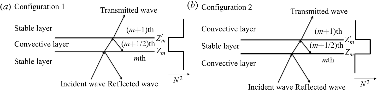
In this section, we discuss wave propagation in both convective and stable layers, which requires that the frequency is in the range  $\sigma _{3}^2<\sigma ^2<\sigma _{4}^2$. We consider different configurations with different combinations of layer structures and wave directions. The incident wave can propagate from the convective layer or stable layer, and the wave propagating direction can be upward or downward. Since up/down symmetry holds in Boussinesq flow, it is sufficient to discuss the cases with waves incident from the bottom. The cases with waves incident from the top can be inferred from the up/down symmetry. Figure 2 shows plots of the two configurations in a three-layer setting f-plane. Structures with more layers are similar. At each interface, two boundary conditions have to be satisfied: the vertical velocity is continuous; and the first derivative of the vertical velocity is continuous (Wei Reference Wei2020a; Cai et al. Reference Cai, Yu and Wei2021).
Plots of wave propagations in multiple convectively stable and unstable layers. (a) The convective layer is embedded between two stable layers. (b) The stable layer is embedded between two convective layers. Structure of the square of buoyancy frequency  $N^2$ is shown by the side.

We start the discussion on configuration 1 (figure 2a), and assume that the number of interfaces is even. We label the convective layer with the half-grid number ( $m+1/2$). For the
 $(m+1/2)$th convective layer, we label its lower and upper neighbouring stable layers the
 $m$th and
 $(m+1)$th stable layers, respectively; and we set the locations of the lower and upper interfaces at
 $z_{m}$ and
 $z'_{m}$, respectively. The thickness of the convective layer is
 ${\rm \Delta} z'_{m}=z'_{m}-z_{m}$, and the thickness of the stable layer is
 ${\rm \Delta} z_{m}=z_{m}-z'_{m-1}$. For the
 $m$th stable layer, we define its wavenumber square as
 $s_{m}^2=k^2(B^2-A_{0}C-N_{m}^2 C)/C^2$. For the
 $(m+1/2)$th convective layer, we define its wavenumber square as
 $q_{m}^2=k^2(B^2-A_{0}C)/C^2$. In this paper, we only consider a simple case, in which the square of the buoyancy frequency is a constant within each convective or stable layer. Under this assumption, we find wave solutions in the
 $m$th stable layer
 \begin{equation} \psi_{m}(z)=a_{m}\ \textrm{e}^{-\textrm{i}s_{m}z}+b_{m}\ \textrm{e}^{\textrm{i}s_{m}z}, \quad z\in (z'_{m-1},z_{m}),\end{equation}
and in the  $(m+1/2)$th convective layer
 \begin{equation} \psi_{m+1/2}(z)=c_{m}\ \textrm{e}^{-\textrm{i}q_{m}z}+d_{m}\ \textrm{e}^{-\textrm{i}q_{m}z}, \quad z\in (z_{m},z'_{m}),\end{equation}
respectively. As mentioned earlier,  $c_{p0}c_{g}$ has the same sign as
 $C$, from which we conclude
 $Sgn(c_{g})=Sgn(C)Sgn(c_{p0})$. The sign of the modified vertical phase velocity
 $c_{p0}$ is determined by the sign of
 $q_{m}$ or
 $s_{m}$. If
 $Sgn(C)Sgn(c_{p0})>0$, then the vertical group velocity
 $c_{g}$ is positive (wave direction is outgoing); on the other hand, if
 $Sgn(C)Sgn(c_{p0})<0$, then
 $c_{g}$ is negative (wave direction is incoming). We choose
 $q_{m}>0$ for
 $C>0$, and
 $q_{m}<0$ for
 $C<0$. For either case, the waves with wavenumbers
 $q_{m}$ and
 $s_{m}$ are outgoing waves, and the waves with wavenumbers
 $-q_{m}$ and
 $-s_{m}$ are incoming waves. Note that all
 $q_{m}$ and
 $s_{m}$ always have the same sign. Matching the boundary conditions at the interfaces
 $z_{m}$ and
 $z'_{m}$, we have
 \begin{gather} a_{m}\ \textrm{e}^{-\textrm{i}s_{m}z_{m}}+b_{m}\ \textrm{e}^{\textrm{i}s_{m}z_{m}} =c_{m}\ \textrm{e}^{-\textrm{i}q_{m}z_{m}}+d_{m}\ \textrm{e}^{\textrm{i}q_{m}z_{m}}, \end{gather}
 \begin{gather}({-}a_{m}\ \textrm{e}^{-\textrm{i}s_{m}z_{m}}+b_{m}\ \textrm{e}^{\textrm{i}s_{m}z_{m}})s_{m} =({-}c_{m}\ \textrm{e}^{-\textrm{i}q_{m}z_{m}}+d_{m}\ \textrm{e}^{\textrm{i}q_{m}z_{m}})q_{m}, \end{gather}
 \begin{gather}c_{m}\ \textrm{e}^{-\textrm{i}q_{m}z'_{m}}+d_{m}\ \textrm{e}^{\textrm{i}q_{m}z'_{m}} =a_{m+1}\ \textrm{e}^{-\textrm{i}s_{m+1}z'_{m}}+b_{m+1}\ \textrm{e}^{\textrm{i}s_{m+1}z'_{m}}, \end{gather}
 \begin{gather}({-}c_{m}\ \textrm{e}^{-\textrm{i}q_{m}z'_{m}}+d_{m}\ \textrm{e}^{\textrm{i}q_{m}z'_{m}})q_{m} =({-}a_{m+1}\ \textrm{e}^{-\textrm{i}s_{m+1}z'_{m}}+b_{m+1}\ \textrm{e}^{\textrm{i}s_{m+1}z'_{m}}) s_{m+1}. \end{gather}
Wave propagations in multi-layer structures have been investigated in Belyaev et al. (Reference Belyaev, Quataert and Fuller2015), André et al. (Reference André, Barker and Mathis2017) and Pontin et al. (Reference Pontin, Barker, Hollerbach, André and Mathis2020). A useful approach to modelling wave propagations in a multi-layer structure is to build on relations of wave amplitudes by transfer matrices. From the above boundary conditions, we can derive the following transfer relations (see Appendix A):
 \begin{equation} \left[ \begin{array}{@{}c@{}} a_{m}\\ b_{m} \end{array} \right]=\boldsymbol{\mathsf{T}}_{m,m+1} \left[ \begin{array}{@{}c@{}} a_{m+1}\\ b_{m+1} \end{array} \right] =\left[\begin{array}{@{}cc@{}} \hat{{\mathsf{T}}}_{11} & \hat{{\mathsf{T}}}_{12} \\ \hat{{\mathsf{T}}}_{21} & \hat{{\mathsf{T}}}_{22} \end{array} \right] \left[ \begin{array}{@{}c@{}} a_{m+1}\\ b_{m+1} \end{array} \right],\end{equation}
where
 \begin{align} \hat{{\mathsf{T}}}_{11}&=\frac{1}{4}\ \textrm{e}^{\textrm{i}(s_{m}z_{m}-s_{m+1}z'_{m})}\left[\left(1+ \frac{q_{m}}{s_{m}}+\frac{s_{m+1}}{s_{m}}+\frac{s_{m+1}}{q_{m}}\right)\ \textrm{e}^{\textrm{i}q_{m} {\rm \Delta} z'_{m}} \right.\nonumber\\ & \quad +\left.\left(1-\frac{q_{m}}{s_{m}}+\frac{s_{m+1}}{s_{m}}- \frac{s_{m+1}}{q_{m}}\right)\ \textrm{e}^{-\textrm{i}q_{m}{\rm \Delta} z'_{m}}\right], \end{align}
 \begin{align} \hat{{\mathsf{T}}}_{12}&=\frac{1}{4}\ \textrm{e}^{\textrm{i}(s_{m}z_{m}+s_{m+1}z'_{m})}\left[\left(1+\frac{q_{m}}{s_{m}}- \frac{s_{m+1}}{s_{m}}-\frac{s_{m+1}}{q_{m}}\right)\ \textrm{e}^{\textrm{i}q_{m}{\rm \Delta} z'_{m}}\right.\nonumber\\ &\quad +\left.\left(1-\frac{q_{m}}{s_{m}}-\frac{s_{m+1}}{s_{m}}+ \frac{s_{m+1}}{q_{m}}\right)\ \textrm{e}^{-\textrm{i}q_{m}{\rm \Delta} z'_{m}}\right], \end{align}
with  $\hat {{\mathsf{T}}}_{21}=\hat {{\mathsf{T}}}_{12}^{*}$ and
 $\hat {{\mathsf{T}}}_{22}=\hat {{\mathsf{T}}}_{11}^{*}$. Here, the asterisk symbol represents the conjugate of a complex number.
2.1.1. The three-layer case
If we consider the special three-layer case (outgoing transmitted wave requires  $a_{2}=0$), we can quickly obtain
 \begin{equation} \left[ \begin{array}{@{}c@{}} a_{1}\\ b_{1} \end{array} \right]=\left[ \begin{array}{@{}cc@{}} {\mathsf{T}}_{11} & {\mathsf{T}}_{12}\\ {\mathsf{T}}_{21} & {\mathsf{T}}_{22} \end{array} \right] \left[ \begin{array}{@{}c@{}} 0\\ b_{2} \end{array} \right], \end{equation}
where
 \begin{equation} \left[ \begin{array}{@{}cc@{}} {\mathsf{T}}_{11} & {\mathsf{T}}_{12} \\ {\mathsf{T}}_{21} & {\mathsf{T}}_{22} \end{array} \right]=\boldsymbol{\mathsf{T}}_{1,2}. \end{equation}
Thus we have
 \begin{gather} a_{1}={\mathsf{T}}_{12}b_{2}, \end{gather}
 \begin{gather}a_{2}={\mathsf{T}}_{22}b_{2}. \end{gather}
In Cai et al. (Reference Cai, Yu and Wei2021), we found that the averaged energy flux of a wave is
 \begin{equation} \langle F \rangle=\frac{C{\rm Im}(\psi_{z}/\psi)}{2k^2\sigma}|\psi|^2, \end{equation}
where  ${\rm Im}$ denotes the imaginary part of a complex number. Let us define the overall transmission ratio as
 \begin{equation} \eta=\frac{|\langle F \rangle_{t}|}{|\langle F \rangle_{i}|}, \end{equation}
where  $\langle F \rangle _{i}$ is the averaged energy flux of the incident wave at the lowermost interface, and
 $\langle F \rangle _{t}$ is the averaged energy flux of the transmitted wave at the uppermost interface. For this three-layer case, we have
 \begin{equation} \eta=\left|\frac{s_{2}}{s_{1}}\right|\frac{|b_{2}|}{|a_{2}|}= \left|\frac{s_{2}}{s_{1}}\right|\frac{1}{|{\mathsf{T}}_{22}|^2}. \end{equation}
From (2.16) and the relation between  ${\mathsf{T}}_{22}$ and
 ${\mathsf{T}}_{11}$, we obtain
 \begin{align} |{\mathsf{T}}_{22}|^2 &=\frac{1}{4}\left[\left(1+\frac{s_{2}}{s_{1}}\right)^2\cos^2(q_{1}{\rm \Delta} z'_{1})+\left(\frac{q_{1}}{s_{1}}+\frac{s_{2}}{q_{1}}\right)^2\sin^2(q_{1}{\rm \Delta} z'_{1})\right]\nonumber\\ &=\frac{1}{4}\left(1+\frac{s_{2}}{s_{1}}\right)^2\cos^2 (q_{1}{\rm \Delta} z'_{1})+\frac{1}{4}\left(\frac{q_{1}}{s_{1}}+\frac{s_{2}}{q_{1}}\right)^2\sin^2(q_{1}{\rm \Delta} z'_{1}). \end{align}
Therefore, the overall transmission ratio is
 \begin{align} \eta=\left[\frac{1}{4}\left(\sqrt{\frac{s_{1}}{s_{2}}}+\sqrt{\frac{s_{2}}{s_{1}}}\right)^2 \cos^2(q_{1}{\rm \Delta} z'_{1})+\frac{1}{4}\left(\sqrt{\frac{q_{1}^2}{s_{1}s_{2}}}+ \sqrt{\frac{s_{1}s_{2}}{q_{1}^2}}\right)^2\sin^2(q_{1}{\rm \Delta} z'_{1})\right]^{{-}1}. \end{align}
Note that the terms inside square roots are always positive, no matter what direction of the propagating wave is. It is easy to prove  $(\sqrt {s_{1}/s_{2}}+\sqrt {s_{2}/s_{1}})^2/4\geq 1$, and so is the term before
 $\sin ^2(q_{1}{\rm \Delta} z_{1}')$. Thus, we can show
 $\eta \leq [\cos ^2(q_{1}{\rm \Delta} z_{1}')+\sin ^2 (q_{1}{\rm \Delta} z_{1}')]^{-1}=1$, which means that
 $\eta$ is always smaller than or equal to 1. Gerkema & Exarchou (Reference Gerkema and Exarchou2008) have obtained a similar formula in their study on internal-wave transmission in weakly stratified layers. Their (38) is a special case of our formula (2.26) with
 $s_{1}=s_{2}$. Some interesting conclusions can readily be drawn from (2.26). In the previous investigation of a two-layer structure (Wei Reference Wei2020a; Cai et al. Reference Cai, Yu and Wei2021), it has been found that wave transmission is hindered (because vertical wavelengths vary significantly across the interface) when the stable layer is strongly stratified (
 $N^2/(2\varOmega )^2 \gg 1$). However, this is not always the case in the three-layer structure. For example, when
 $|q_{1}|{\rm \Delta} z'_{1} \rightarrow \ell {\rm \pi}$ (
 $\ell$ is a positive integer number) and
 $s_{1}/s_{2} \rightarrow 1$, we see that
 $\eta \rightarrow 1$. For this case, there is no reflection and all of the incident wave is transmitted. This result is independent of
 $N^2/(2\varOmega )^2$, and it holds for both weakly (
 $N^2/(2\varOmega )^2 \ll 1$) and strongly (
 $N^2/(2\varOmega )^2 \gg 1$) stratified rotating fluids. To better understand the behaviour of
 $\eta$, we separate
 $\eta$ into two parts: the first part is the solution at
 $\sin ^2(q_{1}{\rm \Delta} z'_{1})=0$ and the second part is the solution at
 $\cos ^2(q_{1}{\rm \Delta} z'_{1})=0$. The transmission ratio
 $\eta$ of the general case is a weighted harmonic mean of
 $\eta _{1}$ and
 $\eta _{2}$.
For the first part, the condition  $\sin ^2(q_{1}{\rm \Delta} z'_{1})=0$ is equivalent to
 ${\rm \Delta} z'_{1}=\ell {\rm \pi}/|q_{1}|$. In other words, it requires that the thickness of the middle convective layer is a multiple of the half-wavelength of the propagating wave. In such a case, the overall transmission ratio is
 \begin{equation} \eta_{1}=\left[\frac{1}{4}\left(\sqrt{\frac{s_{1}}{s_{2}}} +\sqrt{\frac{s_{2}}{s_{1}}}\right)^2\right]^{{-}1}. \end{equation}
From this equation, we see that  $\eta _{1}$ only depends on the wavenumber ratio
 $s_{2}/s_{1}$ of the stable layers. The value of
 $\eta _{1}$ decreases with
 $s_{2}/s_{1}$ when
 $s_{2}/s_{1}>1$, and increases with
 $s_{2}/s_{1}$ when
 $s_{2}/s_{1}<1$. The maximum value
 $\eta _{1}=1$ is achieved at
 $s_{2}/s_{1}=1$. Thus the transmission is efficient when
 $|N_{1}^2-N_{2}^2|/(2\varOmega )^2$ is small, or when the wave is at a critical colatitude
 $\theta _{c}=\cos ^{-1}\pm \sigma /(2\varOmega )$ (because
 $C\rightarrow 0$ when
 $\theta \rightarrow \theta _{c}$), or when both stable layers are weakly stratified (because
 $N_{1,2}^2C \ll B^2-A_{0}C$). The latter two points have also been observed in the two-layer structure (Cai et al. Reference Cai, Yu and Wei2021), while the first point is new to the three-layer structure. Enhancement of (near-inertial) wave transmission near the critical colatitude was also reported in Gerkema & Exarchou (Reference Gerkema and Exarchou2008) and André et al. (Reference André, Barker and Mathis2017). Efficient wave transmission at critical colatitude and weakly stratified flow can be explained by a common reason: the inertial and gravity waves separated by an interface have almost the same vertical wavelengths, and thus these waves are ‘resonant’ at the interface. Similar reasoning can be used to explain the enhanced transmission when the degrees of stratification in both clamping layers (in configuration 1, the embedding convective layer is embedded within two neighbouring clamping stable layers) are similar: the incident wave is ‘resonant’, with waves in adjacent layers with wavelengths equal to free modes of the multi-layer structure (André et al. Reference André, Barker and Mathis2017).
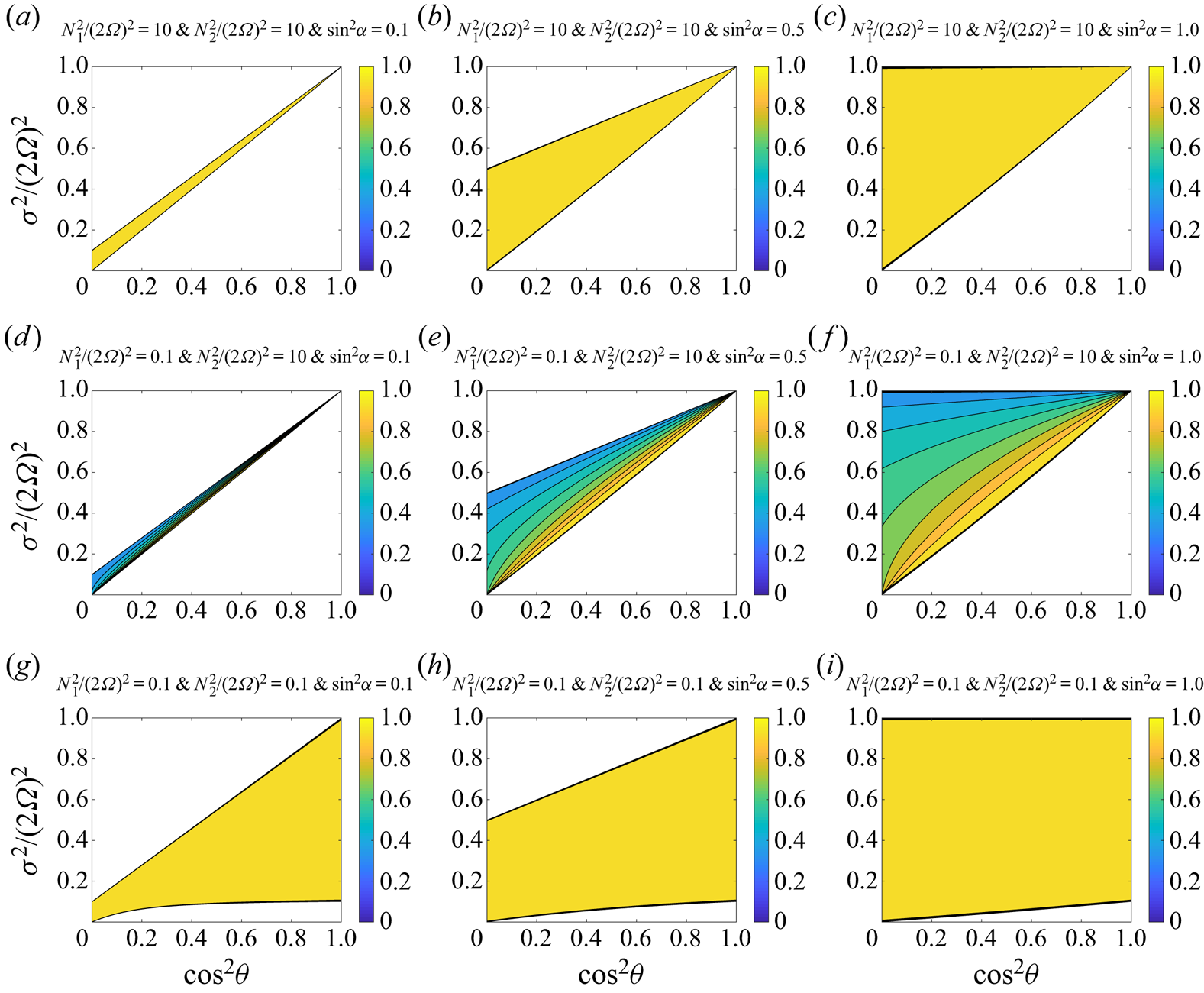
Figure 3 shows the transmission ratio  $\eta _{1}$ at three different combinations of
 $N_{1}^2$ and
 $N_{2}^2$. In figure 3(a–c), both stable layers are strongly stratified, but
 $N_{1}^2/(2\varOmega )^2$ is equal to
 $N_{2}^2/(2\varOmega )^2$. This clearly shows that the transmission is enhanced. Figure 3(d–f) shows the result of the cases with one weakly and one strongly stratified layer. Apparently, the transmission is not as efficient as the cases shown panels (a,b,c). Figure 3(g–i) presents the result of the cases with two weakly stratified stable layers. The transmission is efficient because the rotational effect is important. In a previous study on wave transmission in a two-layer structure (Cai et al. Reference Cai, Yu and Wei2021), it has been shown that a wave can be efficiently transmitted when the stable layer is weakly stratified. From figure 3, we also observe that
 $\sin ^2\alpha$ has important effect on the frequency range. Frequency range increases with increasing
 $\sin ^2\alpha$. When stable layers (or any of them) are strongly stratified, a wave can only survive in a very thin region if
 $\sin ^2\alpha$ is small. In the extreme case
 $\sin ^2\alpha =0$, the surviving frequency range vanishes.
Transmission coefficient  $\eta _{1}$ (the first part of (2.26)) for different
 $N_{1,2}^2/(2\varOmega )^2$ and
 $\sin ^2\alpha$ in a three-layer structure (one middle convective layer and two upper and lower neighbouring stable layers). The horizontal axis is
 $\cos ^2\theta$, and the vertical axis is
 $\sigma ^2/(2\varOmega )^2$. From the left to the right panels,
 $\sin ^2\alpha$ increases from 0.1 to 1.0. (a–c) Both stable layers are strongly stratified. (d–f) One stable layer is strongly stratified and the other is weakly stratified. (g–i) Both stable layers are weakly stratified. Wave propagation can only occur in coloured regions. Regions are left white if wave propagation is prohibited.

For the second part, the condition  $\cos ^2 (q_{1}{\rm \Delta} z'_{1})=0$ is equivalent to
 ${\rm \Delta} z'_{1}=(\ell +1/2) {\rm \pi}/|q_{1}|$, which requires that the thickness of the middle convective layer is a multiple-and-a-half of the half-wavelength of the propagating wave. In such a case, the overall transmission ratio is
 \begin{equation} \eta_{2}=\left[\frac{1}{4}\left(\sqrt{\frac{q_{1}^2}{s_{1}s_{2}}}+ \sqrt{\frac{s_{1}s_{2}}{q_{1}^2}}\right)^2\right]^{{-}1}. \end{equation}
Similarly,  $\eta _{2}$ only depends on the wavenumber ratio
 $s_{1}s_{2}/q_{1}^2$. It decreases with
 $s_{1}s_{2}/q_{1}^2$ when
 $s_{1}s_{2}/q_{1}^2>1$ and increases with
 $s_{1}s_{2}/q_{1}^2$ when
 $s_{1}s_{2}/q_{1}^2<1$. Let us consider two cases
 $C>0$ and
 $C<0$. For the first case we have
 $|s_{1,2}|<|q_{1}|$, while for the second case we have
 $|s_{1,2}|>|q_{1}|$. Thus, for
 $C>0$, we obtain
 $s_{1}s_{2}/q_{2}^2<1$ and
 $\eta _{2}$ always increases with
 $s_{1}s_{2}/q_{1}^2$. While for the other case,
 $C<0$, we obtain
 $s_{1}s_{2}/q_{2}^2>1$ and
 $\eta _{2}$ always decreases with
 $s_{1}s_{2}/q_{1}^2$. Efficient transmission can occur if
 $s_{1}s_{2}/q_{1}^2 \rightarrow 1$, which basically requires both
 $N_{1}^2C/(B^2-A_{0}C)$ and
 $N_{2}^2C/(B^2-A_{0}C)$ to be small. This indicates that the transmission ratio will decrease if both
 $N_{1}^2/(2\varOmega )^2$ and
 $N_{2}^2/(2\varOmega )^2$ increase, no matter what the sign of
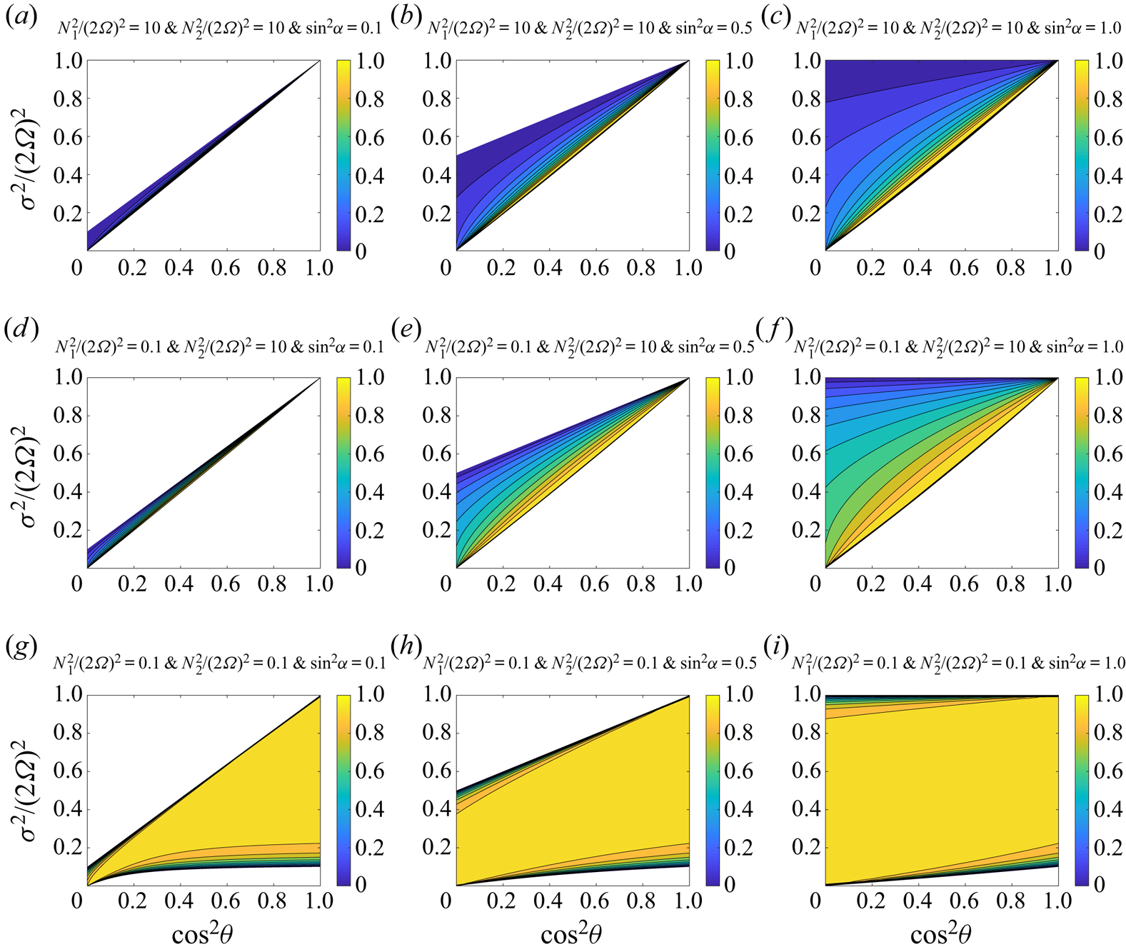
 $C$ is. Figure 4 gives an example of such case. Apparently, it can be seen that the transmission ratio decreases when the stable layers are varied from weakly stratified (g,h,i) to strongly stratified (a,b,c). Also apparent is that transmission is efficient near the critical colatitudes, where
 $N_{1,2}^2C/(B^2-A_{0}C) \rightarrow 0$.
Transmission coefficient  $\eta _{2}$ (the second part of (2.26)) for different
 $N_{1,2}^2/(2\varOmega )^2$ and
 $\sin ^2\alpha$ in a three-layer structure (one middle convective layer and two upper and lower neighbouring stable layers). The horizontal axis is
 $\cos ^2\theta$, and the vertical axis is
 $\sigma ^2/(2\varOmega )^2$. From the left to the right panels,
 $\sin ^2\alpha ^2$ increases from 0.1 to 1.0. (a–c) Both stable layers are strongly stratified. (d–f) One stable layer is strongly stratified and the other is weakly stratified. (g–i) Both stable layers are weakly stratified. Wave propagation can only occur in coloured regions. Regions are left white if wave propagation is prohibited.

Although the deduced transmission ratio (2.26) is for configuration 1, it can be generalized to other configurations. For configuration 2 (figure 2b), the stable layer is embedded between two convective layers. We label the stable layer as  $m+1/2$, and the neighbouring convective layers as
 $m$ and
 $m+1$. The neighbouring upper and lower interfaces of the stable layer
 $m+1/2$ are at
 $z_{m}$ and
 $z'_{m}$. In this setting, the transmission ratio can be deduced by simply interchanging
 $q_{m}$ with
 $s_{m}$ in (2.26). Therefore, we obtain the overall transmission ratio in configuration 2 as
 \begin{align} \eta= \left[\frac{1}{4}\left(\sqrt{\frac{q_{1}}{q_{2}}}+ \sqrt{\frac{q_{2}}{q_{1}}}\right)^2\cos^2 (s_{1}{\rm \Delta} z'_{1}) + \frac{1}{4}\left(\sqrt{\frac{s_{1}^2}{q_{1}q_{2}}}+ \sqrt{\frac{q_{1}q_{2}}{s_{1}^2}}\right)^2\sin^2(s_{1} {\rm \Delta} z'_{1})\right]^{{-}1}. \end{align}
The wavenumbers in the convective layers are all the same, thus we have
 \begin{equation} \eta=\left[\cos^2(s_{1}{\rm \Delta} z'_{1})+\frac{1}{4}\left(\left|\frac{s_{1}}{q_{1}}\right| +\left|\frac{q_{1}}{s_{1}}\right|\right)^2\sin^2(s_{1}{\rm \Delta} z'_{1})\right]^{{-}1}.\end{equation}
Again, we can show that wave transmission is enhanced when the thickness of the middle stable layer is a multiple of the half-wavelength of the propagating wave.
2.1.2. The multiple-layer case
Now we consider the structure with more alternating layers. Here, we first discuss the case of  $2M+1$ alternating layers (
 $M+1$ stable layers and
 $M$ convective layers), and both the lowermost and uppermost layers are stable. From the recursive relation (2.15), we have
 \begin{equation} \left[ \begin{array}{@{}c@{}} a_{1}\\ b_{1} \end{array} \right]=\prod_{m=1}^{M} \boldsymbol{\mathsf{T}}_{m,m+1} \left[ \begin{array}{@{}c@{}} a_{M+1}\\ b_{M+1} \end{array} \right]=\left[ \begin{array}{@{}cc@{}} {\mathsf{T}}_{11} & {\mathsf{T}}_{12}\\ {\mathsf{T}}_{21} & {\mathsf{T}}_{22} \end{array} \right] \left[ \begin{array}{@{}c@{}} a_{M+1} \\ b_{M+1} \end{array} \right].\end{equation}
Letting  $a_{M+1}=0$, we obtain that the wave amplitude of the transmitted wave in the uppermost layer is
 $b_{M+1}={\mathsf{T}}_{22}^{-1}b_{1}$, and the transmission ratio is
 \begin{equation} \eta=\left|\frac{s_{M+1}}{s_{1}}\right|\frac{1}{|{\mathsf{T}}_{22}|^2}. \end{equation}
Now we discuss the case of  $2M$ alternating layers (
 $M$ stable layers and
 $M$ convective layers), and the lowermost layer is stable and the uppermost layer is convective. Using the recursive relation (2.15) and combining it with the boundary conditions at the uppermost interface, we have
 \begin{equation} \left[ \begin{array}{@{}c@{}} a_{1}\\ b_{1} \end{array} \right]=\left(\prod_{m=1}^{M-1} \boldsymbol{\mathsf{T}}_{m,m+1}\right) S_{M}^{{-}1}\varLambda_{M,M}Q_{M,M} \left[ \begin{array}{@{}c@{}} c_{M}\\ d_{M} \end{array} \right]=\left[ \begin{array}{@{}cc@{}} {\mathsf{T}}'_{11} & {\mathsf{T}}'_{12}\\ {\mathsf{T}}'_{21} & {\mathsf{T}}'_{22} \end{array} \right] \left[ \begin{array}{@{}c@{}} c_{M}\\ d_{M} \end{array} \right],\end{equation}
where  ${\mathsf{T}}_{ij}',i,j\in \{1,2\}$ is defined by the matrix multiplications shown in the middle of (2.33). Letting
 $c_{M}=0$, we obtain that the wave amplitude of the transmitted wave in the uppermost layer is
 $d_{M+1}={\mathsf{T}}'_{22}b_{1}$, and the transmission ratio is
 \begin{equation} \eta=\left|\frac{q_{M}}{s_{1}}\right|\frac{1}{|{\mathsf{T}}'_{22}|^2}. \end{equation}
Again, following similar procedures, we can deduce the transmission ratio of configuration 2 by interchanging  $q_{m}$ with
 $s_{m}$.
We have shown that the transmission can be enhanced in the three-layer structure of configuration 1. Now we investigate whether the enhancement occurs in a structure with more layers. For the sake of simplicity, we assume that all convective layers have the same thickness  ${\rm \Delta} z_{c}$ and wavenumber
 $q$, and all stable layers have the same thickness
 ${\rm \Delta} z_{s}$ and wavenumber
 $s$.
We first discuss the case when the number of layers ( $2M+1$) is odd. When
 $s_{m}=s, q_{m}=q$ and
 ${\rm \Delta} z'_{m}={\rm \Delta} z_{c}$, the transfer matrix
 $\boldsymbol{\mathsf{T}}_{m,m+1}={\mathsf{T}}$ is
 \begin{gather} \hat{{\mathsf{T}}}_{11}=\frac{1}{4}\ \textrm{e}^{-\textrm{i}s{\rm \Delta} z_{c}} \left\{\left[2+\left(\frac{q}{s}+\frac{s}{q}\right)\right]\ \textrm{e}^{\textrm{i}q{\rm \Delta} z_{c}}+\left[2-\left(\frac{q}{s}+\frac{s}{q}\right)\right] \textrm{e}^{-\textrm{i}q{\rm \Delta} z_{c}}\right\}, \end{gather}
 \begin{gather}\hat{{\mathsf{T}}}_{12}=\frac{1}{4}\ \textrm{e}^{\textrm{i}(sz_{m}+s z'_{m})} \left[\left(\frac{q}{s}-\frac{s}{q}\right)\ \textrm{e}^{\textrm{i}q{\rm \Delta} z_{c}}- \left(\frac{q}{s}-\frac{s}{q}\right)\ \textrm{e}^{-\textrm{i}q{\rm \Delta} z_{c}}\right], \end{gather}
with  $\hat {{\mathsf{T}}}_{22}=\hat {{\mathsf{T}}}_{11}^{*}$ and
 $\hat {{\mathsf{T}}}_{21}=\hat {{\mathsf{T}}}_{12}^{*}$. The eigenvalue satisfies the following equation:
 \begin{equation} (\hat{{\mathsf{T}}}_{11}-\lambda)(\hat{{\mathsf{T}}}_{22}-\lambda)=\hat{{\mathsf{T}}}_{12}\hat{{\mathsf{T}}}_{21}. \end{equation}
After some manipulations, the equation can be written as
 \begin{equation} \lambda^2-2 {\rm Re}(\hat{{\mathsf{T}}}_{11})\lambda+1=0, \end{equation}
or in an explicit form
 \begin{equation} \lambda^2-2\left[\cos (q{\rm \Delta} z_{c})\cos (s{\rm \Delta} z_{c})+\frac{1}{2}\left(\frac{q}{s}+\frac{s}{q}\right)\sin(q{\rm \Delta} z_{c})\sin(s{\rm \Delta} z_{c})\right]\lambda+1=0, \end{equation}
where  ${\rm Re}$ denotes the real part of a complex number. Let
 $\lambda _{1,2}$ be the two roots of the equation. Obviously, we have
 $\lambda _{1}\lambda _{2}=1$. Let
 \begin{gather} \varDelta_{\lambda} =\left[\cos (q{\rm \Delta} z_{c})\cos (s{\rm \Delta} z_{c})+\frac{1}{2}\left(\frac{q}{s}+\frac{s}{q}\right) \sin(q{\rm \Delta} z_{c})\sin(s{\rm \Delta} z_{c})\right]^2-1 \end{gather}
 \begin{gather}=\left\{\cos [(q-s){\rm \Delta} z_{c}]+\frac{1}{2} \left(\frac{q}{s}+\frac{s}{q}-2\right) \sin(q{\rm \Delta} z_{c})\sin(s{\rm \Delta} z_{c})\right\}^2-1. \end{gather}
Then, the eigenvalues  $\lambda _{1,2}$ are real when
 $\varDelta _{\lambda }>0$, and are complex when
 $\varDelta _{\lambda }<0$. If
 $\lambda _{1,2}$ are real and
 $\lambda _{1}\neq \lambda _{2}$, then the maximum of
 $|\lambda _{1,2}|$ must be greater than one. For a multi-layer structure, the transfer matrix
 $\boldsymbol{\mathsf{T}}^{M} \propto {\rm max}(|\lambda _{1,2}|)^{M}$, which yields
 $\eta \propto {\rm max}(|\lambda _{1,2}|)^{-M}$. Since
 ${\rm max}(|\lambda _{1,2}|)$ is greater than one, the transmission ratio decays with the number of layers.
To ensure that the transmission does not decay, the solution  $\lambda _{1,2}$ must be on the unit circle of the complex plane. This condition can be achieved when
 $\lambda _{1}=\lambda _{2}=\pm 1$, or
 $\lambda _{1,2}$ are a complex pair. Therefore, a necessary condition (not sufficient) for efficient wave transmission is
 $\varDelta _{\lambda }\leq 0$.
It should be emphasized that the condition  $\varDelta _{\lambda }\leq 0$ is not a sufficient condition. The transmission ratio is actually determined by
 $|{\mathsf{T}}_{22}|$, which could possibly be much greater than one even though the eigenvalues
 $\lambda _{1,2}$ are on the unit circle. Here, we take a further step to discuss when the value
 $|{\mathsf{T}}_{22}|$ will be close to one, so as to ensure an efficient wave transmission.
Let us further define  $z=0$ at the lowest interface, and
 $\alpha _{1}=\exp (-\textrm {i}s{\rm \Delta} z_{s})$ and
 $\alpha _{2}=\exp (-\textrm {i}s{\rm \Delta} z_{c})$. With such definitions, we have
 $z_{m}+z_{m}'=(2m-2){\rm \Delta} z_{s}+(2m-1){\rm \Delta} z_{c}$ and
 $\exp [-{\rm i}s(z_{m}+z_{m}')]=\alpha _{1}^{2m-2}\alpha _{2}^{2m-1}$. The transfer matrix can be rewritten as
 \begin{equation}
\boldsymbol{\mathsf{T}}_{m,m+1}=\left[ \begin{array}{@{}cc@{}}
\alpha_{2}\tilde{{\mathsf{T}}}_{11} &
{\alpha_{1}^{*}}^{2m-2}{\alpha_{2}^{*}}^{2m-1}\tilde{{\mathsf{T}}}_{12}\\
{\alpha_{1}}^{2m-2}{\alpha_{2}}^{2m-1}\tilde{{\mathsf{T}}}_{12}^{*} &
\alpha_{2}^{*}\tilde{{\mathsf{T}}}_{11}^{*} \end{array}
\right], \end{equation}
where
 \begin{gather} \tilde{{\mathsf{T}}}_{11}=\frac{1}{4}\left\{\left[2+\left(\frac{q}{s}+ \frac{s}{q}\right)\right]\ \textrm{e}^{\textrm{i}q{\rm \Delta} z_{c}}+\left[2-\left(\frac{q}{s}+ \frac{s}{q}\right)\right]\ \textrm{e}^{-\textrm{i}q{\rm \Delta} z_{c}}\right\}, \end{gather}
 \begin{gather}\tilde{{\mathsf{T}}}_{12}=\frac{1}{4}\left[\left(\frac{q}{s}- \frac{s}{q}\right)\ \textrm{e}^{\textrm{i}q{\rm \Delta} z_{c}}-\left(\frac{q}{s}- \frac{s}{q}\right)\ \textrm{e}^{-\textrm{i}q{\rm \Delta} z_{c}}\right]. \end{gather}
When  $m=1$, we note that the transfer matrix
 $\boldsymbol{\mathsf{T}}_{1,2}$ can be formulated as
 \begin{equation}
\boldsymbol{\mathsf{T}}_{1,2}=\left[ \begin{array}{@{}cc@{}}
\alpha_{2}\tilde{{\mathsf{T}}}_{11} & {\alpha_{2}^{*}}\tilde{{\mathsf{T}}}_{12}\\
{\alpha_{2}}\tilde{{\mathsf{T}}}_{12}^{*} &
\alpha_{2}^{*}\tilde{{\mathsf{T}}}_{11}^{*} \end{array}
\right] =\boldsymbol{\mathsf{A}}\left[ \begin{array}{@{}cc@{}} \alpha_{2}
& 0\\ 0 & \alpha_{2}^{*} \end{array} \right],
\end{equation}
where
 \begin{equation} \boldsymbol{\mathsf{A}}=\left[ \begin{array}{@{}cc@{}} \tilde{{\mathsf{T}}}_{11} & \tilde{{\mathsf{T}}}_{12}\\ \tilde{{\mathsf{T}}}_{12}^{*} & \tilde{{\mathsf{T}}}_{11}^{*} \end{array} \right]. \end{equation}
Here, we consider a special case with  $\alpha _{1}^2={\alpha _{1}^{*}}^2=1$, which can be achieved by letting
 $|s|{\rm \Delta} z_{s}=\ell ' {\rm \pi}$, where
 $\ell '$ is a non-negative integer. For this special case, it can be proved that
 \begin{equation} \prod_{m=1}^{M} \boldsymbol{\mathsf{T}}_{m,m+1} =\boldsymbol{\mathsf{A}}^{M}\left[ \begin{array}{@{}cc@{}} {\alpha_{2}}^M & 0\\ 0 & {{\alpha_{2}}^{*}}^{M} \end{array} \right]. \end{equation}
Now we try to derive the explicit form of  $\boldsymbol{\mathsf{A}}^{M}$. It is obvious that
 $\tilde {{\mathsf{T}}}_{12}$ is a pure imaginary number, thus we can write
 $\boldsymbol{\mathsf{A}}$ as
 \begin{equation} \boldsymbol{\mathsf{A}}=\left[
\begin{array}{@{}cc@{}} {\rm Re}(\tilde{{\mathsf{T}}}_{11})+{\rm i}{\rm
Im}(\tilde{{\mathsf{T}}}_{11}) & {\rm i}{\rm
Im}(\tilde{{\mathsf{T}}}_{12})\\ -{\rm i}{\rm
Im}(\tilde{{\mathsf{T}}}_{12}) & {\rm Re}(\tilde{{\mathsf{T}}}_{11})-{\rm i}{\rm
Im}(\tilde{{\mathsf{T}}}_{11}) \end{array} \right]=\cos(q
{\rm \Delta} z_{c})\boldsymbol{\mathsf{I}}+{\rm i}\boldsymbol{\mathsf{U}},
\end{equation}
where
 \begin{equation} \boldsymbol{\mathsf{U}}= \left[
\begin{array}{@{}cc@{}} {\rm Im}(\tilde{{\mathsf{T}}}_{11}) & {\rm
Im}(\tilde{{\mathsf{T}}}_{12})\\ -{\rm
Im}(\tilde{{\mathsf{T}}}_{12}) & -{\rm Im}(\tilde{{\mathsf{T}}}_{11})
\end{array} \right], \end{equation}
and it is easy to verify
 \begin{equation} \boldsymbol{\mathsf{U}}^2=\sin^2(q{\rm \Delta} z_{c})\boldsymbol{\mathsf{I}}. \end{equation}
If  $\sin (q{\rm \Delta} z_{c})=0$, we can show
 $\boldsymbol{\mathsf{A}}=\cos (q{\rm \Delta} z_{c})\boldsymbol{\mathsf{I}}$ and
 $\boldsymbol{\mathsf{A}}^{M}=\cos ^{M}(q{\rm \Delta} z_{c})\boldsymbol{\mathsf{I}}$. If
 $\sin (q{\rm \Delta} z_{c})\neq 0$, then we obtain
 \begin{align} \boldsymbol{\mathsf{A}}^{M}&= (\cos(q {\rm \Delta} z_{c})\boldsymbol{\mathsf{I}}+{\rm i}\boldsymbol{\mathsf{U}})^{M}\end{align}
 \begin{align} &= \boldsymbol{\mathsf{I}}\sum_{k\in even}C_{k}^{M}\cos^{M-k}(q{\rm \Delta} z_{c}){\rm i}^{k}\sin^{k}(q{\rm \Delta} z_{c})\nonumber\\ &\quad +\boldsymbol{\mathsf{U}}[\sin(q{\rm \Delta} z_{c})]^{{-}1}\sum_{k\in odd}C_{k}^{M} \cos^{M-k}(q{\rm \Delta} z_{c}){\rm i}^{k}\sin^{k}(q{\rm \Delta} z_{c}) \end{align}
 \begin{align} &= \cos(Mq{\rm \Delta} z_{c})\boldsymbol{\mathsf{I}}+{\rm i}\sin(Mq{\rm \Delta} z_{c})[\sin(q{\rm \Delta} z_{c})]^{{-}1}\boldsymbol{\mathsf{U}}, \end{align}
where  $C_{k}^{M}=M!/((M-k)!k!)$ is the combination function. From the above calculation, the analytical solution of the transmission ratio can be obtained. If
 $\sin (q{\rm \Delta} z_{c})=0$, we have
 \begin{equation} {\mathsf{T}}_{22}={\alpha_{2}^{*}}^{M}\cos^{M}(q{\rm \Delta} z_{c}), \end{equation}
and the transmission ratio is
 \begin{equation} \eta=1. \end{equation}
If  $\sin (q{\rm \Delta} z_{c})\neq 0$, we have
 \begin{equation} {\mathsf{T}}_{22}={\alpha_{2}^{*}}^{M}\left[\cos(Mq{\rm \Delta} z_{c})- \textrm{i}\frac{1}{2}\left(\frac{q}{s}+\frac{s}{q}\right)\sin(Mq{\rm \Delta} z_{c})\right], \end{equation}
and the transmission ratio is
 \begin{equation} \eta=\left[\cos^2 (Mq{\rm \Delta} z_{c})+\frac{1}{4} \left(\frac{q}{s}+\frac{s}{q}\right)^2 \sin^2(Mq{\rm \Delta} z_{c})\right]^{{-}1}. \end{equation}
Equation (2.55) can be synthesized into (2.57), since  $\sin (q{\rm \Delta} z_{c})=0$ implies
 $\sin ^2(Mq{\rm \Delta} z_{c})=0$ and
 $\cos ^2(Mq{\rm \Delta} z_{c})=1$. Therefore, we conclude that, under the condition
 $|s|{\rm \Delta} z_{s}=\ell '{\rm \pi}$, the wave transmission ratio can be described by (2.57). Comparing with the result of three-layer structure case, we see that (2.26) is just a special case of (2.57) when
 $M=1$. The discussion on efficiency of wave transmission based on (2.57) is similar to that in three-layer structure case, and here we will not repeat it. From the analytical solution, it is clear that the wave will be totally transmitted when
 $M|q|{\rm \Delta} z_{c}=\ell {\rm \pi}$ and
 $|s|{\rm \Delta} z_{s}=\ell '{\rm \pi}$.
Analytical solution of the general cases of  $|s|{\rm \Delta} z_{s} \neq \ell '{\rm \pi}$ is more difficult, but some insights can be provided from the discussion of the eigenvalues of the transmission matrix. It is worth mentioning that, for the special case when
 $\sin q{\rm \Delta} z_{c}\rightarrow 0$ and
 $\sin s{\rm \Delta} z_{c}\rightarrow 0$, the eigenvalues
 $|\lambda _{1,2}|\rightarrow 1$. In this limit, it can be shown that
 \begin{equation} \varDelta_{\lambda}\sim \frac{[mod((q-s){\rm \Delta} z_{c},{\rm \pi})]^4}{12}>0, \end{equation}
where  $mod$ is the modulo function. The eigenvalues are real numbers, and one of
 $|\lambda _{1,2}|$ is slightly greater than 1. The transmission decays slowly as the wave crosses each layer. The wave transmission can be efficient when the number of layers is not too large. The eigenvalues can be estimated as
 \begin{equation} \lambda_{1,2}=\sqrt{1+\varDelta_{\lambda}}\pm \sqrt{\varDelta_{\lambda}}\sim 1\pm \frac{[mod((q-s){\rm \Delta} z_{c},{\rm \pi})]^2}{3\sqrt{2}}. \end{equation}
Thus, the decay rate of the transmission ratio is approximately  $\lambda _{2}^{-M} \sim \{1-12^{-1/2}M [mod((q-s){\rm \Delta} z_{c},{\rm \pi} )]^2\}^{-1}$. The transmission can be efficient when
 $M\ll M_{c}=[mod((q-s){\rm \Delta} z_{c},{\rm \pi} )]^{-2}$. When
 $mod((q-s){\rm \Delta} z_{c},{\rm \pi} )\rightarrow 0$, the critical value
 $M_{c}$ is very large. As a result, the transmission can be approximately efficient in this case. From the above discussion, we infer that the transmission can be efficient when
 $\sin (q{\rm \Delta} z_{c})\ll 1$ or
 $\sin (s{\rm \Delta} z_{c})\ll 1$. This conclusion is useful when embedded convective layers are very thin.
When the total number of layers is even ( $2M$), we can consider the case as one of
 $(2M-1)$ layers plus an additional layer. The best scenario for transmission for
 $(2M-1)$ layers is that the incident wave is totally transmitted to the
 $(2M-1)$th layer. Now the wave is incident from the
 $(2M-1)$th layer to the
 $(2M)$th layer, and it can be considered as a two-layer problem. For a two-layer problem, wave transmission is generally not efficient when the stable layer is strongly stratified (Wei Reference Wei2020a; Cai et al. Reference Cai, Yu and Wei2021).
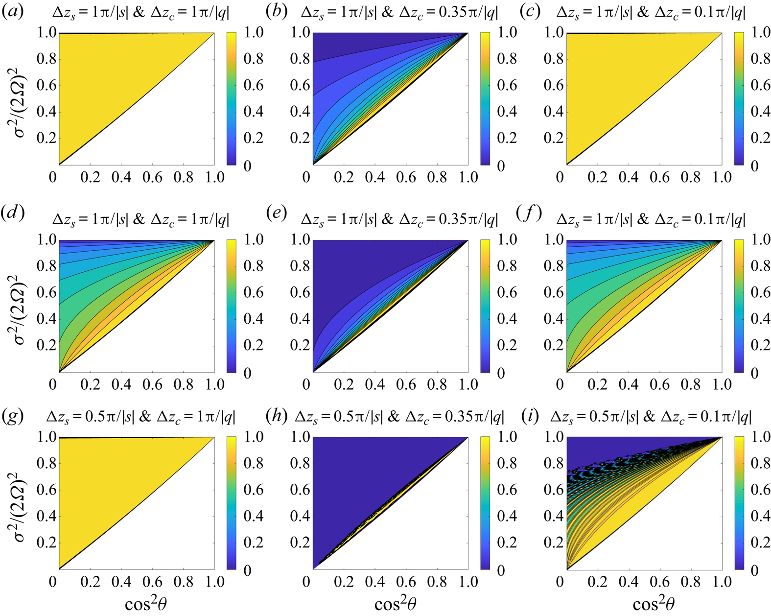
Figure 5 plots the transmission ratios in a 101-layer structure (a,b,c) and a 102-layer structure (d,e,f). In all the cases, we choose  $N_{m}^2/(2\varOmega )^2=10, \sin ^2\alpha =1$ and the lowermost layer is stable. Thus, in all cases, the stable layers are strongly stratified. This clearly shows that the transmission is enhanced in figure 5(a,c), where the total number of layers is odd and
 ${\rm \Delta} z_{c}$ and
 ${\rm \Delta} z_{s}$ satisfy the conditions
 $M|q|{\rm \Delta} z_{c}=\ell {\rm \pi}$ and
 $|s|{\rm \Delta} z_{s}=\ell '{\rm \pi}$. The transmission in figure 5(b) is not enhanced because
 $M|q|{\rm \Delta} z_{c} \neq \ell {\rm \pi}$. For the case of 102-layer structure (figure 5d,f), the transmission is not enhanced even when the above conditions are satisfied. For these two cases, the wave is almost totally transmitted from the first layer to 101st layer (see figure 5a,c). Wave transmission from the 101st layer to 102nd layer can be viewed as a two-layer problem, and it is generally not efficient when the stable layer is strongly stratified. Therefore, if the stable layer is strongly stratified, the enhancement of transmission only takes place when the number of alternating layers is odd. In other words, enhanced wave transmission only occurs in a multi-layer structure with stable layers embedded within convective layers, or convective layers embedded within stable layers. The enhancement of transmission also depends on the thicknesses of embedded layers
 ${\rm \Delta} z_{s}$. Figure 5(g–i) presents results of three cases with
 $|s|{\rm \Delta} z_{s}=0.5{\rm \pi}$ and different values of
 $|q|{\rm \Delta} z_{c}$. It can be seen that the transmission of the case
 $|q|{\rm \Delta} z_{c}={\rm \pi}$ is enhanced, while the transmission of the case
 $|q|{\rm \Delta} z_{c}=0.1{\rm \pi}$ is only partially enhanced.
Transmission ratios in multi-layer structures. For all the cases,  $N_{m}^2/(2\varOmega )^2=10$ and
 $\sin ^2\alpha =1$, and the lowermost layer is stable;
 ${\rm \Delta} z_{s}={\rm \pi} /|s|$ for (a–f) but
 ${\rm \Delta} z_{s}=0.5{\rm \pi} /|s|$ for (g–i). In each case, all the convective layers have the same thickness
 ${\rm \Delta} z_{c}$ and wavenumber
 $q$, and all the stable layers have the same thickness
 ${\rm \Delta} z_{s}$ and wavenumber
 $s$. (a–c) The transmission ratio for a 101-layer structure with
 ${\rm \Delta} z_{c}=(1,0.35,0.1){\rm \pi} /|q|$. (d–f) The transmission ratio for a 102-layer structure with
 ${\rm \Delta} z_{c}=(1,0.35,0.1){\rm \pi} /|q|$. (g–i) Similar to (a–c) but with different
 ${\rm \Delta} z_{s}$. Wave propagation can only occur in coloured regions. Regions are left white if wave propagation is prohibited.

The result obtained in the configuration 1 is also true in the configuration 2. Here, we do not repeat the discussion on configuration 2. André et al. (Reference André, Barker and Mathis2017) have also observed that wave transmission can be enhanced in a multi-layer structure. They provided a physical explanation for the enhancement in wave transmission when the incident wave is resonant with waves in adjacent layers with half-wavelengths equal to the layer depth. Our analysis verifies this phenomenon from a mathematical point of view.
2.2. Wave tunnelling
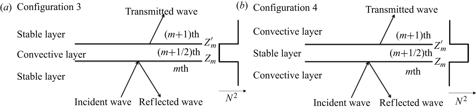
In the previous section, we have considered wave transmissions in multiple convective and radiative (stable) layers when the condition  $B^2-AC>0$ is satisfied everywhere in the domain. Here, we consider wave transmissions in two other configurations: (i) wave solution exists in stable layers but not in convective layers; (ii) wave solution exists in convective layers but not in stable layers. For the first configuration, a gravity wave can propagate in stable layers; and for the second configuration, an inertial wave can propagate in convective layers. Figure 6 shows the plots of a three-layer structure for the two configurations. In figure 6(a), the convective layer is embedded within two stable layers. In figure 6(b), the stable layer is embedded within two convective layers. For multiple layer structures in figure 6, although the wave cannot propagate in the whole domain, it still can transmit through a tunnelling process (Sutherland & Yewchuk Reference Sutherland and Yewchuk2004; Mihalas & Mihalas Reference Mihalas and Mihalas2013). In the following, we will discuss the tunnelling of gravity and inertial waves, respectively.
Two configurations of tunnelling of gravity and inertial waves. (a) Tunnelling of a gravity wave. Both top and bottom layers are stable. Gravity wave can propagate in the stable layer, but wave cannot propagate in the convective layer. (b) Tunnelling of an inertial wave. Both top and bottom layers are convective. Gravity wave can propagate in the convective layer, but wave cannot propagate in the stable layer.

2.2.1. Tunnelling of gravity waves
For configuration 3 in figure 6(a), the wave can propagate in the stable layer but cannot propagate in the convective layer. Thus the wave frequency must be in the range  $\sigma _{4}^2<\sigma ^2<\sigma _{5}^2$. The width of the frequency domain can be written as
 \begin{equation} \sigma_{5}^2-\sigma_{4}^2=\tfrac{1}{2}\left[(N_{min}^2 -f^2-\tilde{f}_{s}^2)+\sqrt{(N_{min}^2 -f^2-\tilde{f}_{s}^2)^2 +4N_{min}^2 \tilde{f}_{s}^2}\right]. \end{equation}
For the sake of convenience, we only discuss waves at the northern hemisphere ( $\theta \in [0,{\rm \pi} /2]$). The result at the southern hemisphere can be inferred from the symmetry property. From (2.60), it can be proved that
 $\sigma _{5}^2-\sigma _{4}^2$ always increases with
 $\theta , \sin ^2\alpha$, and
 $N_{min}^2/(2\varOmega )^2$ (see Appendix B). Therefore, the frequency domain is wider at the equatorial regions than at the polar regions. Also, it is wider when the meridional wavenumber dominates the zonal wavenumber, and it is wider when the degree of stratification is stronger.
Now we discuss the wave tunnelling in configuration 3. We use the same setting as that discussed in wave propagation. The derivation of wave transmission by tunnelling is similar to that of wave propagation. The only difference is that now the wave cannot propagate in the convective layer, and thus  $q_{m}={\rm i}\hat {q}_{m}$ is a pure imaginary number. Then the transfer relation from the
 $m$th layer to the
 $(m+1)$th layer can be easily obtained by replacing
 $q_{m}$ with
 ${\rm i}\hat {q}_{m}$ in (2.15).
Replacing  $q_{m}$ with
 ${\rm i}\hat {q}_{m}$ in (2.15), we can obtain the transfer matrix. In this configuration, we always have
 $C=f^2-\sigma ^2<0$ (since
 $\sigma _{4}^2>f^2$). Hence, for an outgoing transmitted wave, we have
 $b_{M+1}=0$ (modified phase velocity has an opposite sign to the group velocity). Again, let us first discuss the transmission ratio for a three-layer structure. In such a case, we have
 $a_{1}={\mathsf{T}}_{11}a_{2}$ and
 \begin{align} {\mathsf{T}}_{11}=\frac{1}{4}\ \textrm{e}^{-\textrm{i}(s_{1}z_{1}-s_{2}z'_{1})}\left[(1+ \frac{\textrm{i}\hat{q}_{1}}{s_{1}}+\frac{s_{2}}{s_{1}}+\frac{s_{2}}{\textrm{i} \hat{q}_{1}})\ \textrm{e}^{-\hat{q}_{1}{\rm \Delta} z'_{1}}+(1-\frac{\textrm{i}\hat{q}_{1}}{s_{1}}+\frac{s_{2}}{s_{1}}- \frac{s_{2}}{\textrm{i}\hat{q}_{1}})\ \textrm{e}^{\hat{q}_{1}{\rm \Delta} z'_{1}}\right]. \end{align}
Thus the wave transmission ratio is
 \begin{align} \eta &=\left|\frac{s_{2}}{s_{1}}\right|\frac{1}{|{\mathsf{T}}_{11}|^2}\end{align}
 \begin{align} & =16\left[\left(\sqrt{\frac{s_{1}}{s_{2}}}+\sqrt{\frac{s_{2}}{s_{1}}} \right)^2(\textrm{e}^{-\hat{q}_{1} {\rm \Delta} z'_{1}}+\textrm{e}^{\hat{q}_{1}{\rm \Delta} z'_{1}})^{2}\right.\nonumber\\ &\quad \left.+\left(\sqrt{\frac{\hat{q}_{1}^2}{s_{1}s_{2}}} -\sqrt{\frac{s_{1}s_{2}}{\hat{q}_{1}^2}}\right)^{2}(\textrm{e}^{-\hat{q}_{1}{\rm \Delta} z'_{1}}-\textrm{e}^{\hat{q}_{1}{\rm \Delta} z'_{1}})^{2}\right]^{{-}1}\end{align}
 \begin{align} &=16\left\{\left(\sqrt{\frac{s_{1}}{s_{2}}}+\sqrt{\frac{s_{2}}{s_{1}}} \right)^2(\textrm{e}^{-\hat{q}_{1} {\rm \Delta} z'_{1}}+\textrm{e}^{\hat{q}_{1}{\rm \Delta} z'_{1}})^{2} \vphantom{\left[\left(\sqrt{\frac{\hat{q}_{1}^2}{s_{1}s_{2}}} +\sqrt{\frac{s_{1}s_{2}}{\hat{q}_{1}^2}}\right)^{2}-4\right]}\right.\nonumber\\ &\quad \left.+ \left[\left(\sqrt{\frac{\hat{q}_{1}^2}{s_{1}s_{2}}} +\sqrt{\frac{s_{1}s_{2}}{\hat{q}_{1}^2}}\right)^{2}-4\right][(\textrm{e}^{-\hat{q}_{1} {\rm \Delta} z'_{1}}+\textrm{e}^{\hat{q}_{1}{\rm \Delta} z'_{1}})^{2}-4]\right\}^{{-}1}. \end{align}
Obviously,  $\eta$ depends on the values of
 $s_{1}/s_{2}, \hat {q}_{1}^2/(s_{1}s_{2})$ and
 $|\hat {q}_{1}|{\rm \Delta} z'_{1}$. It increases with
 $s_{1}/s_{2}$ when
 $s_{1}/s_{2}<1$, and decreases with
 $s_{1}/s_{2}$ when
 $s_{1}/s_{2}>1$. Similarly, we see that it increases with
 $\hat {q}_{1}^2/(s_{1}s_{2})$ when
 $\hat {q}_{1}^2/(s_{1}s_{2})<1$, and decreases with
 $\hat {q}_{1}^2/(s_{1}s_{2})$ when
 $\hat {q}_{1}^2/(s_{1}s_{2})>1$. It is also noted that it decreases with
 $|\hat {q}_{1}|{\rm \Delta} z'_{1}$. Thus, an efficient transmission ratio can be achieved when
 $s_{1}\rightarrow s_{2}, \hat {q}_{1}^2 \rightarrow s_{1}s_{2}$ and
 $|\widehat {q_{1}}|{\rm \Delta} z'_{1}\rightarrow 0$. The condition
 $\hat {q}_{1}^2 \rightarrow s_{1}s_{2}$ can be relaxed if
 $|\widehat {q_{1}}|{\rm \Delta} z'_{1}\rightarrow 0$. Therefore, efficient transmission requires that the wavenumbers (
 $s_{1}$ and
 $s_{2}$) in the stable layers are similar in magnitude, and the thickness of the convective layer (
 ${\rm \Delta} z'_{1}$) is much smaller than the e-folding decay distance (
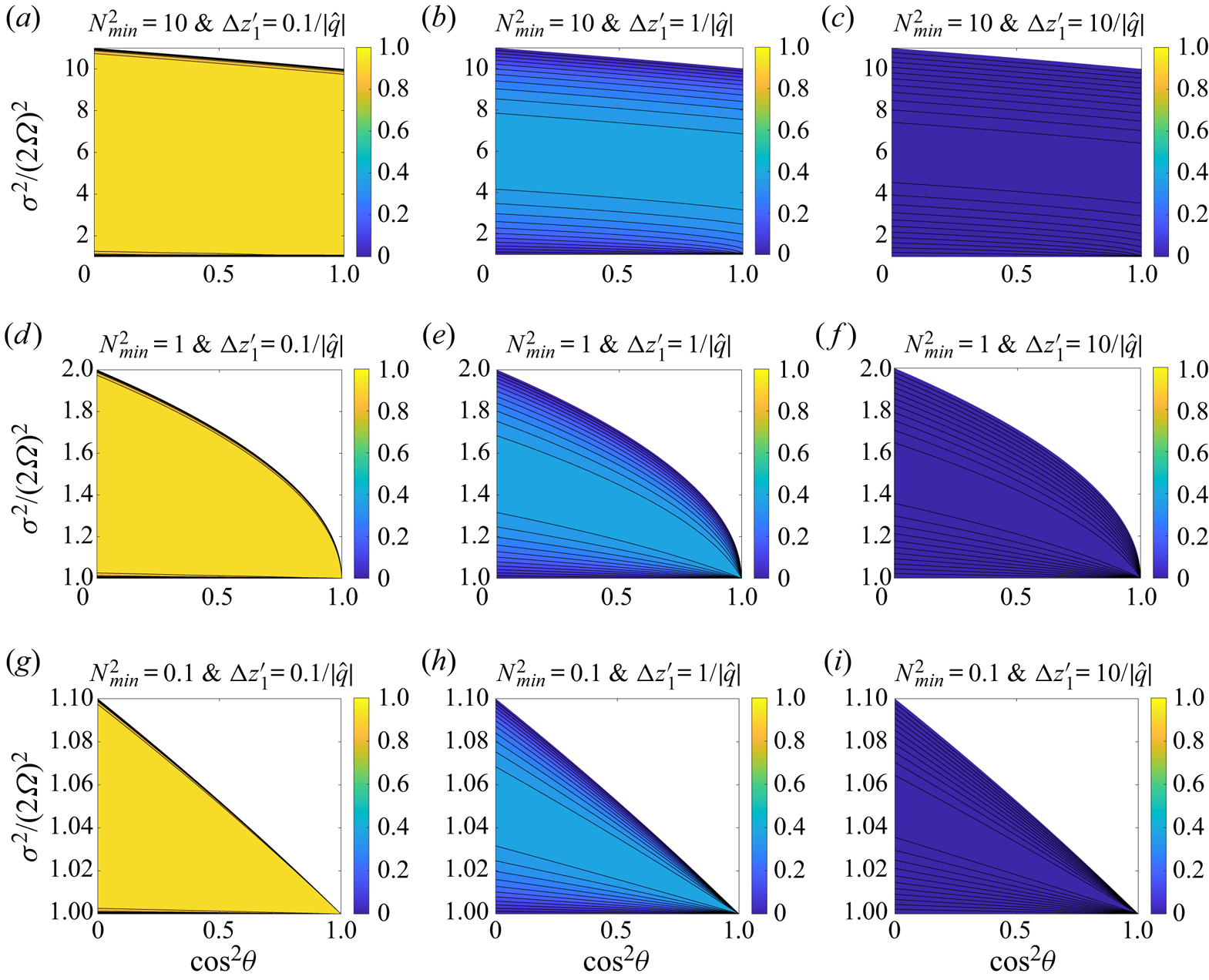
 $1/|\hat {q}_{1}|$). Figure 7 shows contour plots of the transmission ratios for different
 $N_{min}^2$ and
 ${\rm \Delta} z'_{1}$. In all cases, we set
 $s_{1}=s_{2}$ and
 $\sin ^2\alpha =1$. First, the figure clearly shows that the frequency domain increases with
 $N_{min}^2$ and
 $\theta$. This is consistent with the previous analysis on the width of the frequency domain. Second, we see that the transmission ratio is mainly affected by the thickness of the convective layer
 ${\rm \Delta} z'_{1}$. The shallower the convective layer is, the higher the transmission ratio is. We also note that the transmission ratio is insensitive to
 $N_{min}^2$. The effect of degree of stratification on the transmission ratio is insignificant.
Contour plots of transmission ratios for the tunnelling of a gravity wave in a three-layer structure. (a–c) Transmission ratios when the buoyancy frequency  $N_{min}^2=10$, and
 ${\rm \Delta} z'_{1}=(0.1,1,10)/|\hat {q}_{1}|$. (d–f) Transmission ratios when the buoyancy frequency
 $N_{min}^2=1$, and
 ${\rm \Delta} z'_{1}=(0.1,1,10)/|\hat {q}_{1}|$. (g–i) Transmission ratios when the buoyancy frequency
 $N_{min}^2=0.1$, and
 ${\rm \Delta} z'_{1}=(0.1,1,10)/|\hat {q}_{1}|$. tunnelling of gravity waves can only occur in coloured regions. Regions are left white if tunnelling of gravity waves is prohibited.

Now we consider the wave transmission in configuration 3 with more layers. Again, we assume that all of the stable layers have the same degree of stratification ( $N_{1}^2$) and thickness (
 ${\rm \Delta} z_{s}$). Similarly, we assume that all of the convective layers have the same thickness
 ${\rm \Delta} z_{c}$. With these conditions,
 $s_{m}=s$ and
 $q_{m}={\rm i}\hat {q}$ are constants in the stable and convective layers, respectively. When
 $s_{m}=s, q_{m}={\rm i}\hat {q}$ and
 ${\rm \Delta} z'_{m}={\rm \Delta} z_{c}$, the transfer matrix
 $\boldsymbol{\mathsf{T}}_{m,m+1}$ in (2.15) can be written as
 \begin{gather} \hat{{\mathsf{T}}}_{11}=\frac{1}{4}\ \textrm{e}^{-\textrm{i}s{\rm \Delta} z_{c}}\left\{\left[2+\textrm{i}\left(\frac{\hat{q}}{s}-\frac{s}{\hat{q}}\right)\right]\textrm{e}^{-\hat{q}{\rm \Delta} z_{c}}+\left[2-\textrm{i}\left(\frac{\hat{q}}{s}-\frac{s}{\hat{q}}\right)\right]\textrm{e}^{\hat{q}{\rm \Delta} z_{c}}\right\}, \end{gather}
 \begin{gather}\hat{{\mathsf{T}}}_{12}=\frac{1}{4}\ \textrm{e}^{\textrm{i}s(z_{m}+z_{m}')}\left\{\left[\left(\frac{\hat{q}}{s}+\frac{s}{\hat{q}}\right)\right]\textrm{e}^{-\hat{q}{\rm \Delta} z_{c}}-\left[\left(\frac{\hat{q}}{s}+\frac{s}{\hat{q}}\right)\right]\textrm{e}^{\hat{q}{\rm \Delta} z_{c}}\right\}, \end{gather}
with  $\hat {{\mathsf{T}}}_{22}^{*}=\hat {{\mathsf{T}}}_{11}$ and
 $\hat {{\mathsf{T}}}_{21}=\hat {{\mathsf{T}}}_{12}^{*}$. The eigenvalues of
 $\boldsymbol{\mathsf{T}}_{m,m+1}$ are the roots of the following equation:
 \begin{equation} \lambda^2-2{\rm Re}(\hat{{\mathsf{T}}}_{11})\lambda+1=0. \end{equation}
Similarly, we can obtain a sufficient condition for efficient wave tunnelling if
 \begin{equation} \varDelta_{\lambda}=\left[\frac{1}{2}(\textrm{e}^{-\hat{q}{\rm \Delta} z_{c}} +\textrm{e}^{\hat{q}{\rm \Delta} z_{c}})\cos(s{\rm \Delta} z_{c})+\frac{1}{4} \left(\frac{\hat{q}}{s}-\frac{s}{\hat{q}}\right)(\textrm{e}^{-\hat{q} {\rm \Delta} z_{c}}-\textrm{e}^{\hat{q}{\rm \Delta} z_{c}})\sin(s{\rm \Delta} z_{c})\right]^2-1, \end{equation}
and  $\varDelta _{\lambda }\leq 0$. It should be noted that
 $\varDelta _{\lambda }\leq 0$ is only a necessary but not sufficient condition for efficient transmission. If
 $|\hat {q}|{\rm \Delta} z_{c} \gg 0$, then
 $\varDelta _{\lambda }$ is likely to be greater than zero. Therefore, the probability is higher at small
 $|\hat {q}|{\rm \Delta} z_{c}$ for efficient transmission to take place.
By using similar technique as mentioned in § 2.1.2, we can find an analytical solution for the transmission ratio for the special case  $|s|{\rm \Delta} z_{s}=(\ell '+1/2) {\rm \pi}$ (so that
 $|s|{\rm \Delta} z_{s}-{\rm \pi} /2=\ell '{\rm \pi}$ and
 $\hat {{\mathsf{T}}}_{12}/\exp ({\rm \pi} /2)$ is a pure imaginary number, and the problem is analogous to that in § 2.1.2). Here, we only give the result without showing the details. Under the condition
 $|s|{\rm \Delta} z_{s}=(\ell '+1/2) {\rm \pi}$, the transmission ratio in the multi-layer structure for tunnelling of a gravity wave is
 \begin{align} \eta&=\left\{\cos^2 M\beta+\frac{1}{4}\left[\left(\frac{\hat{q}}{s}- \frac{s}{\hat{q}}\right)(\textrm{e}^{-\hat{q}{\rm \Delta} z_{c}} +\textrm{e}^{\hat{q}{\rm \Delta} z_{c}})\right]^2 \left[\left(\frac{\hat{q}}{s}+\frac{s}{\hat{q}}\right)^2 \right.\right.\nonumber\\ & \quad \left.\left. \vphantom{\left(\frac{\hat{q}}{s}+\frac{s}{\hat{q}}\right)} -(\textrm{e}^{-\hat{q}{\rm \Delta} z_{c}}+\textrm{e}^{\hat{q}{\rm \Delta} z_{c}})^2 \right]^{{-}1}\sin^2 M\beta\right\}^{{-}1}, \end{align}
where
 \begin{equation} \beta=\arg\left((\textrm{e}^{-\hat{q}{\rm \Delta} z_{c}}+\textrm{e}^{\hat{q} {\rm \Delta} z_{c}})+\textrm{i}\left[\left(\frac{\hat{q}}{s}+\frac{s}{\hat{q}}\right)^2 - (\textrm{e}^{-\hat{q}{\rm \Delta} z_{c}}+\textrm{e}^{\hat{q}{\rm \Delta} z_{c}})^2\right]^{1/2}\right), \end{equation}
and  $\arg$ is the argument function operating on complex numbers. Note that
 $\sin ^2 M\beta \propto ({\hat {q}}/{s}+{s}/{\hat {q}})^2 - (\textrm {e}^{-\hat {q}{\rm \Delta} z_{c}}+\textrm {e}^{\hat {q}{\rm \Delta} z_{c}})^2$, and there is no singularity problem in (2.69). From (2.69), we see that efficient tunnelling of gravity waves generally requires
 $|\hat {q}|{\rm \Delta} z_{c}$ to be small. In the limit
 $|\hat {q}|{\rm \Delta} z_{c}\rightarrow 0$, we find
 $\eta \rightarrow 1$. Thus, enhanced transmission of wave tunnelling can occur at
 $|\hat {q}|{\rm \Delta} z_{c}\rightarrow 0$ and
 $|s|{\rm \Delta} z_{s}=(\ell '+1/2) {\rm \pi}$. We call this phenomenon ‘resonant tunnelling’.
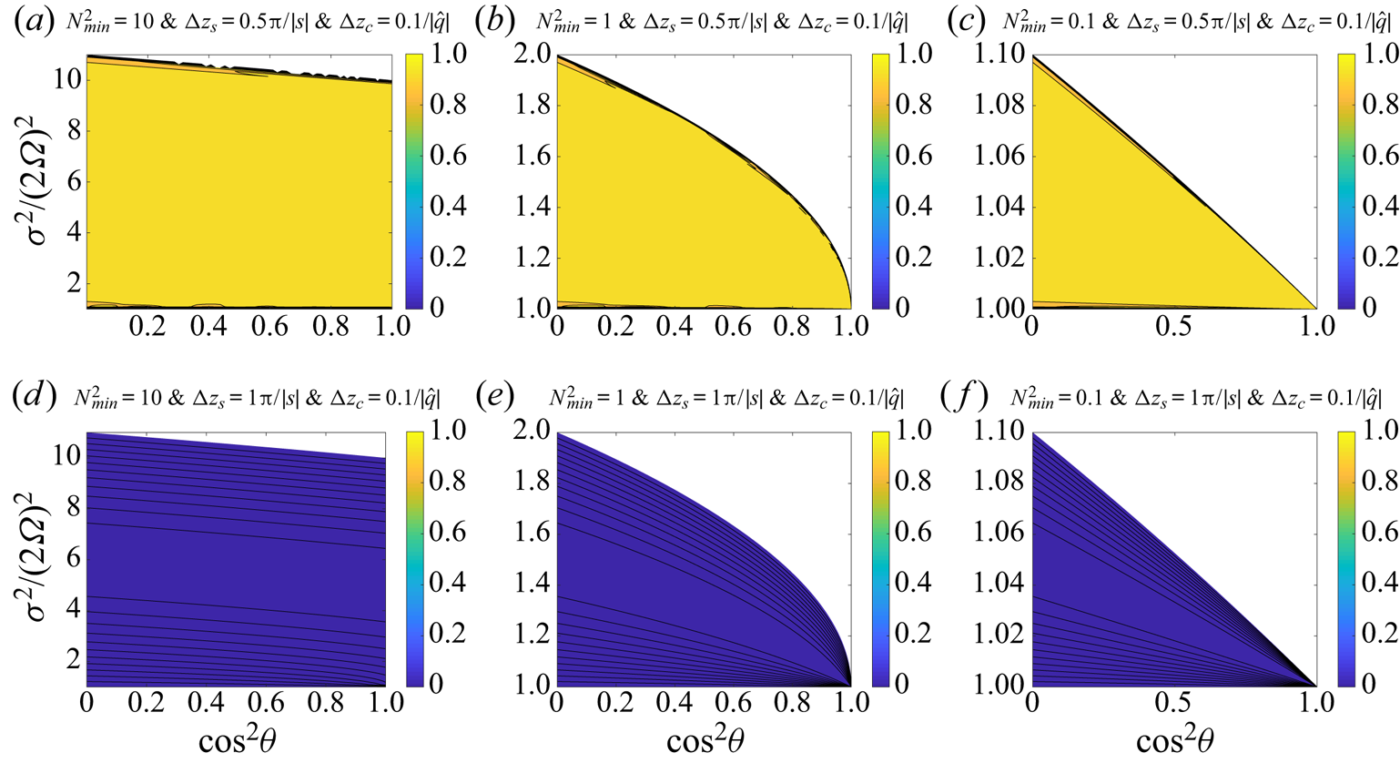
Figure 8 shows contour plots of the transmission ratios for different  $N_{min}^2$ in a 101-layer structure (
 $M=50$). In this calculation, all of the stable layers are assumed to have the same degree of stratification (
 $N_{min}^2$) and thickness (
 ${\rm \Delta} z_{s}$), and the convective layers are assumed to have the same thickness (
 ${\rm \Delta} z_{c}$). The analysis of the three-layer structure shows that efficient transmission only occurs when
 ${\rm \Delta} z_{c}$ is small. The mathematical analysis on the eigenvalues of the transfer matrices also indicates that efficient transmission is more likely to take place when
 ${\rm \Delta} z_{c}$ is small. For this reason, we set
 ${\rm \Delta} z_{c}=0.1/|\hat {q}|$ for all the computed cases. From the figure, we see that the transmission ratio is insensitive to the degree of stratification. Instead, the thickness of
 ${\rm \Delta} z_{s}$ is more important. In our calculations, we find that the transmission is efficient when
 ${\rm \Delta} z_{s}=(\ell +0.5) {\rm \pi}/|s|$, and inefficient when
 $z_{s}=\ell {\rm \pi}/|s|$, where
 $\ell$ is an integer. Therefore, the tunnelling of a gravity wave is efficient when each convective layer
 ${\rm \Delta} z_{c}$ is much shallower than the e-folding decay distance
 $1/|\hat {q}|$ and the thickness of each stable layer is close to a multiple-and-a-half of the half-wavelength.
Contour plots of transmission ratios for the tunnelling of a gravity wave in a multi-layer structure. The buoyancy frequency and thicknesses of the convective layers are all the same with the values of  $N_{min}^2$ and
 ${\rm \Delta} z_{c}$, and the thicknesses of the stable layers are all the same with the value of
 ${\rm \Delta} z_{s}$. (a–c) Transmission ratios when the buoyancy frequency
 $N_{min}^2=10,1,0.1, {\rm \Delta} z_{c}=0.1/|\hat {q}|$, and
 ${\rm \Delta} z_{s}=0.5{\rm \pi} /|\hat {s}|$. (d–f) Transmission ratios when the buoyancy frequency
 $N_{min}^2=10,1,0.1, {\rm \Delta} z_{c}=0.1/|\hat {q}|$, and
 ${\rm \Delta} z_{s}={\rm \pi} /|\hat {s}|$. Tunnelling of gravity waves can only occur in coloured regions. Regions are left white if tunnelling of gravity waves is prohibited.

2.2.2. Tunnelling of inertial waves
In this section, we discuss the tunnelling of inertial waves. Similarly, we consider a  $(2M+1)$-layer structure with alternating
 $M+1$ convective layers and
 $M$ stable layers. The plot is shown for configuration 4 in figure 6(b). For this configuration, an inertial wave can propagate in convective layers but no wave could propagate in stable layers, and thus the frequency range is
 $\sigma _{1}^2<\sigma ^2<\sigma _{2}^2$. The width of the frequency domain is
 \begin{equation} \sigma_{2}^2-\sigma_{1}^2=\tfrac{1}{2}\left[(f^2+\tilde{f}_{s}^2+N_{min}^2)- \sqrt{(f^2+\tilde{f}_{s}^2+N_{min}^2)^2-4N_{min}^2 f^2}\right]. \end{equation}
Analysis shows that  $\sigma _{2}^2-\sigma _{1}^2$ decreases with
 $\theta$ and
 $\sin ^2\alpha$, and increases with
 $N_{min}^2/(2\varOmega )^2$ (see Appendix C). Therefore, the frequency domain is wider at polar regions than equatorial regions. Also it is wider when the zonal wavenumber dominates the meridional wavenumber, and it is wider when the degree of stratification is stronger.
Now, we discuss the wave transmission of the tunnelling of an inertial wave. Again, we first consider a three-layer structure. It is not difficult to obtain the transmission ratio
 \begin{align} \eta=16\left\{4(\textrm{e}^{-\hat{s}_{1}{\rm \Delta} z'_{1}}+\textrm{e}^{\hat{s}_{1} {\rm \Delta} z'_{1}})^{2}+\left[\left(\sqrt{\frac{\hat{s}_{1}^2}{q_{1}^2}} +\sqrt{\frac{q_{1}^2}{\hat{s}_{1}^2}}\right)^{2}-4\right] \left[(\textrm{e}^{-\hat{s}_{1}{\rm \Delta} z'_{1}}+\textrm{e}^{\hat{s}_{1}{\rm \Delta} z'_{1}})^{2}-4\right]\right\}^{{-}1}. \end{align}
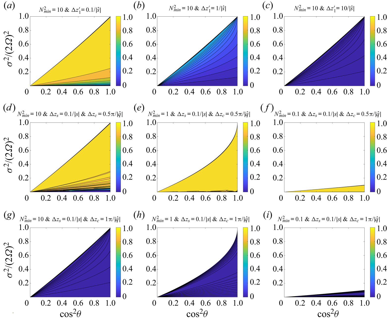
Again, we can show that efficient transmission requires that the thickness of the stable layer is much smaller than the e-folding decay distance  $1/|\hat {s}_{1}|$. Figure 9(a–c) shows the transmission ratios in the three-layer structure when the stable layer is strongly stratified. It clearly shows that the transmission is only efficient when
 $\hat {s}_{1}{\rm \Delta} z'_{1}$ is small.
Contour plots of transmission ratios for the tunnelling of an inertial wave: (a,b,c) are for the three-layer structure; and (d–i) are for the multi-layer structures. (a–c) Transmission ratios for  $N_{min}^2=10$ and
 ${\rm \Delta} z'_{1}=(0.1,1,10)/|\hat {s}|$ in a three-layer structure. (d–f) Transmission ratios for
 $N_{min}^2=(10,1,0.1), {\rm \Delta} z_{c}=0.5{\rm \pi} /|\hat {q}|$ and
 ${\rm \Delta} z_{s}=0.1/|s|$ in a 101-layer structure. (g–i) Transmission ratios for
 $N_{min}^2=(10,1,0.1), {\rm \Delta} z_{c}={\rm \pi} /|\hat {q}|$ and
 ${\rm \Delta} z_{s}=0.1/|s|$ in a 101-layer structure. Tunnelling of inertial waves can only occur in coloured regions. Regions are left white if Tunnelling of gravity waves is prohibited.

Now we discuss the tunnelling of an inertial wave in a structure with more layers. Similarly, we can use the recursive relations to calculate the transmission ratio. Here, we only give the result without showing details. Under the condition  $|q|{\rm \Delta} z_{c}=(\ell '+1/2){\rm \pi}$, we find the transmission ratio of the tunnelling of inertial waves in a multi-layer structure is
 \begin{align} \eta&=\left\{\cos^2 M\beta+\frac{1}{4}\left[\left(\frac{\hat{s}}{q}- \frac{q}{\hat{s}}\right)(\textrm{e}^{-\hat{s}{\rm \Delta} z_{s}}+\textrm{e}^{\hat{s} {\rm \Delta} z_{s}})\right]^2 \left[\left(\frac{\hat{s}}{q}+ \frac{q}{\hat{s}}\right)^2 \right.\right.\nonumber\\ &\left.\left.\quad - \vphantom{\left[\left(\frac{\hat{s}}{q}\right)\right]} (\textrm{e}^{-\hat{s}{\rm \Delta} z_{s}} +\textrm{e}^{\hat{s}{\rm \Delta} z_{s}})^2\right]^{{-}1}\sin^2 M\beta\right\}^{{-}1}, \end{align}
where
 \begin{equation} \beta=\arg\left((\textrm{e}^{-\hat{s}{\rm \Delta} z_{s}}+\textrm{e}^{\hat{s}{\rm \Delta} z_{s}})+\textrm{i}\left[\left(\frac{\hat{s}}{q}+\frac{q}{\hat{s}}\right)^2 - (\textrm{e}^{-\hat{s}{\rm \Delta} z_{s}}+\textrm{e}^{\hat{s}{\rm \Delta} z_{s}})^2\right]^{1/2}\right). \end{equation}
Figure 9(d–i) shows the transmission ratios in a 101-layer structure. Again, we see that the efficiency of transmission mainly depends on the thicknesses of the convective and stable layers. For the transmission to be efficient, it requires that the thickness of stable layer ( ${\rm \Delta} z_{s}$) is much smaller than the e-folding decay distance
 $1/|\hat {s}|$, and the thickness of each convective layer is close to a multiple-and-a-half of the half-wavelength. This result is similar to that obtained in the tunnelling of gravity waves.
3. Non-traditional effects
Sutherland (Reference Sutherland2016) has discussed wave transmission in a multi-layer structure in traditional approximation. It is necessary to investigate the non-traditional effects on wave transmission in the multi-layer structure. Under the traditional approximation ( $f_{s}^2=0$), the critical frequencies can be written as
 \begin{gather} \sigma_{1}^2=0, \quad \sigma_{4}^2=f^2, \end{gather}
 \begin{gather}\sigma_{2}^2={\rm min}(f^2,N_{min}^2), \quad \sigma_{5}^2={\rm max}(f^2,N_{min}^2), \end{gather}
 \begin{gather}\sigma_{3}^2={\rm min}(f^2,N_{max}^2), \quad \sigma_{6}^2={\rm max}(f^2,N_{max}^2). \end{gather}
If stable layers are strongly stratified with  $f^2 < N_{min}^2$, then
 $\sigma _{2}^2=\sigma _{3}^2=\sigma _{4}^2=f^2, \sigma _{5}^2=N_{min}^2$ and
 $\sigma _{6}^2=N_{max}^2$. In such a case, a wave cannot propagate in both convective and stable layers, while tunnelling of gravity waves occurs at
 $f^2 < \sigma ^2 < N_{min}^2$ and tunnelling of inertial waves occurs at
 $0 < \sigma ^2 < f^2$ (see the upper panel of figure 10).
Plots of wave propagation in multiple convectively stable and unstable layers. Wave frequency ranges are shown above and below the middle arrow for convective and stable layers, respectively. Wave propagation occurs in the green region, tunnelling of inertial wave occurs in the blue region and tunnelling of gravity wave occurs in the purple region.

If stable layers are weakly stratified with  $f^2>N_{max}^2$, then
 $\sigma _{4}^2=\sigma _{5}^2=\sigma _{6}^2=f^2, \sigma _{2}^2=N_{min}^2$ and
 $\sigma _{3}^2=N_{max}^2$. In such a case, tunnelling of gravity waves cannot occur, while a wave can propagate in both convective and stable layers at
 $N_{max}^2 < \sigma ^2 < f^2$, and tunnelling of inertial waves occurs at
 $0 < \sigma ^2 < N_{min}^2$ (see the lower panel of figure 10).
If the traditional approximation is made, wave propagation only occurs in weakly stratified flow, tunnelling of gravity waves only occurs in strongly stratified flow and tunnelling of inertial waves can occur in both strongly and weakly stratified flows. When non-traditional effects are included, however, no similar restriction is obtained in wave propagation or tunnelling. The non-traditional effects on wave propagation can already be seen by comparing figure 3(a,d,g) with figure 3(b,c,e,f,h,i). In the traditional approximation,  $\tilde {f}_{s}$ is set to zero and this can be achieved by setting
 $\sin \alpha =0$. Figure 3(a,d,g) shows transmission ratios with small
 $\tilde {f}_{s}$, which are similar to situations with traditional approximation. If
 $\tilde {f}_{s}=0$, the coloured regions in figure 3(a,d) vanish because wave propagation is prohibited when
 $N_{max}^2\geq f^2$; and the coloured region in figure 3(c) will shrink into a triangle region below the diagonal line
 $\sigma ^2/(2\varOmega )^2=\cos ^2\theta$ (see figure 11a). For weakly stratified flow (
 $N_{max}^2 < f^2$), only sub-inertial waves (
 $\sigma ^2 < f^2$) can propagate with the traditional approximation. However, super-inertial waves (
 $\sigma ^2>f^2$) can propagate if non-traditional effects are taken into account.
Wave transmissions with the traditional approximation. (a) Transmission for wave propagation. The setting is identical to that of figure 3(g) except that  $\tilde {f}_{s}^2=0$ here. (b) Tunnelling of gravity waves. The setting is the same as that in figure 8(a) except that
 $\tilde {f}_{s}^2=0$ here. (c–e) Tunnelling of inertial waves. The settings are the same as those in figure 9(d–f) except that
 $\tilde {f}_{s}^2=0$ here. Coloured and white regions have similar meanings as those mentioned in previous contour plots.

With the traditional approximation, tunnelling of gravity waves can only occur when stable layers are strongly stratified ( $N_{min}^2>f^2$), and the wave frequency is smaller than buoyancy frequency (
 $\sigma ^2 < N_{min}^2$). When non-traditional effects are present, we see from figure 8 that tunnelling of gravity waves can occur when stable layers are weakly stratified. Also, tunnelling of gravity waves is possible for super-buoyancy-frequency waves.
For tunnelling of inertial waves, comparing figure 11(c–e) with figure 9(d–f), we see that frequency ranges are overestimated in the traditional approximation. This is especially true when stable layers are weakly stratified. From figures 11(c) and 9(d), we also see that the traditional approximation has a moderate effect on the transmission ratio in the small frequency range.
4. Summary
In this paper, we have investigated wave transmissions in rotating stars or planets with multiple radiative and convective zones. Two situations have been considered: wave propagation and wave tunnelling. For wave propagation, waves could propagate in both convective and stable layers. Previous studies on wave propagation in a two-layer structure with a step function of stratification (Wei Reference Wei2020a; Cai et al. Reference Cai, Yu and Wei2021) have shown that wave transmission is generally not efficient when the stable layer is strongly stratified (this is a typical behaviour despite the fact that transmission can be efficient under certain conditions, such as at the critical latitude). In this work, however, we find that the wave transmission can be enhanced in a multiple-layer structure even though the stable layers are strongly stratified. We call this phenomenon ‘enhanced wave transmission’. Enhanced wave transmission can only occur when the top and bottom layers are both convective layers or stable layers. We have the following major findings on wave propagation:
(i) In a three-layer structure, transmission can be enhanced when the top and bottom layers (clamping layers) have a similar buoyancy frequency, and the thickness of the middle layer is close to a multiple of the half-wavelength of the propagating wave inside this layer.
(ii) Enhancement of transmission can also take place in a multi-layer structure under similar conditions when clamping layers have similar properties, the thickness of each clamping layer is close to a multiple of the half-wavelength of the propagating wave and the total thickness of each embedded layer is close to a multiple of the half-wavelength of the propagating wave. Efficient transmission can take place even when stable layers are strongly stratified. We call this phenomenon ‘resonant propagation’.
For wave tunnelling, there are two cases: the tunnelling of a gravity wave, and the tunnelling of an inertial wave. In the first case, waves can propagate in stable layers but are evanescent in convective layers. In the second case, on the other hand, waves can propagate in convective layers but are evanescent in stable layers. We have the following major findings on wavetunnelling:
(i) The tunnelling of a gravity wave can be efficient when stable layers have similar buoyancy frequencies, the thickness of each embedded convective layer is much smaller than the corresponding e-folding decay distance and the thickness of each stable layer is close to a multiple-and-a-half of the half-wavelength. The latter condition is unnecessary if the structure is three layered. We call this ‘resonant tunnelling of gravity waves’.
(ii) The tunnelling of an inertial wave can be efficient when stable layers have similar buoyancy frequencies, the thickness of each stable layer is much smaller than the corresponding e-folding decay distance and each convective layer thickness is close to a multiple-and-a-half of the half-wavelength. The latter condition is unnecessary if the structure is three layered. We call this ‘resonant tunnelling of inertial waves’.
(iii) The efficiency of the tunnelling mainly depends on the layer thicknesses, the wavelengths and the e-folding decay distances.
It would be interesting to investigate the tunnelling of gravity waves in a non-rotating fluid. This is a special case with  $f=0$ and
 $\widetilde {f_{s}}=0$. In such a case, we can easily obtain that
 $\hat {q}_{m}^2=k^2$ and
 $s_{m}^2=(N_{m}^2/\sigma ^2-1)k^2$, where
 $\sigma ^2 < N_{m}^2$. Then the conclusion (i) can be directly applied to this special case.
Table 1 summarizes conditions for efficient transmissions of wave propagation and tunnelling when all stable layers have similar buoyancy frequencies. For tunnelling waves, clamping layers should have similar properties. Table 1 only lists the conditions in such structures. The first column of table 1 lists four types of wave transmission: propagation with convective layers embedded, propagation with stable layers embedded, tunnelling of gravity waves and tunnelling of inertial waves. The second column gives the frequency ranges. The third and fourth columns show the conditions for efficient transmission. From the table, we see that the conditions for efficient wave transmission are significantly different among tunnelling and propagative waves.
Summary on efficient wave transmissions in a multi-layer structure.

Note:  $\lambda _{c}$ is the wavelength or decay distance in the convective layer;
 $\lambda _{s}$ is the wavelength or decay distance in the stable layer;
 ${\rm \Delta} z_{c}$ and
 ${\rm \Delta} z_{s}$ are the thicknesses of the convective and stable layers, respectively;
 $M$ is the number of embedded layers;
 $\ell$ and
 $\ell '$ are non-negative integers. IW and GW denote inertial and gravity waves, respectively. CLs and SLs denote convective and stable layers, respectively. Here, we only consider the situation that all stable layers have similar buoyancy frequencies, and clamping layers have similar properties.
Our findings have interesting implications for gaseous planets. In a multi-layer structure, Belyaev et al. (Reference Belyaev, Quataert and Fuller2015) found that the g-mode with vertical wavelengths smaller than the layer thickness are evanescent in gaseous planets. This is true for tunnelling of g-mode waves. However, if considering wave propagation, g-mode waves can transmit efficiently even when the wavelength is smaller than the layer thickness. André et al. (Reference André, Barker and Mathis2017) have made promising progress in the study of wave transmission in multi-layer structures, which reveals that wave transmission can be enhanced when the incident wave is resonant with waves in adjacent layers with half-wavelengths equal to the layer depth. Their result is consistent with our derivations. By deriving a group of exact solutions for wave transmission coefficients in multi-layer structures, we provide a mathematical explanation for why the transmission can be enhanced in a multi-layer structure. In addition, our analysis shows that wave transmission can also be enhanced in tunnelling of gravity waves or inertial waves. Conditions on ‘resonant propagation’ and ‘resonant tunnelling’ have been provided. Pontin et al. (Reference Pontin, Barker, Hollerbach, André and Mathis2020) have conducted interesting research on wave propagation in a multi-layer structure in a non-rotating sphere, and found that wave transmissions are efficient for very large wavelength waves. This already shares some similarities with our analysis on the tunnelling of gravity waves in the f-plane. It has to be emphasized that our model is derived under the assumptions in the local f-plane. Application of the results to a global sphere should be performed with caution for the following reasons. First, only short wavelengths are considered in the local model. Wave transmissions of global scale waves have not been discussed. Second, the geometrical effect has not been taken into account. This is important for waves propagating in a global sphere. For example, super-inertial waves propagating from the equator to the poles may change to sub-inertial waves across critical colatitudes, where waves can also be transmitted or reflected in the meridional direction (Rieutord & Valdettaro Reference Rieutord and Valdettaro1997; Rieutord, Georgeot & Valdettaro Reference Rieutord, Georgeot and Valdettaro2001; Gerkema & Shrira Reference Gerkema and Shrira2005a; Shrira & Townsend Reference Shrira and Townsend2010). Extending our work to a full spherical geometry will be a direction of improvement in the future.
Our findings may also have implications for the Earth's oceans, and in stars. It has been observed that there exists a multi-layer structure in theArctic Ocean, with thin stratified layers separated by mixed layers created by double diffusion (Rainville & Winsor Reference Rainville and Winsor2008). By performing a joint theoretical and experimental study, Ghaemsaidi et al. (Reference Ghaemsaidi, Dosser, Rainville and Peacock2016) revealed that the Arctic Ocean has a rich transmission behaviour. With their data, we can have a simple estimation on wave transmission in the Arctic Ocean by using our model. For the structure of the Arctic Ocean presented in Ghaemsaidi et al. (Reference Ghaemsaidi, Dosser, Rainville and Peacock2016),  $N$ in stratified layers is approximately
 $1.6\times 10^{-3}-3.2\times 10^{-3}\ \textrm {s}^{-1}$; the inertial frequency
 $f$ is approximately
 $1.4 \times 10^{-4}\ \textrm {s}^{-1}$; the thicknesses of embedded convective layers are of
 $O(1)$; the total depth of the multi-layer structure is approximately
 $30\ \textrm {m}$, which is approximately separated into 14 stable layers. Since
 $N\gg f$, gravity waves are expected to transport across the multi-layer structure by tunnelling. From table 1, we see that waves with wavelength
 $\lambda _{s}\sim 8.6\ \textrm {m}$ can be transmitted efficiently by resonant tunnelling. Near-inertial waves with wavelengths
 $10\text{--}50$ m can also transmit efficiently. This has been verified in Ghaemsaidi et al. (Reference Ghaemsaidi, Dosser, Rainville and Peacock2016). Double diffusion also occurs in stars. Our model may also provide some insights into wave transmission in stars. The interior structures are different for different types of stars. For example, as studied in Cai (Reference Cai2014), late-type stars have a convectively stable–unstable–stable three-layer structure; A–F type stars generally have complicated internal structures with two separated convectively unstable layers (for example, some of them have a unstable–stable–unstable three-layer structure, and some of them have a stable–unstable–stable–unstable–stable five-layer structure), and massive stars have a unstable–stable two-layer structure. For waves excited at the innermost layer, resonant wave propagation from the innermost to the outermost layers can probably take place in late-type and A–F stars since the top and bottom layers are both convectively stable or unstable. However, if waves are excited in the second innermost layer, enhanced wave transmission is unlikely to occur from this layer to the outermost layer, because the bottom and top layers of the interested region are different. For massive stars, enhanced wave transmission is unlikely to take place because the properties of the top and bottom layers are different. We have to mention that the stratified structure specified in our model is ideal. In our Boussinesq model, density variation and viscous effects have been ignored. In real stars, however, density variation and viscous effects may be important. In addition, our model assumes that the buoyancy frequency changes abruptly across interfaces between convective and stable layers. For real stars, the change is likely to be smoother. Previous investigations of wave transmission in two-layer structures with smoothly varying buoyancy frequencies have shown significant differences. Models with more realistic settings are desirable in the future.
Acknowledgements
We thank the four anonymous reviewers for providing helpful comments and suggestions on this manuscript.
Funding
T.C. has been supported by NSFC (No.11503097), the Guangdong Basic and Applied Basic Research Foundation (No.2019A1515011625), the Science and Technology Program of Guangzhou (No.201707010006), the Science and Technology Development Fund, Macau SAR (Nos.0045/2018/AFJ, 0156/2019/A3) and the China Space Agency Project (No.D020303). C.Y. has been supported by the National Natural Science Foundation of China (grants 11373064, 11521303, 11733010, 11873103), Yun-nan National Science Foundation (grant 2014HB048) and Yunnan Province (2017HC018). X.W. has been supported by National Natural Science Foundation of China (grant no.11872246) and Beijing Natural Science Foundation (grant no. 1202015). This work is partially supported by Open Projects Funding of the State Key Laboratory of Lunar and Planetary Sciences.
Declaration of interest
The authors report no conflict of interest.
Appendix A
Equations (2.11)–(2.14) can be written in a matrix form
 \begin{align} &\boldsymbol{\mathsf{S}}_{m}\left[ \begin{array}{@{}c@{}} a_{m}\\ b_{m} \end{array} \right]=\boldsymbol{\varLambda}_{m} \boldsymbol{\mathsf{Q}}_{m}\left[ \begin{array}{@{}c@{}} c_{m}\\ d_{m} \end{array} \right], \end{align}
 \begin{align} &\tilde{\boldsymbol{\varLambda}}_{m} \tilde{\boldsymbol{\mathsf{Q}}}_{m}\left[ \begin{array}{@{}c@{}} c_{m}\\ d_{m} \end{array} \right]= \tilde{\boldsymbol{\mathsf{S}}}_{m}\left[ \begin{array}{@{}c@{}} a_{m+1}\\ b_{m+1} \end{array} \right], \end{align}
where
 \begin{align} \boldsymbol{\mathsf{S}}_{m} &= \left[ \begin{array}{@{}cc@{}} \textrm{e}^{-\textrm{i}s_{m}z_{m}} & \textrm{e}^{\textrm{i}s_{m}z_{m}} \\ -\textrm{e}^{-\textrm{i}s_{m}z_{m}} & \textrm{e}^{\textrm{i}s_{m}z_{m}} \end{array} \right], \quad \boldsymbol{\mathsf{Q}}_{m} = \left[ \begin{array}{@{}cc@{}} \textrm{e}^{-\textrm{i}q_{m}z_{m}} & \textrm{e}^{\textrm{i}q_{m}z_{m}} \\ -\textrm{e}^{-\textrm{i}q_{m}z_{m}} & \textrm{e}^{\textrm{i}q_{m}z_{m}} \end{array} \right], \nonumber\\ \boldsymbol{\varLambda}_{m} &= \left[ \begin{array}{@{}cc@{}} 1 & 0 \\ 0 & q_{m}/s_{m} \end{array} \right],\end{align}
 \begin{align} \tilde{\boldsymbol{\mathsf{S}}}_{m} &= \left[ \begin{array}{@{}cc@{}} \textrm{e}^{-\textrm{i}s_{m+1}z'_{m}} & \textrm{e}^{\textrm{i}s_{m+1}z'_{m}} \\ -\textrm{e}^{-\textrm{i}s_{m+1}z'_{m}} & \textrm{e}^{\textrm{i}s_{m+1}z'_{m}} \end{array} \right], \quad \tilde{\boldsymbol{\mathsf{Q}}}_{m} = \left[ \begin{array}{@{}cc@{}} \textrm{e}^{-\textrm{i}q_{m}z'_{m}} & \textrm{e}^{\textrm{i}q_{m}z'_{m}} \\ -\textrm{e}^{-\textrm{i}q_{m}z'_{m}} & \textrm{e}^{\textrm{i}q_{m}z'_{m}} \end{array} \right], \nonumber\\ \tilde{\boldsymbol{\varLambda}}_{m} &= \left[ \begin{array}{@{}cc@{}} 1 & 0 \\ 0 & q_{m}/s_{m+1} \end{array} \right]. \end{align}
Synthesizing these equations, we obtain the recursive relation
 \begin{equation} \left[ \begin{array}{@{}c@{}} a_{m}\\ b_{m} \end{array} \right]=\boldsymbol{\mathsf{T}}_{m,m+1} \left[ \begin{array}{@{}c@{}} a_{m+1}\\ b_{m+1} \end{array} \right], \end{equation}
where the transfer matrix
 \begin{equation} \boldsymbol{\mathsf{T}}_{m,m+1}=\boldsymbol{\mathsf{S}}_{m}^{{-}1}\boldsymbol{\varLambda}_{m} \boldsymbol{\mathsf{Q}}_{m}\tilde{\boldsymbol{\mathsf{Q}}}_{m}^{{-}1}\tilde{\boldsymbol{\varLambda}}_{m}^{{-}1}\tilde{\boldsymbol{\mathsf{S}}}_{m}=\left[ \begin{array}{@{}cc@{}} \hat{{\mathsf{T}}}_{11} & \hat{{\mathsf{T}}}_{12} \\ \hat{{\mathsf{T}}}_{21} & \hat{{\mathsf{T}}}_{22} \end{array} \right], \end{equation}
and
 \begin{align} \hat{{\mathsf{T}}}_{11}&=\frac{1}{4}\ \textrm{e}^{\textrm{i}(s_{m}z_{m}-s_{m+1}z'_{m})} \left[\left(1+\frac{q_{m}}{s_{m}}+\frac{s_{m+1}}{s_{m}}+ \frac{s_{m+1}}{q_{m}}\right)\ \textrm{e}^{\textrm{i}q_{m}{\rm \Delta} z'_{m}}\right.\nonumber\\ & \quad \left.+\left(1-\frac{q_{m}}{s_{m}}+\frac{s_{m+1}}{s_{m}}- \frac{s_{m+1}}{q_{m}}\right)\ \textrm{e}^{-\textrm{i}q_{m}{\rm \Delta} z'_{m}}\right],\end{align}
 \begin{align} \hat{{\mathsf{T}}}_{12}&=\frac{1}{4}\ \textrm{e}^{\textrm{i}(s_{m}z_{m}+s_{m+1}z'_{m})} \left[\left(1+\frac{q_{m}}{s_{m}}-\frac{s_{m+1}}{s_{m}}-\frac{s_{m+1}}{q_{m}} \right)\ \textrm{e}^{\textrm{i}q_{m}{\rm \Delta} z'_{m}}\right.\nonumber\\ & \quad +\left.\left(1-\frac{q_{m}}{s_{m}}-\frac{s_{m+1}}{s_{m}}+\frac{s_{m+1}}{q_{m}} \right)\ \textrm{e}^{-\textrm{i}q_{m}{\rm \Delta} z'_{m}}\right], \end{align}
with  $\hat {{\mathsf{T}}}_{21}=\hat {{\mathsf{T}}}_{12}^{*}$ and
 $\hat {{\mathsf{T}}}_{22}=\hat {{\mathsf{T}}}_{11}^{*}$.
Appendix B
For the tunnelling of a gravity wave, the width of the frequency domain is
 \begin{equation} \sigma_{5}^2-\sigma_{4}^2=\tfrac{1}{2}\left[(N_{min}^2 -f^2- \tilde{f}_{s}^2)+\sqrt{(N_{min}^2 -f^2-\tilde{f}_{s}^2)^2+4N_{min}^2\, \tilde{f}_{s}^2}\right]. \end{equation}
The monotonicity of the frequency width is equivalent to that of the function
 \begin{equation} G(\theta,\mu_{1},\mu_{2})=G_{1}(\theta,\mu_{1},\mu_{2})+ \sqrt{G_{1}^2 (\theta,\mu_{1},\mu_{2})+4G_{2}(\theta,\mu_{1},\mu_{2})}, \end{equation}
where  $G_{1}(\theta ,\mu _{1},\mu _{2})=\mu _{2} -\cos ^2\theta -\mu _{1}\sin ^2\theta , G_{2}(\theta ,\mu _{1},\mu _{2})=\mu _{1}\mu _{2}\sin ^2\theta , \mu _{1}=\sin ^2 \alpha$ and
 $\mu _{2}=N_{min}^2/(2\varOmega )^2$. To analyse the monotonicity of
 $G(\theta ,\mu _{1},\mu _{2})$ on
 $\theta$, we compute
 \begin{equation} G_{\theta}=G_{1\theta}+\frac{G_{1}G_{1\theta}+2G_{2\theta}}{\sqrt{G_{1}^2 +4G_{2}}}. \end{equation}
Because  $G_{1\theta }=\sin 2\theta (1-\mu _{1})>0$ and
 $G_{2\theta }=\mu _{1}\mu _{2}\sin 2\theta >0$, we have
 \begin{equation} G_{\theta}=\frac{\left(\sqrt{G_{1}^2 +4G_{2}}+G_{1}\right)G_{1\theta} +2G_{2\theta}}{\sqrt{G_{1}^2 +4G_{2}}}\geq 0. \end{equation}
Therefore, the frequency width always increases with  $\theta$.
To analyse the monotonicity of  $G$ on
 $\mu _{1}$, we compute
 \begin{align} G_{\mu_{1}} &=G_{1\mu_{1}}+\frac{G_{1}G_{1\mu_{1}}+2G_{2\mu_{1}}}{\sqrt{G_{1}^2 +4G_{2}}} \end{align}
 \begin{align} &={-}\sin^2\theta+\frac{\sqrt{G_{1}^2+4G_{2}+4\mu_{2}\cos^2 \theta}}{\sqrt{G_{1}^2 +4G_{2}}}\sin^2\theta \geq 0. \end{align}
Therefore, the frequency width always increases with  $\mu _{1}$.
To analyse the monotonicity of  $G$ on
 $\mu _{2}$, we compute
 \begin{align} G_{\mu_{2}} &=G_{1\mu_{2}}+\frac{G_{1}G_{1\mu_{2}}+2G_{2\mu_{2}}}{\sqrt{G_{1}^2 +4G_{2}}} \end{align}
 \begin{align} &=\frac{\sqrt{G_{1}^2 +4G_{2}}+G_{1}+2\mu_{1}\sin^2\theta}{\sqrt{G_{1}^2 +4G_{2}}}>0. \end{align}
Therefore, the frequency width always increases with  $\mu _{2}$.
Appendix C
For the tunnelling of an inertial wave, the width of the frequency domain is
 \begin{equation} \sigma_{2}^2-\sigma_{1}^2=\tfrac{1}{2}\left[(f^2+\tilde{f}_{s}^2+N_{min}^2)- \sqrt{(f^2+\tilde{f}_{s}^2+N_{min}^2)^2-4N_{min}^2\, f^2}\right]. \end{equation}
The monotonicity of the frequency width is equivalent to that of the function
 \begin{equation} H(\theta,\mu_{1},\mu_{2})=H_{1}(\theta,\mu_{1},\mu_{2})- \sqrt{H_{1}^2(\theta,\mu_{1},\mu_{2})-4H_{2}(\theta,\mu_{1},\mu_{2})}, \end{equation}
where  $H_{1}(\theta ,\mu _{1},\mu _{2})=\mu _{2}+\cos ^2\theta +\mu _{1}\sin ^2\theta , H_{2}(\theta ,\mu _{1},\mu _{2})=\mu _{2}\cos ^2\theta , \mu _{1}=\sin ^2\alpha$ and
 $\mu _{2}=N_{min}^2/(2\varOmega )^2$. The derivative of
 $H(\theta ,\mu _{1},\mu _{2})$ to
 $\theta$ is
 \begin{equation} H_{\theta}=H_{1\theta}-\frac{H_{1}H_{1\theta}-2H_{2\theta}}{\sqrt{H_{1}^2-4H_{2}}}. \end{equation}
Since  $H_{1\theta }=(\mu _{1}-1)\sin 2\theta$ and
 $H_{2\theta }=-\mu _{2}\sin 2\theta$, we have
 \begin{equation} H_{\theta}=\frac{\left(\sqrt{H_{1}^2-4H_{2}}-H_{1}\right)H_{1\theta} +2H_{2\theta}}{\sqrt{H_{1}^2-4H_{2}}} \leq 0. \end{equation}
Therefore, the width of the frequency domain decreases with  $\theta$. The derivative of
 $H(\theta ,\mu _{1},\mu _{2})$ to
 $\mu _{1}$ is
 \begin{equation} H_{\mu_{1}}=H_{1\mu_{1}}-\frac{H_{1}H_{1\mu_{1}}-2H_{2\mu_{1}}}{\sqrt{H_{1}^2-4H_{2}}}. \end{equation}
Since  $H_{1\mu _{1}}=\sin ^2\theta$ and
 $H_{2\mu _{1}}=0$, we have
 \begin{equation} H_{\mu_{1}}=\frac{\left(\sqrt{H_{1}^2-4H_{2}}-H_{1}\right)\sin^2\theta}{\sqrt{H_{1}^2-4H_{2}}}\leq 0. \end{equation}
Therefore, the width of the frequency domain decreases with  $\mu _{1}$. The derivative of
 $H(\theta ,\mu _{1},\mu _{2})$ to
 $\mu _{2}$ is
 \begin{equation} H_{\mu_{2}}=H_{1\mu_{2}}-\frac{H_{1}H_{1\mu_{2}}-2H_{2\mu_{2}}}{\sqrt{H_{1}^2-4H_{2}}}. \end{equation}
Since  $H_{1\mu _{2}}=1$ and
 $H_{2\mu _{2}}=\cos ^2\theta$, we have
 \begin{equation} H_{\mu_{2}} =\frac{\sqrt{H_{1}^2-4H_{2}}-H_{1}+2\cos^2\theta}{\sqrt{H_{1}^2-4H_{2}}}. \end{equation}
It is found that
 \begin{equation} H_{1}^2-4H_{2}-(H_{1}-2\cos^2\theta)^2=\mu_{1}\sin^2 2\theta \geq 0, \end{equation}
then we have
 \begin{equation} H_{\mu_{2}}\geq 0. \end{equation}
Thus, the width of the frequency domain increases with  $\mu _{2}$.