1. Introduction
Transfer alignment is a method to complete the initial alignment of the slave inertial navigation system (INS) by comparing the navigation parameters of the high-precision master INS with those of the slave INS (Wendel et al., Reference Wendel, Metzger and Trommer2004; Gao et al., Reference Gao, Wei, Zhong and Feng2014). The speed and accuracy of transfer alignment directly affect the preparation time and navigation accuracy of the slave INS, and further affect the response time and work accuracy of tactical weapons, mapping equipment and other mission loads (Kain and Cloutier, Reference Kain and Cloutier1989; Lu et al., Reference Lu, Fang, Liu, Gong and Wang2017). Therefore, both military and civilian fields have an increasing demand for the speed and accuracy of transfer alignment.
To take both rapidity and accuracy into account, transfer alignment is usually divided into two stages: the coarse alignment and fine alignment (Gao et al., Reference Gao, Wei, Zhong and Feng2014). In the coarse alignment stage, to rapidly establish a rough attitude reference for the slave INS, the attitude of the master INS is directly transferred to the slave INS in a ‘one-time’ way. The relative misalignment angle between the master and slave INSs is controlled within a small range (Kain and Cloutier, Reference Kain and Cloutier1989). In the fine alignment stage, the relative misalignment angle is estimated and corrected by utilising optimal estimation algorithms such as Kalman filter, to establish a more accurate attitude reference for the slave INS. Obviously, the key to transfer alignment is the estimation and correction of the relative misalignment angle. However, the angular deformation between the master and slave INSs changes dynamically due to the influence of various complex factors, such as external gusts and internal vibration sources, which brings challenges to the estimation and correction of relative misalignment angle (Pehlivanoglu and Ercan, Reference Pehlivanoglu and Ercan2013; Chen et al., Reference Chen, Cheng, Dai and Liu2015, Reference Chen, Ma and Yang2021). Therefore, the processing of the dynamic angular deformation is a key technology in transfer alignment.
The processing methods of dynamic angular deformation are generally divided into two categories: $\unicode{x2460}$ the direct measurement method based on external equipment, and $\unicode{x2461}$
 the estimation method of relative misalignment angle based on an empirical model. In the first method, strain sensors or noncontact optical equipment are used to measure the dynamic angular deformation in real time. Then, the relevant measurement information in the transfer alignment filter can be directly compensated to eliminate the effect of the dynamic angular deformation on the transfer alignment (Liu et al., Reference Liu, Sun, Zhang, Liu, Liu, Zhang and Yu2015; Pak, Reference Pak2016). This method is simple and convenient without an empirical model of dynamic angular deformation. However, this method not only requires additional external equipment and cost, but also has high requirements for equipment measurement accuracy and test environment (Gong et al., Reference Gong, Fan and Fang2014; Gong and Chen, Reference Gong and Chen2019). In the second method, the dynamic angular deformation is described by an empirical model, and the optimal estimation algorithm is utilised to estimate the relative misalignment angle to realise the real-time attitude correction of the slave INS. The empirical model of the dynamic angular deformation is usually considered as a second-order Markov process, and the model parameters are usually set empirically or identified beforehand according to the test data (Wendel et al., Reference Wendel, Metzger and Trommer2004; Wu et al., Reference Wu, Chen and Qin2013; Lu et al., Reference Lu, Fang, Liu, Gong and Wang2017). However, the actual dynamic angular deformation changes complicatedly due to the internal complex structure, external random interference and other factors (Verhaegen and Zbikowski, Reference Verhaegen and Zbikowski2017; Gong and Chen, Reference Gong and Chen2019). Therefore, when the preset empirical model does not conform to the actual change of the dynamic angular deformation, the mismatch between the empirical model and the actual dynamic angular deformation will reduce the transfer alignment accuracy (Wendel et al., Reference Wendel, Metzger and Trommer2004; Wu et al., Reference Wu, Chen and Qin2013; Gong et al., Reference Gong, Fan and Fang2014).
To solve the mismatch between the preset empirical model and the actual dynamic angular deformation, Wendel et al. (Reference Wendel, Metzger and Trommer2004) identify the Markov process parameters online through the time difference processing of the slave inertial measurement unit (IMU) outputs. Gong et al. (Reference Gong, Fan and Fang2014) establish the statistical relationship between the flexure angle and Markov process parameters, and further utilise the flexure angle estimated by the transfer alignment filter to monitor and update the Markov process parameters. From the perspective of correlation function, Wu et al. (Reference Wu, Chen and Qin2013) establish the relationship between the Markov process and angle increment difference measured by the gyroscopes in the master and slave INSs, and further utilise the angular increment difference to estimate the Markov process parameters online. However, all these online identification methods of empirical model are derived on the premise that the dynamic angular deformation satisfies the Markov process. Since the dynamic angular deformation changes with the structural characteristics of carrier, external random interference and manoeuvre condition, it is difficult to accurately describe the dynamic angular deformation with a simple empirical model (Groves, Reference Groves2003; Si et al., Reference Si, Zhao, Lin and Zhang2018). Therefore, the estimation method of relative misalignment angle based on the empirical model still reduces the accuracy of transfer alignment due to the model mismatch.
Obviously, the direct measurement method based on the external equipment and the estimation method based on the empirical model generally have problems of low measurement accuracy or empirical model mismatch, which seriously affect the speed and accuracy of transfer alignment. Therefore, a rapid and accurate transfer alignment method without relying on the empirical model of angular deformation is proposed in this paper.
2. Problem description
Before mission loads such as tactical weapons and mapping equipment enter the working state on the moving platform, the equipped INS (also called slave INS) must complete the initial alignment (that is, establish an attitude reference) on the moving base. Due to the low accuracy of the slave INS and the presence of flexural deformation and vibration interference at its installation position, the slave INS must utilise the external high-precision information as the reference to complete the initial alignment. The most common method is to utilise the aligned high-precision INS (also called master INS) on the moving platform as the reference for the initial alignment of slave INS. This method is also known as ‘transfer alignment’. The master and slave INSs are installed on the moving platform and mission load, respectively, and the angular deformation between them changes with the internal complex structure, external random interference and other factors. Therefore, the processing of the angular deformation has become a key issue affecting the speed and accuracy of transfer alignment.
2.1 Traditional processing method of angular deformation
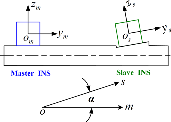
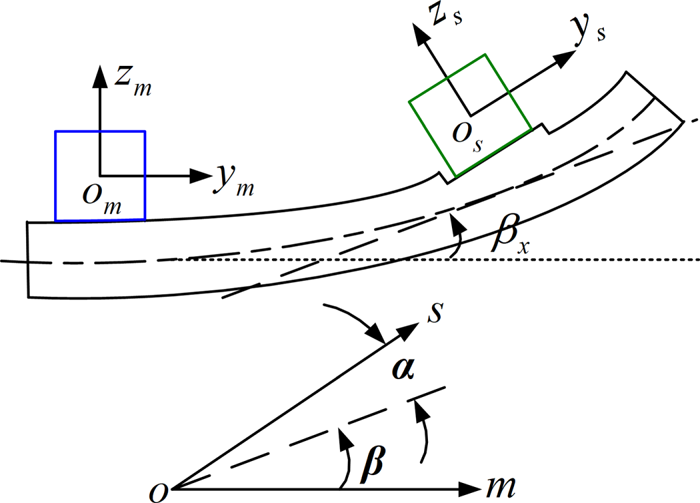
According to whether it changes with time, the angular deformation ${\mathbf \chi }$ can be divided into two parts, the static angular deformation ${\mathbf \alpha }$
 and the dynamic angular deformation ${\mathbf \beta }$
 , and their schematic diagrams are shown in Figures 1 and 2, respectively.
Schematic diagram of the static angular deformation

Schematic diagram of the dynamic angular deformation

2.1.1 Static angular deformation model
The static angular deformation, also known as the installation error angle, is modelled as (Gong et al., Reference Gong, Fan and Fang2014; Lu et al., Reference Lu, Fang, Liu, Gong and Wang2017):

2.1.2 Dynamic angular deformation model
The dynamic angular deformation is usually divided into the flexure angle in the low frequency and the angular vibration in the high frequency for modelling separately (Wang et al., Reference Wang, Zhao and Xie2011; Yue et al., Reference Yue, Li, Zhang, Liu and Wang2013).
(1) Flexure angle model
Considering that the flexure angles ${\eta _x},{\eta _y},{\eta _z}$ in the three directions are independent of each other, the flexure angles can be modelled as (Lu et al., Reference Lu, Fang, Liu, Gong and Wang2017; Gong and Chen, Reference Gong and Chen2019):

where ${\omega _{\eta ,i}}$ is the flexure angle rate, ${\lambda _i} = {{2.146} / {{\tau _i}}}$
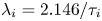 , ${\tau _i}$
 is the correlation time, ${w_{\eta ,i}}$
 is the Gaussian white noise with zero mean, and its variance ${Q_{\eta ,i}}$
 satisfies

where $\sigma _{\eta ,i}^2$ is the variance of the flexure angle ${\eta _i}$
 .
(2) Angular vibration model
Considering that the angular vibrations ${\vartheta _x},{\vartheta _y},{\vartheta _z}$ in the three directions are independent of each other, the angular vibrations can be modelled as (Wang et al., Reference Wang, Zhao and Xie2011; Yue et al., Reference Yue, Li, Zhang, Liu and Wang2013):

where ${A_i}$ is the amplitude of the angular vibration, ${f_i}$
 is the vibration frequency, and ${\varphi _i}$
 is the initial phase.
Since the installation error angle and flexure angle are usually one or two orders of magnitude higher than the angular vibration, the traditional transfer alignment filter usually expands the installation error angle, flexure angle and flexure angle rate into the state vector for estimation and compensation (Yue et al., Reference Yue, Li, Zhang, Liu and Wang2013). For the angular vibration, the traditional transfer alignment filter regards it as the measurement noise, and further adjusts the measurement noise variance to match the actual vibration intensity, to reduce the influence of angular vibration on the transfer alignment accuracy.
2.2 Traditional transfer alignment method
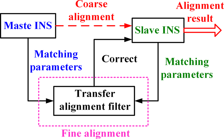
To take both rapidity and accuracy into account, the traditional transfer alignment method is usually divided into two stages: coarse alignment and fine alignment. The block diagram of the traditional transfer alignment method is shown in Figure 3.
Block diagram of the traditional transfer alignment method

In the coarse alignment stage, the attitude of the master INS is directly transferred to the slave INS in a ‘one-time’ way, so as to quickly obtain a rough attitude of the slave INS. In the fine alignment stage, the transfer alignment filter is used to further estimate and correct the coarse alignment error, so as to obtain a more accurate attitude of the slave INS.
After the coarse alignment, the relative misalignment angle between the master and slave INSs is quickly controlled in a small angle range. On this basis, considering the influence of various error factors, such as inertial sensor errors and angular deformation, and using the ‘velocity plus attitude’ matching method, the linear system error equation as shown is established (Kain and Cloutier, Reference Kain and Cloutier1989; Qin et al., Reference Qin, You and Song2010; Lu et al., Reference Lu, Fang, Liu, Gong and Wang2017; Li et al., Reference Li, Wang, Lu and Li2019):


where the state vector ${\boldsymbol{X}_1}$ , measurement vector ${\boldsymbol{Z}_1}$
 , process noise vector ${\boldsymbol{W}_1}$
 , measurement noise vector ${\boldsymbol{V}_1}$
 , system matrix ${\boldsymbol{A}_1}$
 , process noise driving matrix ${\boldsymbol{G}_1}$
 , measurement matrix ${\boldsymbol{H}_1}$
 and measurement noise distribution matrix ${\boldsymbol{D}_1}$
 could be determined as follows:


where ${\boldsymbol \varphi }_\textrm{s}^n = {[{\phi _{\textrm{s,E}}},{\phi _{\textrm{s,N}}},{\phi _{\textrm{s,U}}}]^\textrm{T}}$ and $\delta {v_{\textrm{s,E}}},\delta {v_{\textrm{s,N}}},\delta {v_{\textrm{s,U}}}$
 are the attitude misalignment angle and velocity error of slave INS, respectively; ${\boldsymbol\varepsilon }_\textrm{s}^s = {[{\varepsilon _{\textrm{s},x}},{\varepsilon _{\textrm{s},y}},{\varepsilon _{\textrm{s},z}}]^\textrm{T}}$
 and $\boldsymbol{w}_{{\varepsilon _\textrm{s}}}^s = {[{w_{{\varepsilon _\textrm{s}},x}},{w_{{\varepsilon _\textrm{s}},y}},{w_{{\varepsilon _\textrm{s}},z}}]^\textrm{T}}$
 are the constant drift and random drift of gyroscope in the slave INS, respectively; ${\nabla _{\textrm{s},x}},{\nabla _{\textrm{s},y}},{\nabla _{\textrm{s},z}}$
 and ${w_{{\nabla _\textrm{s}},x}},{w_{{\nabla _\textrm{s}},y}},{w_{{\nabla _\textrm{s}},z}}$
 are the constant bias and random bias of accelerometer in the slave INS, respectively; ${\hat{v}_{\textrm{m,E}}},{\hat{v}_{\textrm{m,N}}},{\hat{v}_{\textrm{m,U}}}$
 and ${\hat{v}_{\textrm{s,E}}},{\hat{v}_{\textrm{s,N}}},{\hat{v}_{\textrm{s,U}}}$
 are the velocities calculated by the master and slave INSs, respectively; ${Z_{\textrm{DCM,1}}}(i,j)$
 is the i th row and j th column element of the attitude matching measurement matrix ${\boldsymbol{Z}_{\textrm{DCM,1}}} = \hat{\boldsymbol{C}}_m^n{(\hat{\boldsymbol{C}}_s^n)^\textrm{T}}$
 ; $\hat{\boldsymbol{C}}_m^n$
 and $\hat{\boldsymbol{C}}_s^n$
 are the attitude matrices calculated by the master and slave INSs, respectively; ${\boldsymbol \varphi }_\textrm{m}^n = {[{\phi _{\textrm{m,E}}},{\phi _{\textrm{m,N}}},{\phi _{\textrm{m,U}}}]^\textrm{T}}$
 and $\delta {v_{\textrm{m,E}}},\delta {v_{\textrm{m,N}}},\delta {v_{\textrm{m,U}}}$
 are the attitude misalignment angle and velocity error of master INS, respectively; ${\boldsymbol{\varOmega}}$
 and $\boldsymbol{F}$
 are the anti-symmetric matrices corresponding to $- {\boldsymbol \omega }_{ie}^n$
 and specific force ${\boldsymbol{f}^n}$
 ,respectively; ${\boldsymbol \omega }_{ie}^n$
 is the rotational angular velocity of the earth; and ${\boldsymbol{B}_1} = \textrm{diag}[ - \beta _x^2, - \beta _y^2, - \beta _z^2]$
 and ${{\boldsymbol{B}}_2} = \textrm{diag}[ - 2{\beta _x}, - 2{\beta _y}, - 2{\beta _z}]$
 are composed of parameters of flexure angle model.
It can be seen that the traditional transfer alignment method mainly has the following two problems:
(1) The linear system error equation is established on the premise that the coarse alignment error is a small angle. However, on the moving base, due to the influence of various complex factors, such as installation error and flexural deformation, it is difficult to ensure the angular deformation between the master and slave INSs within a small angle range. The traditional coarse alignment method may cause the coarse alignment error to not satisfy the small angle condition, which affects the estimation accuracy and convergence speed of the state in the transfer alignment filter.
(2) Both the system matrix and process noise variance depend on the parameters of the preset Markov model. In fact, the dynamic angular deformation changes with the structural characteristics of carrier, manoeuvre condition and external random interference. Moreover, the complex dynamic angular deformation is difficult to accurately describe by a simple empirical model. Therefore, the transfer alignment accuracy decreases due to the mismatch between the preset empirical model and the actual dynamic angular deformation.
3. Scheme and realisation of innovative transfer alignment
3.1 Design of transfer alignment scheme
Aiming at these two problems faced by the traditional transfer alignment method, two solutions are proposed:
(1) Affected by a variety of complex factors, such as installation error and flexural deformation, it is difficult to ensure that the angular deformation is within a small angle range. Nevertheless, the gyroscopes in the master and slave INSs can respectively measure the angular motion of their respective bodies relative to the inertial space, and the dynamic angular deformation can be described by the relative angular motion between the master and slave INSs. Therefore, the difference of angular velocities measured by the gyroscopes in the master and slave INSs contains the information of dynamic angular deformation. Obviously, using the difference of angular velocities to estimate the actual angular deformation, the slave INS can be aligned within a certain accuracy range as soon as possible, so that the system error equation can meet the linear equation condition in the fine alignment stage.
(2) The complex dynamic angular deformation is difficult to accurately describe by a simple empirical model, but the error characteristics of inertial sensors are relatively stable in a short transfer alignment time. Therefore, starting from the error characteristics of the gyroscopes in the master and slave INSs, the error model of angular deformation can be established, and further the angular deformation error can be accurately estimated and corrected in real time by the transfer alignment filter.
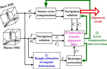
Based on these two solutions, a rapid and accurate transfer alignment scheme without relying on the empirical model is designed. The block diagram of the designed scheme is shown in Figure 4.
Block diagram of the rapid and accurate transfer alignment scheme

The designed scheme mainly includes the following three parts:
$\unicode{x2460}$
 Rough estimation of angular deformation. The rough initial value ${\hat{{\boldsymbol \chi }}_0}$ is calculated according to the angular velocities (i.e. $\tilde{{\boldsymbol \omega }}_{im}^m$ and $\tilde{{\boldsymbol \omega }}_{is}^s$) and specific forces (i.e. ${\tilde{\boldsymbol{f}}^m}$ and ${\tilde{\boldsymbol{f}}^s}$), and then the angular deformation is updated in real time by using the difference between the angular velocities $\tilde{{\boldsymbol\omega }}_{im}^m$ and $\tilde{{\boldsymbol \omega }}_{is}^s$.
$\unicode{x2461}$
Innovative transfer alignment filter. Firstly, an innovative transfer alignment filtering model is established using a ‘velocity plus attitude’ matching method, where the installation error angle, flexure angle and flexure angle rate in the state vector are replaced by the angular deformation error $\delta {\boldsymbol \chi }$. Then, the difference between the velocities $\hat{\boldsymbol{v}}_\textrm{m}^n$ and $\hat{\boldsymbol{v}}_\textrm{s}^n$ is taken as the velocity matching parameter, and the attitude matching parameter is constructed by the attitude matrices $\hat{\boldsymbol{C}}_m^n$, $\hat{\boldsymbol{C}}_s^n$ and $\hat{\boldsymbol{C}}_s^m$. Finally, the innovative transfer alignment filter is used to estimate the state vector.$\unicode{x2462}$
Error compensation and correction. The estimations of attitude misalignment angle, inertial sensors constant bias and angular deformation error are used to compensate and correct the attitude matrix of the slave INS, the outputs of slave IMU and the rough estimation of angular deformation, respectively.


Obviously, by calculating the rough initial value of angular deformation and using the gyroscopes outputs to estimate the actual angular deformation in real time, the designed scheme can align the slave INS within a certain accuracy range as soon as possible. Moreover, the designed scheme uses the error model of angular deformation to replace the empirical angular deformation model, to overcome the problem that the transfer alignment accuracy may be reduced or even divergent caused by the mismatch of empirical model.
3.2 Rough estimation method of angular deformation
The time-varying angular deformation ${\boldsymbol \chi }$ and the angular velocity of slave INS relative to master INS satisfy the differential equation

where the relative angular velocity ${{\boldsymbol \omega }_{ms}}$ can be expressed as

where ${{\boldsymbol \omega }_{im}}$ and ${{\boldsymbol \omega }_{is}}$
 are the inputs sensed by the gyroscopes in the master and slave INSs, respectively.
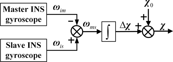
If the measurement errors are ignored, the outputs of the gyroscopes can be regarded as equal to their inputs. Hence, the outputs of gyroscopes in the master and slave INSs could be used to roughly estimate the angular deformation in real time. The schematic diagram of this idea is shown in Figure 5.
Schematic diagram of rough estimation for angular deformation

Firstly, the relative angular velocity ${{\mathbf \omega }_{ms}}$ can be calculated by the difference between the angular velocities ${{\boldsymbol \omega }_{im}}$
 and ${{\boldsymbol \omega }_{is}}$
 . Then, by integrating the calculated relative angular velocity ${{\boldsymbol\omega }_{ms}}$
 over time, the change of the angular deformation $\Delta {\boldsymbol \chi }$
 can be obtained. Finally, combined with the initial value ${{\boldsymbol \chi }_0}$
 , the angular deformation ${\boldsymbol \chi }$
 can be estimated in real time. Note that ${{\boldsymbol \chi }_0}$
 is not equal to ${\boldsymbol \alpha }$
 , because ${{\boldsymbol \chi }_0}$
 can be divided into two parts, the static angular deformation ${\boldsymbol \alpha }$
 and the initial value of dynamic angular deformation ${{\boldsymbol \beta }_0}$
 .
The direction cosine matrix is used to represent the relative attitude between the master and slave INSs. According to the principle of rough angular deformation estimation, the differential equation of the relative attitude matrix $\boldsymbol{C}_s^m$ can be written as

where ${\boldsymbol{\varOmega}}_{ms}^s$ , ${\boldsymbol{\varOmega}}_{is}^s$
 and ${\boldsymbol{\varOmega}}_{im}^m$
 represent the anti-symmetric matrices corresponding to ${\boldsymbol\omega }_{ms}^s$
 , ${\boldsymbol\omega }_{is}^s$
 and ${\boldsymbol \omega }_{im}^m$
 , respectively.
Equation (9) indicates that given the initial value of relative attitude matrix $\boldsymbol{C}_s^m(0)$ , the relative attitude matrix $\boldsymbol{C}_s^m$
 can be calculated in real time by the outputs of gyroscopes in the master and slave INSs. Hence, obtaining $\boldsymbol{C}_s^m(0)$
 is another problem to be solved.
At any time t, if the influence of lever arm effect is ignored, the specific forces ${\boldsymbol{f}^m}$ and ${\boldsymbol{f}^s}$
 sensed by the accelerometers in the master and slave INSs satisfy

where $\boldsymbol{C}_{m(0)}^{m(t)}$ and $\boldsymbol{C}_{s(t)}^{s(0)}$
 satisfy the following differential equations, respectively,


Since $\boldsymbol{C}_{m(0)}^{m(0)} = \boldsymbol{C}_{s(0)}^{s(0)} =\textbf{I}_{\textrm{3} \times \textrm{3}}$ , $\boldsymbol{C}_{m(0)}^{m(t)}$
 and $\boldsymbol{C}_{s(t)}^{s(0)}$
 can be updated in real time by using the outputs of gyroscopes in the master and slave INSs, respectively.
Left multiplying $\boldsymbol{C}_{m(t)}^{m(0)}$ , Equation (10) can be reorganised as

If the measurement errors are ignored, the outputs of the accelerometers can be regarded as equal to their sensitive specific forces. Hence, when the specific forces at two or more times are not collinear, the outputs of accelerometers in the master and slave INSs could be used to roughly estimate $\boldsymbol{C}_s^m(0)$ .
Right multiplying ${[\boldsymbol{C}_{s(t)}^{s(0)}{\boldsymbol{f}^s}(t)]^\textrm{T}}$ and integrating over time to reduce the influence of measurement errors, Equation (13) gives a least-square solution to $\boldsymbol{C}_s^m(0)$
 as (Wu et al., Reference Wu, Wu, Hu and Hu2011)

Combining Equations (11), (12) and (14), $\boldsymbol{C}_s^m(0)$ can be calculated according to the angular velocities and specific forces measured by the master and slave INSs. On this basis, according to Equation (9), $\boldsymbol{C}_s^m$
 can be updated in real time by the outputs of gyroscopes in the master and slave INSs. Finally, according to the one-to-one correspondence between $\boldsymbol{C}_s^m$
 and ${\boldsymbol\chi }$
 , the calculated $\boldsymbol{C}_s^m$
 can be transformed into the corresponding ${\boldsymbol \chi }$
 , so as to realise the rough estimation of angular deformation.
3.3 Error model of angular deformation
Further considering the measurement errors, the outputs of gyroscopes in the master and slave INSs can be expressed as


where $\tilde{{\boldsymbol \omega }}_{im}^m$ and $\delta {\boldsymbol \omega }_{im}^m$
 represent the output and measurement error of the gyroscope in the master INS, respectively. Similarly, $\tilde{{\boldsymbol \omega }}_{is}^s$
 and $\delta {\boldsymbol\omega }_{is}^s$
 represent the output and measurement error of the gyroscope in the slave INS, respectively.
Based on the designed rough estimation method of angular deformation, the estimated relative attitude matrix $\hat{\boldsymbol{C}}_s^m$ satisfies the differential equation

where $\tilde{{\boldsymbol \varOmega }}_{im}^m$ and $\tilde{{\boldsymbol \varOmega }}_{is}^s$
 represent the anti-symmetric matrices corresponding to $\tilde{{\boldsymbol \omega }}_{im}^m$
 and $\tilde{{\boldsymbol \omega }}_{is}^s$
 , respectively.
In fact, affected by the measurement errors of gyroscopes and the initial error of angular deformation $\delta {{\boldsymbol \chi }_0}$ , the estimated angular deformation inevitably contains the angular deformation error $\delta {\boldsymbol \chi }$
 . When $\delta {\boldsymbol \chi }$
 is a small angle, the relationship between the estimated relative attitude matrix $\hat{\boldsymbol{C}}_s^m$
 and real relative attitude matrix $\boldsymbol{C}_s^m$
 satisfies

where ${\boldsymbol{A}_{\delta {\mathbf \chi }}}$ represents the anti-symmetric matrix corresponding to $\delta {\boldsymbol \chi }$
 .
Substituting Equations (15), (16) and (18) into Equation (17), the differential equation can be written as

where $\delta {\boldsymbol{\varOmega}}_{im}^m$ and $\delta {\boldsymbol{\varOmega}}_{is}^s$
 represent the anti-symmetric matrices corresponding to $\delta {\boldsymbol \omega }_{im}^m$
 and $\delta {\boldsymbol \omega }_{is}^s$
 , respectively.
Differentiating the both sides of Equation (18), we can get

Substituting Equation (9) into Equation (20), the differential equation can also be written as

Combining Equations (19) and (21), we can get

Omitting the second-order small quantity of errors in Equation (22), the differential equation of the anti-symmetric matrix ${\boldsymbol{A}_{\delta {\mathbf \chi }}}$ can also be written as

According to the relationship between the anti-symmetric matrix and its corresponding vector, the differential equation of angular deformation error can be obtained from Equation (23) as

Since the accuracy of gyroscope in the master INS is one or two orders of magnitude higher than that of the gyroscope in the slave INS, the measurement error of gyroscope in the master INS can be ignored (Liu et al., Reference Liu, Xu, Liu and Wang2014; Si et al., Reference Si, Zhao, Lin and Zhang2018). If the measurement error of the gyroscope in the slave INS is modelled as the constant drift plus random drift, then Equation (24) can be simplified as

This error model is derived from the measurement error models of gyroscopes in the master and slave INSs. Because the error characteristics of inertial sensors are relatively stable in a short transfer alignment time, the error model of angular deformation can be used as the state model in the transfer alignment filter. It should be noted that when the stability of slave gyroscope is too poor, that is, the slave gyroscope error cannot be modelled as constant drift plus random drift within the transfer alignment time, this angular deformation error model cannot reflect the error characteristics of angular deformation. Under this condition, the estimation result of angular deformation error of the proposed method deteriorates and cannot be used.
4. Model of innovative transfer alignment method
4.1 State equation
According to the INS error equation and the error equation of angular deformation [i.e. Equation (25)], the state equation can be described as

where the state vector ${\boldsymbol{X}_2}$ , process noise vector ${\boldsymbol{W}_2}$
 , system matrix ${\boldsymbol{A}_2}$
 and process noise driving matrix ${\boldsymbol{G}_2}$
 could be determined as follows:


where $\delta {\chi _x},\delta {\chi _y},\delta {\chi _z}$ are the three components of angular deformation error $\delta {\boldsymbol \chi }$
 . Since the process noise is only related to the noise of slave IMU, the process noise parameters must be configured according to the accuracy of slave IMU during filtering.
4.2 Measurement equation
The attitude matrices $\hat{\boldsymbol{C}}_m^n$ and $\hat{\boldsymbol{C}}_s^n$
 calculated by the master and slave INSs and the estimated relative attitude matrix $\hat{\boldsymbol{C}}_s^m$
 are used to construct the attitude matching measurement matrix as

Affected by the attitude misalignment angles, the calculated attitude matrices $\hat{\boldsymbol{C}}_m^n$ and $\hat{\boldsymbol{C}}_s^n$
 can be expressed as


where $\boldsymbol{\varPhi }_\textrm{m}^n$ and $\boldsymbol{\varPhi }_\textrm{s}^n$
 represent the anti-symmetric matrices corresponding to ${\boldsymbol \varphi }_\textrm{m}^n$
 and ${\boldsymbol \varphi }_\textrm{s}^n$
 , respectively.
Substituting Equations (18), (28) and (29) into Equation (27), we can get

where ${\boldsymbol{Z}_{\textrm{DCM,2}}}$ can be expressed as the sum of the identity matrix and anti-symmetric matrix, and the vector corresponding to the anti-symmetric matrix can be expressed as

Take ${\boldsymbol{Z}_{\textrm{att,2}}}$ as the attitude matching parameter, and make the difference between the velocities calculated by the master and slave INSs to obtain the velocity matching parameter, then the measurement vector ${\boldsymbol{Z}_2}$
 is selected as

where ${Z_{\textrm{DCM,2}}}(i,j)$ is the i th row and j th column element of ${\boldsymbol{Z}_{\textrm{DCM,2}}}$
 .
The measurement equation can be described as

where the measurement noise vector ${\boldsymbol{V}_2}$ and measurement matrix ${\boldsymbol{H}_2}$
 can be determined as

The innovative transfer alignment filtering model can be obtained by combining Equations (26) and (32). Compared with the traditional transfer alignment filtering model, the innovative transfer alignment filtering model has the following advantages:
(1) The innovative transfer alignment filtering model is designed according to the error model of angular deformation, rather than the empirical model of angular deformation, so the innovative transfer alignment filtering model gets rid of the dependence on the empirical model.
(2) Since it no longer relies on the empirical model of angular deformation, the innovative transfer alignment filtering model avoids the complicated parameter identification.
(3) The computation burden of the Kalman filter is approximately proportional to ${a^3} + b{a^2}$
, where a and b represent the dimensions of state vector and measurement vector, respectively (Lu et al., Reference Lu, Fang, Liu, Gong and Wang2017). The innovative transfer alignment filtering model reduces the dimension of state vector from 21 to 15, so the computation burden is reduced by $1 - ({{{{15}^3} + 6 \times {{15}^2})} / {({{21}^3} + 6 \times {{21}^2})}} = 60.32\%$.


5. Simulation and experiment
5.1 Simulation
The weak manoeuvrability of a vehicle greatly limits the transfer alignment performance of vehicle-mounted weapons. Therefore, a transfer alignment mode which utilises the rotation of the launcher to improve the observability of the system has emerged (Qin et al., Reference Qin, You and Song2010; Wang et al., Reference Wang, Yang, Wen and Yang2013). The following will verify the performance of the proposed method based on this vehicle-mounted transfer alignment mode.
5.1.1 Simulation conditions
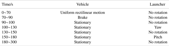
The vehicle trajectory is designed by using three continuous manoeuvring processes of vehicle braking, launcher yaw and launcher pitch. The total simulation time is 300 s. Table 1 shows the specific manoeuvre statuses. The initial velocity is 20 m/s, and the initial longitude, latitude and altitude are 116°E, 40°N and 100 m, respectively. The initial pitch, roll and yaw angle of the vehicle are 0°, 0° and −30°, respectively. The magnitude of acceleration when the vehicle brakes is 1 m/s2. The launcher is parallel to the longitudinal axis of the vehicle before rotation. When the launcher yaws or pitches, its angular rate is 3 °/s.
Manoeuvre statuses

The sampling frequencies of the inertial sensors in the master and slave INSs are all 100 Hz. The parameters of the slave INS are set as follows: the gyroscope constant drift is 0⋅1 °/h, the gyroscope random walk is $0.02^\circ{/}\sqrt{\textrm{h}}$ , the accelerometer constant bias is $500\,\mu g$
 and the accelerometer random walk is $100\,\mu g/\sqrt {\textrm{Hz}}$
 . The navigation parameters provided by the master INS are set in the form of true value plus white noise, where the standard deviation of velocity error is 0⋅02 m/s, and the standard deviation of attitude error is $\mathrm{1^{\prime}}$
 .
The angular deformation is set to the following three typical cases.
Case 1: The static angular deformation is set to ${\alpha _x} = \textrm{18}^\circ$ , ${\alpha _y} = \textrm{25}^\circ$
 , ${\alpha _z} = \textrm{3}0^\circ$
 to verify the performance of the proposed method under the condition of large angular deformation. The dynamic angular deformation is set as a second-order Markov process, where the standard deviation of the flexure angle is ${\sigma _{\eta ,x}} = \textrm{2}0^{\prime},{\sigma _{\eta ,y}} = 10^{\prime},{\sigma _{\eta ,z}} = 30^{\prime}$
 , and the correlation time is ${\tau _x} = \textrm{1}00\textrm{s},{\tau _y} = 1\textrm{50s},{\tau _z} = \textrm{2}00\textrm{s}$
 .
Case 2: To contrast the performance of the proposed and traditional methods under the condition of small angular deformation, the static angular deformation is set to ${\alpha _x} = \mathrm{18^{\prime}},{\alpha _y} = \mathrm{25^{\prime}},{\alpha _z} = \mathrm{12^{\prime}}$ . The dynamic angular deformation is set as a second-order Markov process, where the standard deviation of the flexure angle is ${\sigma _{\eta ,x}} = \mathrm{2^{\prime}},{\sigma _{\eta ,y}} = \mathrm{1^{\prime}},{\sigma _{\eta ,z}} = 3^{\prime}$
 , and the correlation time is ${\tau _x} = \textrm{4s},{\tau _y} = \textrm{5s},{\tau _z} = \textrm{6s}$
 .
Case 3: To contrast the performance of the proposed and traditional methods when the empirical flexure angle model is mismatched, the dynamic angular deformation is set as a sine function, where the amplitude is ${A_x} = 4^{\prime},{A_y} = 6^{\prime},{A_z} = 8^{\prime}$ , the frequency is ${f_x} = 0.05\,\textrm{Hz},{f_y} = 0.08\,\textrm{Hz},{f_z} = 0.1\,\textrm{Hz}$
 , and the initial phase is a random value in the range of $0\mathrm{\sim }2\pi$
 . The static angular deformation is the same as Case 2.
5.1.2 Simulation results and analysis
(1) Under the condition of large angular deformation
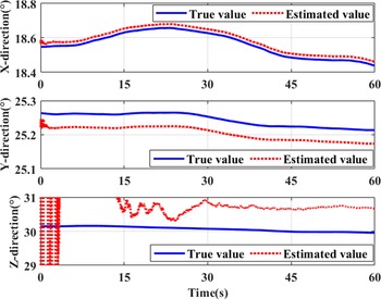
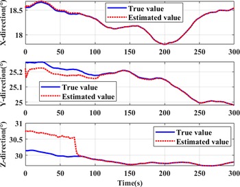
Firstly, the feasibility of the rough estimation method of angular deformation is evaluated. The rough estimation results of angular deformation in the first 60 s are shown in Figure 6. As shown in Figure 6, even under the condition of large-angle deformation, the proposed method can control the coarse alignment error within a small angle range rapidly. The integration time in the calculation of angular deformation initial value is set to 60 s, and the data during this period is stored. After the angular deformation initial value is calculated at 60 s, the transfer alignment is started from the 0th second by using the stored data. The estimation results of angular deformation in the whole transfer alignment are shown in Figure 7. When the launcher starts to rotate in the 100th second to make the system completely observable, the estimated value of angular deformation in all three directions tends to its true value. Obviously, the proposed method can accurately estimate the large angular deformation.
Rough estimation results of angular deformation (Case 1)

Estimation results of angular deformation after correction (case 1)

Attitude misalignment angle (Case 1)

Velocity error (Case 1)

Estimation of gyroscope constant drift (Case 1)

Estimation of accelerometer constant bias (Case 1)

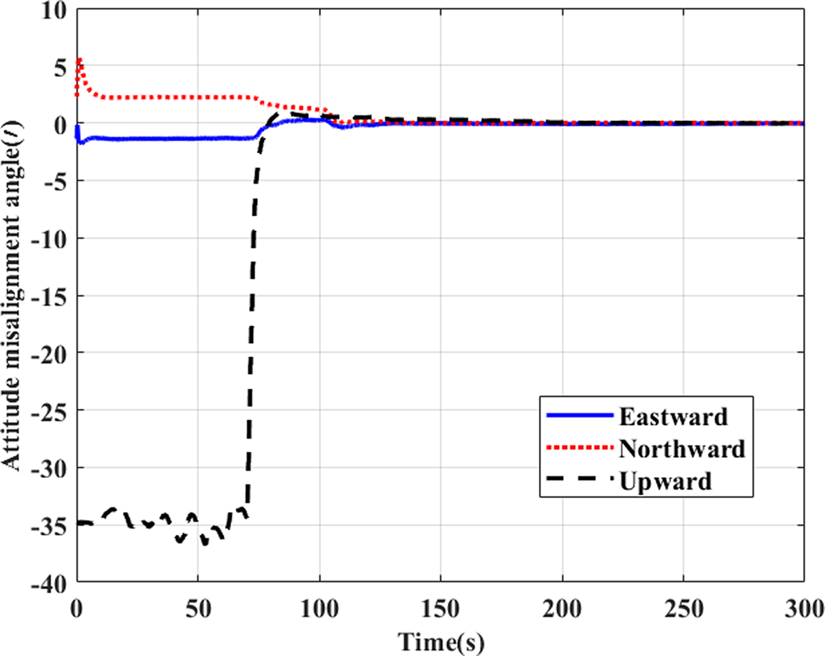
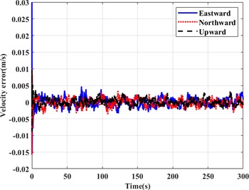
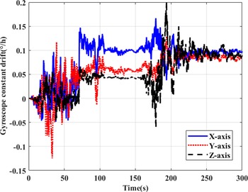
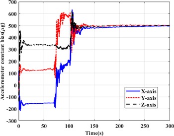
Figures 8–11 show that the proposed method can still effectively estimate the attitude misalignment angle, velocity error, gyroscope constant drift and accelerometer constant bias under the condition of large-angle deformation. Obviously, the proposed method can overcome the influence of large angular deformation on the transfer alignment performance, and these results also verify the effectiveness of the proposed innovative transfer alignment filtering model.
(2) Under the condition of small angular deformation
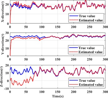
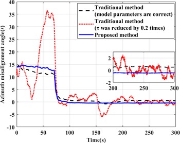
Figure 12 shows that the proposed method can also accurately estimate the angular deformation under the condition of small-angle deformation. Figure 13 shows that the azimuth misalignment angle in the proposed method converges quickly as the system is completely observable. When the parameters of the empirical flexure angle model are completely correct, the alignment accuracy of the traditional method is equivalent to the proposed method. However, when the correlation time is reduced by 0⋅2 times, the accuracy of the empirical flexure angle model decreases, so does the alignment accuracy of the traditional method. The comparison shows that the proposed method still maintains high transfer alignment accuracy, while the alignment accuracy of traditional method decreases due to the decrease of empirical model accuracy.
(3) Under the condition of empirical flexure angle model mismatch
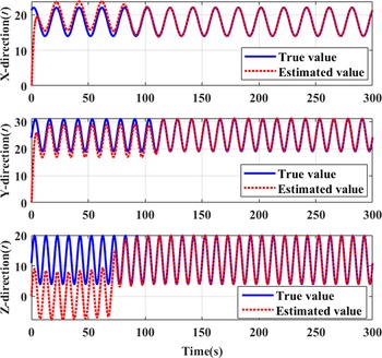
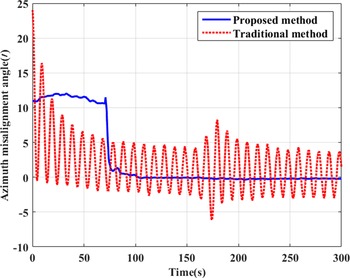
As shown in Figures 14 and 15, even if the dynamic angular deformation varies with time in the form of a sine function, the proposed method can still accurately estimate the angular deformation. However, when the empirical flexure angle model is mismatched, the traditional method cannot accurately estimate the flexure angle, which makes the attitude misalignment angle oscillate with the actual dynamic angular deformation. The comparison shows that the proposed method can still achieve the fast and accurate transfer alignment of slave INS, while the traditional method cannot converge the attitude misalignment angle due to the empirical model mismatch.
Estimation of angular deformation after correction (Case 2)

Comparison of azimuth misalignment angle (Case 2)

Estimation of angular deformation after correction (Case 3)

Comparison of azimuth misalignment angle (Case 3)

There is little difference between the estimations of the proposed method in three cases, so the state estimations in Case 2 and Case 3 are not given here.
5.2 Experiment
5.2.1 Experiment conditions
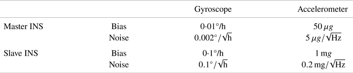
To further verify the feasibility of the proposed method in practical application, a vehicle-mounted experiment is carried out. The sampling frequencies of the master and slave INSs carried in the experiment are all 100 Hz, and the main parameters are listed in Table 2.
Main parameters of the master and slave INSs

To evaluate the performance of the proposed method, two sets of global navigation satellite system (GNSS) receivers are configured at the installation position of the master and slave INSs, respectively. The attitude parameters of slave-INS/GNSS integrated navigation system are used as reference to evaluate the attitude misalignment angle of slave INS in the transfer alignment. Moreover, using the attitude parameters of master-INS/GNSS and slave-INS/GNSS integrated navigation systems, the angular deformation can be calculated indirectly. Taking this calculation result as the reference value, the estimation result of angular deformation in the proposed method can be evaluated.
5.2.2 Experiment results and analysis
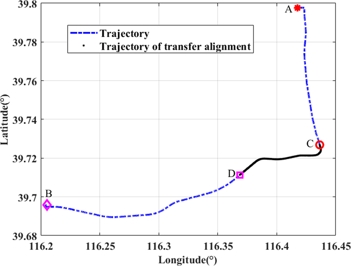
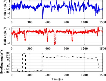
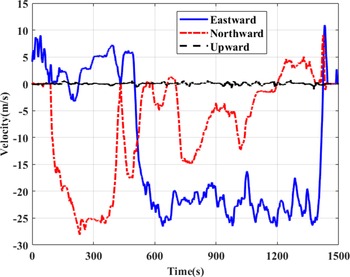
The trajectory, attitude and velocity of the vehicle are shown in Figures 16–18, respectively. The vehicle starts from Point A and stops at Point B, and the total time is 1,500 s. Select a trajectory of 500th second to 800th second to complete the transfer alignment. During this time, the vehicle runs from Point C to Point D. Figures 16–18 are obtained from the master-INS/GNSS integrated navigation system.
Vehicle trajectory

Attitude of vehicle

Velocity of vehicle

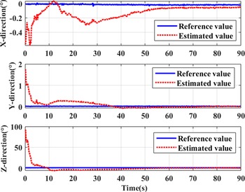
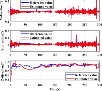
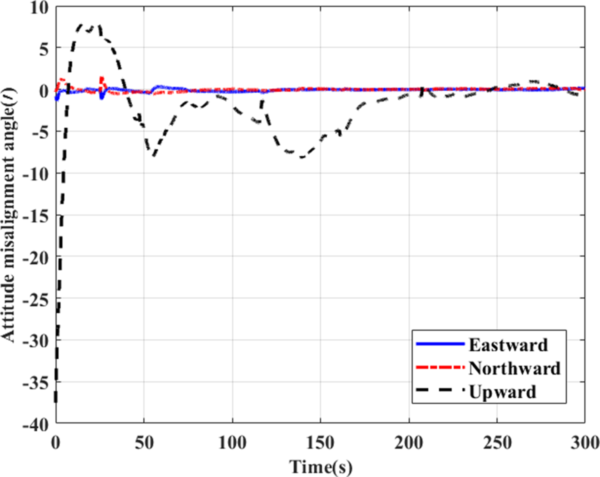
As shown in Figures 19–21, the rough estimation results of angular deformation, the corrected estimation results of angular deformation and the attitude misalignment angle of the proposed method are shown, respectively.
Calculation results of initial value of angular deformation

Estimation results of angular deformation after correction

Attitude misalignment angle

As shown in Figure 19, after the vehicle turns in the 10th second, the error of angular deformation rough estimation quickly converges to a small angle range. Setting the integration time in the calculation of angular deformation initial value to 60 s, the estimation results of angular deformation by the proposed method are shown in Figure 20. The proposed method utilises the outputs of gyroscopes in the master and slave INSs to roughly estimate the angular deformation, and accurately estimates and corrects the angular deformation error based on the error model of angular deformation. Therefore, the estimation results of angular deformation can converge to their reference values. Figure 21 shows the attitude misalignment angle curve of the proposed method. It can be seen that the proposed method could realise rapid and accurate transfer alignment, so it is feasible in practical application.
6. Conclusions
The speed and accuracy of transfer alignment are directly related to the preparation time and navigation accuracy of the slave INS. However, the traditional transfer alignment methods have poor rapidity and accuracy due to the empirical model mismatch or the low measurement accuracy of external equipment. To solve this problem, a rapid and accurate transfer alignment method without relying on the empirical model of angular deformation is proposed. After theoretical analysis and performance verification, the conclusions are as follows:
(1) The proposed method is derived from the internal relationship between the angular deformation and relative angular velocity, and is obtained from the measurement error models of gyroscopes in the master and slave INSs. Therefore, the proposed method can get rid of the dependence on an empirical angular deformation model.
(2) The coarse alignment of the proposed method is achieved by using the outputs of gyroscopes and accelerometers in the master and slave INSs to roughly estimate the angular deformation. Even if the angular deformation between the master and slave INSs is large, the proposed method can control the coarse alignment error in a small angle range rapidly, so as to improve the estimation accuracy and convergence speed of the state in the transfer alignment filter.
(3) The proposed method utilises the angular deformation error as the state vector instead of the installation error angle, flexure angle and flexure angle rate in the traditional transfer alignment filtering model, to reduce the order and computation burden of the transfer alignment filter.
(4) In the proposed method, the rough estimation of angular deformation is obtained from the outputs of gyroscopes in the master and slave INSs, and the angular deformation error is accurately estimated and compensated in real time based on the error model of angular deformation. Through the previous two steps, the accuracy of transfer alignment is improved.
Compared with traditional methods, the proposed method not only gets rid of the dependence on empirical angular deformation model, but also realises the rapid and accurate initial alignment of the slave INS without adding any external measurement equipment. Therefore, the proposed method has broad application prospects.
Acknowledgment
This work was supported by the Natural Science Foundation of China (NSFC) (grant number 61673040 and 61074157), the Joint Projects of NSFC-CNRS (grant number 61111130198), the Key basic research projects (grant number 2020-JCJQ-ZD-136-12), the Aeronautical Science Foundation of China (grant number 2015ZC51038 and 20170151002) and the Project of the Experimentation and Technology Research (1700050405). The work is also supported by the Open Research Fund of State Key Laboratory of Space–Ground Integrated Information Technology under grant number 2015-SGIIT-KFJJ-DH-01.