I. INTRODUCTION
Mullite has excellent high temperature strength and creep resistance, well-behaved infrared transmission, and good thermal and chemical stability. Reference Kriven, Palko, Sinogeikin, Bass, Sayir, Brunauer, Boysen, Frey and Schneider1–Reference Kanzaki, Tabata, Kumazawa and Ohta3 Mullite coatings have been widely used as the thermal or environment barrier coating. Reference Lee4,Reference Miller5 To meet the demands, it is highly desired to obtain dense mullite coatings without cracking, and with relatively large thickness. However, limited success has been met with in processing dense and crack-free mullite coatings. For example, deposition of mullite coatings using plasma-spray or chemical vapor deposition method often results in poor microstructures such as nonuniformity, microcracks, excessive grain growth, and high porosity. Reference Kulkarni, Wang, Basu and Sarin6–Reference Mulpuri and Sarin9
The sol–gel method has the unique advantage of processing ceramic materials of various chemical compositions directly from liquids, making it attractive to achieve dense and uniform ceramic coatings and films. Reference Brinker and Scherer10,Reference Roy, Das and Maitra11 In previous research, mullite coatings were synthesized from a colloidal sol–gel precursor using boehmite and TEOS, or from aluminum nitrates (AN) and TEOS. Reference Chen and Wei12 The mullite phase was often not observed until firing at above 1200 °C, and the coating still contained impurity phases. Reference Wang, Yang, Li, Lin and Chi13–Reference Jayasankar, Anilkumar, Smitha, Mukundan, Madhusoodana and Warrier15 Furthermore, abnormal grain growth occurred as a consequence of the high temperature sintering. Reference Chen and Wei12 To ensure the high temperature mechanical properties, it is important to eliminate spinel phase and lower the mullite formation temperatures to relatively low temperatures (e.g., <1200 °C) to avoid excessive grain growth. Reference Selvaraj, Komarneni and Roy16–Reference Ban, Hayashi, Yasumori and Okada18 So far, achieving such a goal seems to be difficult.
Depositing thin films using the conventional sol–gel dip coating technique often has the challenge of cracking when the thickness exceeds the critical thickness, due to the residual tensile stress caused by the shrinkage of the gel film during firing. Reference Kozuka, Takenaka, Tokita, Hirano, Higashi and Hamatani19–Reference Chen, Burtovyy, Kornev, Luzinov, Xu and Peng21 The typical critical thickness for the sol–gel dip coating method is around 100 nm. Reference Brinker, Hurd, Schunk, Frye and Ashley22,Reference Chen and Chen23 Many attempts have been made to increase the critical thickness. These methods include the modification of the hydrolytic salts with chelating ligands, and use of high molecular weight solvents and organic polymers, which promotes structural relaxation to form thick films without cracks. Reference Kozuka and Takenaka24–Reference Du and Ma29 The sol–gel particle coating method, or sometimes called “composite ceramic sol–gel processing” technique, brings about new possibilities in fabricating crack-free ceramic coatings of improved thickness. In this method, an metal–organic precursor can be used as the dispersant and binder. Ceramic powder is mixed with the sol to form a stable suspension. This method has been widely used to produce crack-free piezoelectric films. Reference Barrow, Petroff, Tandon and Sayer30–Reference Corker, Zhang, Whatmore and Perrin33 The resulting thick films are sometimes referred as the ‘0–3’ composite films, which reflects the structure of zero-dimensional ceramic particles surrounded by three-dimensionally connected sols. The sol–gel particle coating method can benefit from the unique structure of spatially distributed components with different physical and chemical properties: (i) Formation of ceramic sol and gel which bridges particles, leading to firmly bonded particles and less cracks; (ii) As compared to the coatings derived from sols, significantly less shrinkage of the composite coating due to the presence of ceramic particles, leading to a lower stress.
However, the composite films often suffer poor mechanical properties due to the porous and nonuniform microstructure. Reference Wang, Zhu, Zhao and Tan31 The infiltration process, which uses ceramic sols to fill up the pores, has been used to reduce the porosity. Reference Wang, Zhu, Zhao and Tan31 Such procedure often requires multiple heat treatment cycles to finally achieve dense films. Reference Wang, Zhu, Zhao and Tan31 In practical applications, it is desired to obtain high density films with single or less-recycled deposition. As pressureless sintering is generally applied to densify coatings, the process often involves low heating and cooling rate than other sintering process (e.g., Spark Plasma Sintering & flash sintering) at high temperatures, which sometimes results in uncontrollable grain growth and poor microstructures. Reference Erk, Deschaseaux and Trice34 Therefore, processing dense and crack-free ceramic coatings remains great challenges.
In this work, we report a hybrid sol/particle coating method to form crack-free dense mullite films. Amorphous mullite nano-particles were prepared from a mullite sol–gel precursor. A complete amorphous nanocomposite film was deposited from the sol/particle mixture. Different from the composite coating method reported before, amorphous mullite particles mixed with the mullite precursor resulted in crack-free thick films which can be sintered to fully dense at low temperature.
II. EXPERIMENTAL PROCEDURE
A. Materials preparation
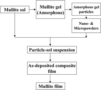
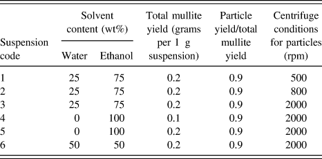
The processing steps for mullite coatings are shown in Fig. 1. A homogeneous mullite precursor was synthesized according to our previous study. Reference Chen, Zhang, Tsai, Kornev, Luzinov, Fang and Peng35 Amorphous mullite nanoparticles were obtained after the following steps. In the first step, mullite sol (with ∼40 wt% yield of ceramic) was heated to 300, 500, or 800 °C at a heating rate of 20 °C/min to obtain a porous solid gel. The gel was crushed and grounded into powders. The obtained powders were then ball-milled in ethanol for 24–72 h to form a fine particle suspension. The suspension was centrifuged to select the particles of fine sizes. The centrifuge speeds ranged from 500 to 2000 rpm. The obtained mullite nanoparticles were dried, weighted, and then mixed with mullite sol to form a suspension. High energy ultra-sonication (Vibra Cell VC 500, Sonics, Connecticut) was used for 2 h to achieve a good dispersion. For all suspensions, the ratio between the weight of particle and mullite yield of the sol was kept at 9:1. The content of solvents and mullite yield of the suspensions are summarized in Table I. The obtained suspension was dip-coated on a 2 cm × 1 cm × 0.5 mm single-side polished Si wafer at ambient temperature with a RH (relative humidity) level of 50–60%. The withdrawal speeds used in dip-coating ranged from 0.51 to 6.35 mm/s to obtain coatings with different thickness. The films were dried for 24 h in a desiccator at ambient temperature before heat treatment. The coatings were heat treated in air at 5 °C/min to the target temperature between 1000 and 1200 °C for 2 h.
Schematic experimental approach.

The solvent contents and mullite yields of the dip-coating suspensions.

B. Characterization
Particle size distribution was measured by using Laser Diffraction Particle Size Analyzer (LA-910, HORIBA Instrument Inc., Irvine, California). The coating thickness measurement was carried out in atomic force microscopy (AFM; Dimension 3100 AFM, Veeco Inc, Plainview, New York). Before firing, a scratch through the coating was applied to the film using a sharp blade. The thickness was determined by scanning the profile across the scratch and calculating the depth of the scratch. The surface tension measurements were performed in a Cahn instrument (DCA-322 analyzer, Thermo Cahn Instruments, Madison, Wisconsin). The crystalline phases were identified using X-ray diffraction (XRD; Rigaku Co. Ltd., Tokyo, Japan) and the film microstructure was characterized using scanning electron microscopy (SEM; Hitachi S4800, Hitachi Ltd., Tokyo, Japan). The thermal characteristics were studied at different heating rate under flowing air condition using DTA (DTA7, Perkin Elmer, Waltham, Massachusetts), and TGA (TGA7, Perkin Elmer).
III. RESULTS
A. Thermal decomposition and phase identification
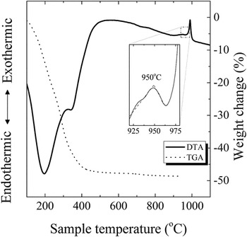
In the DTA traces, shown in Fig. 2, the endothermic peaks at 100–200 °C were attributed to the boiling of absorbed solvent and low molecular weight organics. The endothermic peak at 300–400 °C was due to the decomposition of polymer chains. Reference Okada, Yasohama, Hayashi and Yasumori36 The exothermic peak at around 1000 °C corresponded to the crystallization of mullite phase. These peaks are consistent with other reports. Reference Okada, Yasohama, Hayashi and Yasumori36,Reference Song37 The TGA curve (Fig. 2) showed continuous weight loss in two stages. The first stage occurred at below 200 °C was due to vaporization of residual solvent and low molecular weight organics. The second stage occurred at around 250–350 °C was caused by the burn out of organics and formation of amorphous oxide. Overall, fast weight loss occurred at 100–400 °C. Above 400 °C, the weight remained almost constant. The zoomed-in curve at ∼950 °C of Fig. 2 shows a glass transition region before crystallization of the gel. The transition temperature (T g) is arbitrarily defined as the temperature corresponding to the intersection of the two linear portions adjoining the transition elbow. Reference Vázquez, López-Alemany, Villares and Jiménez-Garay38–Reference Hu and Ye40 Detailed discussion will be given later in Sec. IV. C.
DTA (solid) and TGA (dashed) curves of mullite gel heat treated at 20 °C/min. The internal frame shows the observation of glass transition close to the crystallization temperature of mullite.

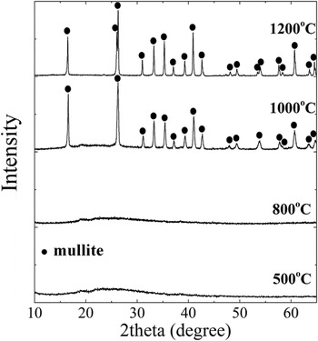
The XRD results of the dried mullite gel after heat-treatment at 500, 800, 1000, and 1200 °C was shown in Fig. 3. The heated gel powders remain amorphous below 1000 °C. The identified peaks indicated the well-defined pure mullite phase without spinel phase. In the sol–gel processing, elimination of the spinel formation is challenging and important. Reference Selvaraj, Komarneni and Roy16–Reference Ban, Hayashi, Yasumori and Okada18
XRD patterns of mullite gel heat treated at different temperatures.

B. Formation of coatings
1. Characterization of the gel nanoparticles
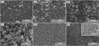
Amorphous mullite gel particles were obtained from mullite gel after heat treatment and ball-milling. The microstructure of the gel particles is shown in Fig. 4. After the same duration (24 h) of ball milling, the gel particles had the smallest average size if heat-treated at 300 °C and the greatest at 800 °C. Further extending the ball-milling time to 72 h resulted in a reduction in the particle size [Fig. 4(d)]. Although the gel powders heat treated at 300 °C had the finest particle size, the decomposition of mullite gel at this temperature was incomplete, and significant amount of polymer still remained. Since the major goal of using solid nanoparticles in the suspension is to minimize the volumetric shrinkage caused by gel decomposition, the gel powders obtained at 500 °C were chosen for processing of mullite coatings.
Amorphous mullite particles obtained after ball-milling. The powders were preheat treated at (a) 300 °C (b) 500 °C (c) 800 °C and ball-milled for 24 h. The rest were preheat treated at 500 °C and ball-milled for 72 h (d), followed by centrifuge at (e) 800 and (f) 2000 rpm.

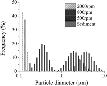
Figure 5 shows the size distribution of the dried mullite gel particles after heat treatment at 500 °C and ball-milling for 72 h, followed by centrifuge at 500, 800, and 2000 rpm. Morphologies of the gel particles after centrifuge at 800 and 2000 rpm are shown in Figs. 4(e) and 4(f). Those speeds lead to good separation of particle sizes with small overlap in the distribution curves. The size distribution for the residual sediment is also presented in Fig. 5. The mean sizes of 0.12, 0.34, 2.1, and 3.8 μm correspond respectively to the samples obtained by centrifuging at 2000, 800, 500 rpm and sedimentation. The result shows that reduction and selection of particle sizes by centrifuge is effective for ceramic gel particles.
Size distribution of mullite gel nanoparticles after heat treatment at 500 °C followed by centrifuge.

2. Film morphology
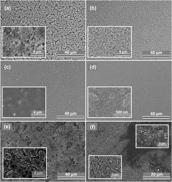
Figure 6 shows the microstructure of mullite films after calcination. The coatings obtained from suspension 1, 2, and 3 have uniform microstructure with different packing densities of particles. Porous microstructure was observed in coatings obtained from suspension 1 and 2, containing loosely packed particles and open pores. The typical sizes of pores are on the sub-micrometer to micrometer scale. In the coating obtained from suspension 1, some of the pores between particles segregate to form macroscopic trenches [Fig. 6(a)]. The size of pores reduces as particle size decreases. No significant macroscopic trenches were observed in coatings obtained from suspension 2 and 3. The coating obtained from suspension 3 has a higher packing density of particles without the observation of microscopic pores. The films sintered at 1200 °C [Fig. 6(d)] did not show microscopic pores or cracks.
Microstructure of mullite films derived from suspension 1–5. (thickness-suspension code): (a) >7 µm−1; (b) ∼1 µm−2; (c) & (d) ∼500 nm−3; (e) ∼300 nm−4 (f) ∼300 nm−5. Heat treatment temperatures: (a–c, e & f) 1000 °C; (d) 1200 °C.

Nonuniform coatings were obtained from suspension 4 and 5 [Figs. 6(e) and 6(f)]. The particles have significantly lower packing densities as compared to the one obtained from suspension 3, with the observation of sub-micrometer to nanometer sized pores between particles. Some of the pores formed channels, separating the nanoparticle into individual clusters. In coatings obtained from suspension 5, we observed heterogeneous microstructure and regional separation of fluid (sol) and nanoparticle phases [Fig. 6(f)]. This heterogeneity was caused by the lateral migration of fluid and segregation of the nanoparticles during the drying process, as liquid migrate toward regions of higher evaporative flux. Reference Harris, Hu, Conrad and Lewis41 In suspension 6, particle agglomerations were still observed by naked eyes after high energy sonication. Therefore it was not selected as candidate suspension for coating deposition.
C. Cracking and critical thickness
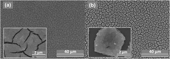
Figure 7 shows the cracked mullite films derived from suspension 3 after drying and calcination at 1000 °C. A single-step deposited film thickness above which cracking substantially occurs is often termed as “critical thickness” (τc). In our previous study, we demonstrated that the mullite films derived from sol–gel coating method has a τc value of 120 nm. Reference Chen, Burtovyy, Kornev, Luzinov, Xu and Peng21 The critical thickness value for ethanol system (suspension 4 & 5) was below 300 nm. The τc value for water-ethanol system (suspension 3) was 500–600 nm. The critical thickness for coatings obtained from suspension 2 was ∼1 μm. The critical thickness of coatings obtained from suspension 1 was beyond the range of our AFM (>∼7 μm). However, those coatings with τc > 1 μm are highly porous and of large roughness.
Cracked mullite films (thickness > 1 μm) processed from suspension 3. (a) Cracked at room temperature, but still showing the ‘strain-limited’ feature (b) cracked after firing at 1000 °C.

IV. DISCUSSION
A. Consolidation of particle and sol phases during drying
The features of being dense and crack free for ceramic coatings are especially important for corrosion protection. As most of the sol–gel derived coatings are obtained from pressureless sintering, the green body density is critical to the final density that can be achieved. It is generally accepted that green compacts with a higher green density can be sintered easily. Reference Milne, Patel and Dickinson42,Reference Ji, Lan and Xiao43 In the particle-sol coating process, consolidation of particles and sol phases during drying lead to different densities of the green body coatings before the heat treatments. In agreement with other report, the process of using nanoparticles in the suspension gives rise to high density of green body with extremely fine pore size, which can be on the order of a few nanometers. Reference Wang, Zhu, Zhao and Tan31 Consolidation of submicrometer and micrometer sized particle suspension in sols however often lead to a significantly lower density. Reference Wang, Zhu, Zhao and Tan31
The consolidation process is unlikely initiated by sedimentation. To estimate the lower bounds of the time needed for sedimentation, we assume that the terminal velocity is determined by balancing the gravitational force and viscous drag Reference Lewis44 :
 $${t \over \tau } = {2 \over 9}{{\left( {{\rho _{\rm{s}}} - {\rho _{\rm{l}}}} \right)} \over \eta }{r^2}g\quad ,$$
where t is the thickness of the liquid layer, which is typically on the order of 10−5 m in our experiment. τ is the time for the particle to sediment from top layer of the liquid to the surface of substrate. ρs and ρl are the density of respectively solid (particle) and liquid (sol). η is the liquid viscosity, r the particle radius, and g the gravitational constant. With the particle radius ∼10−8–10−7 m, viscosity of the liquid ∼10−3–10−2 Pa s, Reference Gu, Chen, Borodinov, Luzinov, Peng and Kornev45 the estimated time for particle sedimentation is on the order of 103–104 s. However, the characteristic time of drying is typically on the order of 10 s, which is significantly smaller than the maximum sedimentation time. Reference Gu, Chen, Borodinov, Luzinov, Peng and Kornev45 As the viscosity of the suspension increases with time during drying, the sedimentation velocity becomes even less significant. Reference Gu, Chen, Borodinov, Luzinov, Peng and Kornev45 On the other hand, the capillary driven transport of liquid through the porous medium formed by the particle network becomes significant. The compressive flow behavior of the particle network induced by the increased capillary tension in the liquid phase favors the formation of highly dense particle networks. Reference Lewis44 The transport of fluid through a porous medium is driven by capillary pressure described by the well-known equation of Young and Laplace:
 $$\Delta {P_{\rm{c}}} = {{2\gamma } \over R}\quad ,$$
where the γ is liquid–vapor surface tension and R is the pore radius. When the liquid–air interface recedes into the packed particles, the capillary force withdraws internal liquids to the drying front. As the pore radius is strongly affected by the size of randomly packed particles, a smaller R was reached in nanoparticle suspensions, which is convinced by Figs. 4(e) and 4(f) (nanoparticles have much smaller pores after drying without the addition of sol). Addition of sols does not change the trend of green density evolution with particle sizes. For nanoparticle-sol coatings, the sol phase was able to fill the voids or interstices between particles, leading to an even dense structure and lower surface roughness. This is why the nanoparticles are hardly distinguished from the sols in the coating [Figs. 6(c) and 7(a), the magnified images]. For microparticle-sol coatings, the packing of the particles was so low that there was insufficient amount of sols to fill the voids between particles, since the volume fraction of ceramic yields from sols (10%) and particles (90%) are fixed for all suspensions. The sols partially bridge the adjacent particles and the obtained coatings are porous [Figs. 6(a) and 6(b)]. The green body densification is therefore improved by reducing the particle size.
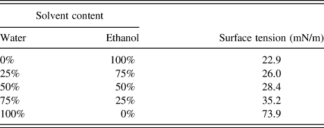
As for suspensions with the same size of particles, a higher surface tension of sol and lower evaporation rate is desired. The surface instability of the deposition from suspension 4 & 5 [as shown in Figs. 6(e) and 6(f)] was caused by the fast evaporation and low surface tension of the solvent, compared to suspension 3. The lateral flow of the solvent during evaporation can cause the surface instability. As the liquid air interface recedes into the packed particles, the capillary force withdrawals liquid from the supersaturated region. Reference Cima, Lewis and Devoe46 If considering a steady state and the balance between the evaporation and lateral flow driven by capillary pressure, the pressure distribution in liquid near a drying front can be derived. Reference Lewis44,Reference Chiu and Cima47 The characteristic length L c of liquid migration is determined by the driving force (ΔP c), evaporation rate, and viscosity of the liquid. Reference Chiu and Cima47 The magnitude of L c is the indicator of the maximum length-scale over which capillary forces dominates. When L c ≪ h, the liquid–vapor interface penetrates into the body as a planar front. When L c > h, the interface penetrates into the layer as an irregular front. The liquid is removed from the particle body homogeneously if capillary force draws liquid to the surface. When L c ≪ h, the sharp stress gradient results in film cracking, which should be avoided. The L c can be increased by decreasing evaporation rate and/or increasing surface tension. In our study, we observed significant liquid migration caused by lateral flow, when we used a low surface tension liquid with high evaporation rate. In this case, cracking is formed during the mass transport of fluid. To eliminate the surface instability, a solvent mixture containing ethanol and water is desired. Surface tension of liquids containing ethanol and water with different ratios is summarized in Table II. Adding water to ethanol can increase the surface tension of the ethanol/water solution. Also the evaporation rate of the ethanol/water solution generally depends on the ratio between water and ethanol. Reference Sefiane, Tadrist and Douglas48 It is reasonable to assume that adding water can result in a much slower evaporation rate when the solvent evaporated and liquid–air interface receded into the particle networks.
Surface tension of the mullite sol–solvent liquid mixture [mullite concentration (yield): 2 wt%]; surface tension of pure ethanol and water at room temperature: 22.4 and 72.9 mN/m.

B. Cracking upon drying and heating
When lateral migration of fluid is insignificant (L c > h), the liquid pressure distribution can be assumed to be approximately uniform in the saturated region. In this situation, granular ceramic films can still crack during drying when the thickness is greater than the critical thickness t c, above which cracking substantially occurs. Figure 7 shows that when suspension 3 was used for film deposition, cracks occurred when the thickness excessed the critical thickness. The critical thickness of films obtained from suspension 3 is smaller than those from suspension 1 & 2. However, it is greater than those from suspension 4 & 5.
The cracking mechanism of thin elastic layer bonded to rigid substrate has been derived based on Griffith’s criterion for equilibrium crack propagation. Reference Beuth49,Reference Xia and Hutchinson50 The critical thickness value is a function of the magnitude of the biaxial stress and the fracture resistance of the material. Reference Xu, Mujumdar and Yu51 Thinner films are more resistant to cracking. Upon drying, capillary forces induced by the liquid–air meniscus exert compressive stress onto the gel particles, resulting in a tendency to shrink the particle-gel network. As the coatings are bonded to the substrate which resists to the tendency of shrinkage, cracks may form to release the elastic energies. Upon heating at the low temperature regime (typically <500 °C), decomposition of the sol-derived phase took place with the changing of chemical compositions, densities and mechanical properties, causing a dilatational transformation strain in the phase. The transformation strain leads to the mechanical equilibrium between the particles, sol-derived phases and the substrate. As for temperatures above 500 °C, there is no difference in chemical compositions between the particle and sol-derived phase, and it is reasonable to assume a single phase material for the coating above this temperature. At high temperature regime (typically >1000 °C), sintering effect and thermal mismatch can be significant.
In our study, we observed a greater critical thickness as the particle size increases. Meanwhile, we observed an increase in porosity and pore size of the coating network. The observation agrees with the previous studies that cracking can be inhibited with the formation of porous coatings. Reference Kozuka52 One reason is that large pore size lowers the capillary pressure during drying. Another reason is that the presence of large volume of voids increases the total volume of the coatings per weight. Effectively the volume fraction of the sol-derived phase is reduced, in which the transformation strain during sol decomposition is compensated. Reference Kozuka52 However, the increase in critical thickness was a trade-off of the coating densities and surface properties (roughness), as the pores in micrometer scale inside the coatings are difficult to eliminate. Reference Kanzaki, Tabata, Kumazawa and Ohta3 A balance between coating properties (porosities, pore size, and roughness) and thickness shall be considered.
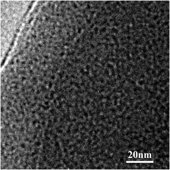
In coatings obtained from suspension 3, the capillary pressure of liquid was able to compress the solid to its maximum strain. Figure 7(b) shows that even for a cracked film, the nanoparticles are very closely packed after drying and sintering. Soft particles would result in small stress because they have small modulus. Although the mullite gel did not contain organic components after heated to 500 °C according to our previous studies, Reference Chen, Zhang, Tsai, Kornev, Luzinov, Fang and Peng35 we found that the gel particles that heat-treated at 500 °C, were highly porous, with the pore sizes of a couple of nanometers (Fig. 8). The porous microstructure can significantly reduce the shear modulus of the gel particles. In addition, the mullite sol in the liquid can form a soft shell on the particle surface during drying, and further reduce the modulus of the particles. We observed different microstructure for the films obtained from suspension 4 and 5. The dense compact microstructure in the film obtained from suspension 3 indicated a strain-limited scenario, Reference Tirumkudulu and Russel53,Reference Singh and Tirumkudulu54 in which high surface tension liquid compress the particles to their maximum attainable strain. Reference Tirumkudulu and Russel53,Reference Singh and Tirumkudulu54 The porous microstructure observed in the film obtained from suspensions 4 and 5, indicated the stress-limited feature, Reference Tirumkudulu and Russel53,Reference Singh and Tirumkudulu54 for which the particles were not pulled together by the capillary force. Although the coatings obtained from suspension 4 and 5 are more porous, the critical thicknesses are however limited by their nonuniform structures and local stress raisers. Traditionally, people would think that cracking could be avoided by reducing surface tension of the liquid. Our results showed the opposite trends. Adding small amount of high surface tension liquid (i.e., water) helped to eliminate cracking, since a large surface tension liquid and slow evaporation rate can pull the particles together without cracking.
TEM image of a mullite gel particle heat treated at 500 °C. The gel appears to be microporous with pore size around 2–5 nm.

C. Densification of mullite coatings by viscous flow
To achieve dense mullite film during sintering process is important. The sintering of mullite requires very high temperature. Reference Erk, Deschaseaux and Trice34 For example, pressureless sintering of bulk mullite usually requires 1650 °C. Reference Erk, Deschaseaux and Trice34 Even for mullite nanopowder of about 100 nm particle size, which was synthesized using flame spray method, full densification was achieved at 1600 °C under 90 MPa pressure. Reference Baranwal, Villar, Garcia and Laine55 In our study, we can achieve dense mullite film at a relatively low temperature. There are two reasons for the success of hybrid approach. The mullite sol acted as the binder of the particles. Different from the polymer binders, the mullite sol itself can have up to about 50 wt% of the mullite yield (TGA result in Fig. 2). This mullite yield can significantly increase the initial mullite density before sintering. In addition, the use of amorphous nanoparticles, instead of fully crystalline nanoparticles, has the advantages of high mass transport rate at high temperatures that promotes sintering. According to our XRD result, when mullite gel was heat-treated below 800 °C, it was still amorphous. Amorphous oxides can have the viscous flow as the major mass transport mechanism, instead of diffusion, at the temperature above T g and below crystallization temperature. Reference Kalogeras and Lobland56 From our DTA result, the T g was at about 950 °C, and crystallization temperature occurred at 1000 °C. Thus there was a viscous flow temperature window at ∼950–1000 °C. Our SEM micrograph showed that at 1000 °C, the film was almost dense [Fig. 6(c)]. This is the evidence that viscous flow, instead of diffusion played a dominant role during sintering. Nanopores and small cracks formed during drying or pyrolysis can be all eliminated after firing at 1200 °C [as shown in Fig. 6(b)], which demonstrated the advantage of the hybrid coating process.
V. SUMMARY
To summarize, we studied the processing of mullite films using the gel particle/sol hybrid approach. Mullite sol and gel nanoparticles were synthesized from the same precursor. By controlling the particle size, surface tension and evaporation rate of solvent, we can obtain dense as-deposited films without surface instability. Selection of a smaller particle size helps improve the coating density and eliminate large pores, which at the same time trades off the critical thickness. Fast evaporation and small capillary force caused surface instability due to the small characteristic length of liquid migration. The capillary suction withdrawing liquid from the supersaturated region to the saturated region was governed by the capillary-driven liquid migration and evaporation process. A less volatile solvent with larger surface tension and smaller viscosity was desired to achieve small stress gradient, therefore inhibiting surface instability.
Different from the previous reported particle-sol coating approach, amorphous gel particles were selected as the solid phase. The amorphous gel particles have the advantage of small shear modulus. The soft gel particles as well as large surface tension liquid resulted in high packing density. Additionally, the amorphous gel particles underwent glass-transition before crystallization during the heat treatment, which facilitates the viscous flow densification process. Dense and crack-free mullite films with 500–600 nm thickness can be obtained after firing at 1000–1200 °C.