Introduction
To meet the huge growth in the data rate of wireless devices and to ensure the mobile connectivity to a huge number of devices, the technology is being shifted towards the fifth generation (5G) which is expected to be commercially out by 2020. The main motive of 5G technologies is to provide around 10 Gbps data rate for the user which is about ten folds the data rate of 4G-LTE. It aims at providing this data rate along with low latencies and good reliability. It is expected that 5G is surely going to make an effective impact on a number of applications in various fields that will improve the lifestyle of the majority of population [Reference Sarkar and Srivastava1].
While dealing with a number of frequencies, it is assumed that the Radio Access Networks (RANs) for 5G are going to support several 5G bands simultaneously [Reference Asif, Anbiyaei, Ford, OFarrell and Langley2]. In order to study the demand for the spectrum required for international mobile telecommunication (IMT), the ITU-R has fixed up some criteria. In recent times ITU-R is almost done with the study for this demand fulfilling the criteria towards 2020 [Reference Sarkar and Srivastava1]. The proposed antenna covers the 5G frequency bands that include ITU n77 (3.3–4.2) GHz and n79 (4.4–5) GHz. It has been immensely studied that the frequencies in the lower range are going to provide much good coverage for recent wireless communications. For 5G communication it is not only about getting high data rates but it should also ensure wider coverage area with outside to inside network coverage by using the spectrum bands under 6 GHz [Reference Wang, Li, Ding, Miao, Li and Wang3].
There has been an initiative of deploying 5G commercially in the frequency range of sub-6 GHz. The ITU has declared sub-6 GHz and millimeter wave spectrum for 5G. An ever-growing desire for transmission at high data rates with low power levels and low costs motivated the engineers to make the effective and efficient use of 5G technology by designing the antennas that support almost all such desirable features [Reference Sarkar and Srivastava1]. A number of sub-6 GHz antenna designs reported in the literature wherein good performances have been shown, largely include the printed antenna technology. The technologies have produced the miniaturized antennas thereby retaining the good efficiency. A large class of these antennas comprises printed micro-strip slot antennas [Reference Dang, Lei, Xie, Ning and Fan4]. The slot antennas are being employed for a wide range of applications that mainly include WiMAX, WLAN, Bluetooth, 4G LTE, etc. In spite of already reported applications, slot antennas are broadly used for wireless 5G applications that mainly include mobile terminal devices in the recent scenario. The proposed rectangular slot antenna has been mainly designed for sub-6 GHz 5G applications for mobile handheld devices. A number of techniques for slot antenna design is reported in literature comprising cross-shaped slot coupler antenna [Reference Zhou, Wei, Tang and Yin5], circular patch antenna with asymmetrical open slots [Reference Liu, Li, Yang and Liu6], C-shaped coupled fed antenna with L-shaped monopole slot having orthogonal polarization [Reference Li, Ban, Xu, Wu, Sim, Kang and Yu7], octagonal shaped slot antenna with U-shaped strips for UWB applications [Reference Bod, Hassani and Samadi Taheri8], a monopole radiator with square slot having L-shaped strips [Reference Hu, Yin, Fei and Yang9], a transformer triple band slot antenna [Reference Dang, Lei, Xie, Ning and Fan4], a wideband slot antenna with fictitious resonances [Reference Behdad and Sarabandi10], a hexagonal shaped slot antenna with U-shaped slot and two split rings [Reference Dong, Liao, Xu, Cai and Liu11], inverted F-antennas for dual mode operation [Reference Hu, Liu, Gao, Wen, Qian, Feng, Xu, Fei and Liu12], antenna with defected ground having F-shaped slots [Reference Gautam, Kumar, Kanaujia and Rambabu13], an elliptical patch antenna with elliptical slot and dipole fed [Reference Huang, Lin, Huang, Zhang, Zhang and Wu14], an antenna with a radiating element comprising of CSRR slots and fed by a meandered CPW [Reference Pandeeswari15], a fractured-slotted ground plane with F-shaped structures [Reference Alsaif, Usman, Chugtai and Nasir16], F-shaped slotted MIMO antenna with users hand effect [Reference Khan, Abdullah Al-Hadi, Soh, Ali, Al-Bawri and Owais17], two monopole antennas having two rectangular etched slots and a T-shaped stub [Reference Xiong and Gao18], U-shaped slot antennas with wide band applications [Reference Mok, Wong, Luk and Lee19, Reference Lee, Yang and Kishk20].
However, the printed slot antenna designs with relatively high gain, higher efficiencies, and compact size remain a concern. For the sub-6 GHz band of 5G applications, the literature reports certain disadvantages of the slot antennas that include the larger slot dimensions, low impedance bandwidth, small gain, low efficiencies, etc. Since the space is limited in the 5G handheld devices, it becomes an essential need that the antenna is placed with the dielectric back cover of the mobile device. For this reason, low profile antennas are required for 5G applications. It implies that the total antenna thickness should be around 1 mm i.e. about 0.01 λ 0 at 3.3 GHz [Reference Barani, Wong, Zhang and Li21]. The proposed structure has been developed in accordance with 5G applications where the effect of the dielectric back cover and human tissues have been studied which are considered the most important with respect to mobile terminal applications. Another important aspect of 5G smartphone application is the measurement of SAR (specific absorption rate) values with respect to the head-hand model.
Major contributions of this work
In this paper, a rectangular slot antenna is proposed with a radiating slot, loaded with an inverted U-shaped stub with a strip connected to its upper edge designed on the top side of the substrate and a folded T-shaped micro-strip feed line on its bottom side. The proposed antenna is designed for ITU sub-6 GHz 5G applications with the realized peak gain of around 7.17 dBi. The antenna is optimized with targeted size to achieve the compact slot dimensions of 0.3 λ0 × 0.17 λ0 and the overall physical size of 0.39 λ0 × 0.34 λ0. The proposed slot antenna is of low profile around 0.009 λ0 at 3.3 GHz. The printed slot antennas are proving to be good candidates for the design of multi-band antennas owing to their benefits of easy fabrication, cost-effectiveness, and low profile. In the proposed antenna rectangular slot acts as a radiator for the generated 3.2–3.56 GHz frequency band and an inverted U-stub for 4.2–5GHz generated band. The resonant frequencies and gain can be controlled by tuning the stub parameters. The fabricated prototype seems to exhibit stable patterns, realizable gain at the respective generated frequency bands. The antenna performance is being assessed by simulating it with the back cover also in the presence of lossy human tissues. The back cover has shown a prominent effect on the S-parameters whereas the human head-hand effect has shown the effects on the radiation patterns as well as the efficiency of the proposed antenna.
The paper is organized as follows. Section “Proposed design and simulation framework” describes the details of the proposed slot-antenna which is designed and simulated in the computer simulated technology (CST) environment. The fabrication and experimental details are given in Section “Fabrication and characterization setup”. Section “Antenna analysis” gives an insight into the analysis of antenna design wherein the parameters have been optimized in order to get the desired results. All the simulated and measured results of the design and their comparison with the literature are given in the Section “Results and discussion”.
Proposed design and simulation framework
The proposed double-band rectangular slot antenna is designed on the top and bottom sides of FR4 substrate of thickness “h” (h = 0.8 mm), dielectric constant/relative permittivity “ɛr” (ɛr = 4.3), and the loss tangent “δ” (δ = 0.025). The antenna schematic as shown in Fig. 1 comprises of a slot, rectangular in shape with the slot dimensions of Ws × Ls. The slot is cut from the metallic ground on the top side of the substrate.
Schematic of proposed slot antenna (a) top side (b) bottom side.

The given slot antenna is fed by a micro-strip line having a width “Wf” designed on the bottom side of the substrate. For a compact antenna structure, the feed line comprises two horizontal metal strips of which the uppermost one is double folded with a cut in the center. The feed line is connected to the metal strips via an impedance transformer of length “Lt” for impedance matching with 50 Ω line. The overall micro-strip feed line is of T-shaped structure with appropriately optimized dimensions. The antenna consists of a somewhat inverted U-shaped stub element with a metallic strip connected to the upper edge of the rectangular slot. The antenna slot acts as the radiator that generated the frequency band of 4.2–4.84 GHz. On loading the antenna with the stub, the frequency band of 3.2–3.56 GHz is generated. Both the generated frequency modes are viable for sub-6 GHz 5G applications.
In Table 1 all the given optimized parameters of the proposed antenna design used for the final fabrication of the prototype and subsequently been characterized for the measurement of results. The proposed antenna is designed and simulated in the CST (Computer Simulated Technology) Microwave Studio Suite. The simulation results included the −10 dB return loss parameter, radiation pattern, efficiency, and peak gain for the design having the reference impedance of 50 Ω along the feed line.
Dimensions of the proposed design in “mm”

Fabrication and characterization setup
The simulated antenna prototype is fabricated by the photo-etching process. The fabricated prototype of the antenna is shown in Figs 2(a) and 2(b). The fabricated prototype is characterized using the antenna measurement set-up comprising of VNA-E5071C Vector Network Analyzer and the test measurement horn antenna setup of the anechoic chamber. The measurement system is wholly an automated system, wherein the radiation parameters for all angles of azimuth and elevation planes are computed using Antenna Measurement Studio which is a precision antenna measurement system and data processing software.
Fabricated prototype of the design (a) bottom view (b) top view.

Antenna analysis
The resonant frequency of the slot antenna depends on the length and width of the slot as well as on the effective dielectric constant of the material. The resonant frequency is given as:
$F_t = {c \over {2( {Ws + Ls} ) \sqrt \varepsilon }} = 4\,{\rm MHz}$ (approximately), where, ɛ = ɛr + 1/2 represents dielectric constant of medium [Reference Liu, Zhu, Choi and Zhang22].
The wave propagates at approximately half the speed in a medium than in the free space that ultimately results in the decreased wavelength as depicted by ${\rm \lambda } = {\rm \;\lambda }0/\sqrt {\rm \varepsilon }$ where, λ0 is the free space wavelength [Reference Liu, Zhu, Choi and Zhang22]. The concept is used while designing the miniaturized antennas as the resonating antennas are of the size of half-wavelength. The proposed antenna design is analyzed for the following two conditions:
(a) The antenna with the slot and the feed patch.
(b) The design with the stub loaded on the slot.
The analysis of the radiating portions of the double band slot antenna in the abovementioned conditions implies that in the first condition antenna generated the frequency band of 4.2–4.84 GHz centered at 4.5 GHz. In the second condition, it generated the second frequency band of 3.2–3.56 GHz centered at 3.3 GHz. The antenna is analyzed for all the parameters including the slot dimensions, stub dimensions, and patch feed dimensions. The effect of all the parameters is summarized as:
(1) The frequency band 4.2–4.84 GHz is generated by using the parameters “W1” and “Wc” of the feed patch and length “Ls” of the slot. The effect of W 1 and Wc is shown in Fig. 3(a). Having W 1 = 26 mm, Wc = 5 mm, and Ls = 16 mm, the generated frequencies cover n77 (3.3–4.2 GHz) and n79 (4.4–5 GHz) bands.
(2) The frequency band 3.2–3.56 GHz is generated by using the parameter “Ws 1” and “Ws2” of the stub loaded in the slot as shown in Fig. 3(b). By optimizing these parameters, it is observed that for Ws1 = 25 mm and Ws 2 = 1 mm the frequency generated covers the ITU n77 (3.3–4.2 GHz) band.
(3) The impedance matching of 50 Ω is achieved by using Wf = 1.56 mm (width of feed line), Lt = 2 mm (length of the transformer). It is also observed that the lower bottom length of the ground plane has a prominent effect on the impedance matching.
(4) By using the parameter “Ls 1”, the gain of the antenna is considerably improved. The realized peak gain of the proposed antenna is improved by around 1.5 dBi by optimizing the Ls 1 to 3.5 mm.
Simulated S 11 with different values of (a) W 1, Wc (b) W s1, Ws2.

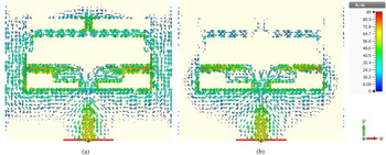
The study of the proposed design shows that the antenna with the rectangular slot and the micro-strip feeding network generated 4.2–4.84 GHz frequency band. On loading the antenna with the stub towards the upper edge of the slot, the antenna generated the second frequency band of 3.2–3.56 GHz. In order to understand the operation of the design, the surface current parameter has been extracted and shown in Fig. 4. It shows, at 4.5 GHz, the currents are flowing along the edges of the etched slot and the double-folded edge of the feed patch owing to the generation of 4.2–4.84 GHz frequency band. At 3.3 GHz, the surface currents are dense along the length of the stub which generated frequency band of 3.2–3.56 GHz. The surface currents justify both the frequency bands generated.
Simulated current distributions at (a) 3.3 GHz (b) 4.5 GHz.

Results and discussion
The characteristic study of the proposed dual-band antenna design is done using the CST studio suite. The measurement of the fabricated prototype is done using antenna measurement equipment. The S 11 parameters of the prototype are measured using VNA and the radiation pattern parameters being measured using VNA and the set-up consisting of pyramidal horn-antenna for testing in the anechoic chamber. The measurements show that antenna resonates in the frequency bands of 3.29–3.63 GHz and 4.39–5.2 GHz which are quite comparable to the simulated results of 3.2–3.56 GHz and 4.2–4.84 GHz, respectively. The simulated and measured S 11 parameters of the fabricated antenna design with stub and simulated S 11 results without stub are shown in Fig. 5. The simulated and measured results depict that the obtained −10 dB return loss (S 11 parameters) of the proposed antenna covers the sub-6 GHz frequency bands n77 (3.3–4.2 GHz), n78 (3.3–3.8 GHz), and n79 (4.4–5 GHz) that are designated for future generation 5G applications by ITU [Reference Huang, Lin, Huang, Zhang, Zhang and Wu14]. The minor differences between the simulated and measured results might be because of certain discrepancy during the fabrication process and the soldering of the connector. The differences in the measured S-parameters are subject to the setting in the anechoic chamber that might be including excess metal.
S 11 parameters (a) Simulated and Measured S 11 with stub, (b) Simulated S 11 without stub.

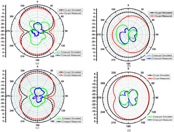
Figure 6 shows the simulated and measured radiation pattern of the fabricated design at the desired frequencies of 3.3 and 4.5 GHz. Radiation pattern comprises co-polarization as well as cross- polarization plots in both E- and H-plane. It can be deduced from the observation of the pattern that in one plane it resembles omni-directional pattern whereas in other planes it is of dumb-bell shape which agrees with the statement that rectangular slot antenna is quite similar to the “ λ/2” dipole antenna in its pattern [Reference Liu, Zhu, Choi and Zhang22]. The observed half-power beam width for the proposed antenna is around 83.4° in the E-plane and 75.3° along the H-plane field at the operating frequency of 3.3 GHz. At 4.5 GHz the HPBW in the E-plane is 75.8° while along H-plane it is around 71.2°. The results depict a wider HPBW in both planes at the respective frequencies.
Radiation patterns of the antenna prototype with co-pol and cross-pol (a) E-plane (3.3 GHz) (b) H-plane (3.3 GHz) (c) E-plane (4.5 GHz) (d) H-plane (4.5 GHz).

After measuring the radiation pattern parameters of the fabricated prototype, the antenna gain and efficiency are computed manually. At lower frequencies, there are electrically small currents due to the reduced ground plane. As a result of this, some of the antenna currents tend to flow backwards along the outer surface. This might have caused some inaccuracies in the measurement of the radiation patterns in addition with some alteration in the distribution of current along the edges of the antenna. This is the prominent reason for the reduced gain at the lower frequencies wherein the antenna is not radiating and not creating any resonant frequency.
The gain of the proposed antenna design has been measured by using the Gain Transfer Method/Gain Comparison Method as per the IEEE standard test procedure. For the gain calculation, one reference antenna is used whose gain is known and its placed on an antenna positioner in the anechoic chamber. The fabricated prototype is then aligned with the reference horn antenna at a suitable distance in the direction of maximum radiation. In our measurement purpose, we have used the VNA for gain calculation where S 21 parameter is being activated which gives the gain of the proposed antenna with respect to the reference antenna. The measurement setup which includes anechoic chamber and VNA are shown in Fig. 7. The measured results show that the realized peak gain of the proposed antenna is 7.17 dBi which is in agreement with the simulated peak gain of around 7.81 dBi as shown in Fig. 8(a). Since antenna measurement equipment is fully automated wherein first the gain is measured in addition to reflection coefficient and directivity. Finally, the efficiency of the antenna is computed. The measured results show that the fabricated prototype radiates with the total efficiency of around 79.58% which is comparable to the simulated results as shown in Fig. 8(b).
Measurement setup VNA and Anechoic Chamber.

(a) Gain of the proposed antenna. (b) Efficiency of the proposed antenna.

The proposed antenna has been analyzed for the effect of the back cover made of dielectric material with permittivity and loss tangent of 3.32 and 0.002, respectively. The schematic of the antenna with a back cover is shown in Fig. 9. The simulated S-parameters and the respective efficiency of the antenna with back cover are shown in Fig. 10. As observed from the results, there is a slight difference on comparing the antenna without and with the back cover which is mainly due to the dielectric loss due to the back-cover material.
Antenna schematic with the dielectric back cover.

Comparison of S 11 parameter and Efficiency with and without dielectric back cover.

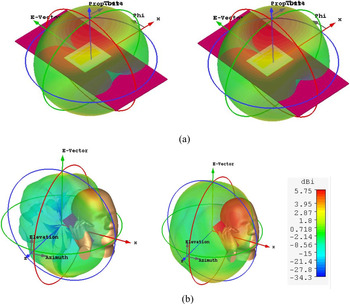
One of the most important parameters that have an impact on the radiation pattern changes in an antenna in the presence of human head-hand tissues is SAR (specific absorption rate) value. The antenna has been investigated for SAR parameter and the results show better performance in the presence of head-hand tissues. There has been a reduction in total antenna efficiency and it may be emphasized to be because of the lossy nature of human hand tissues but still it is observed to be around 60% which is very much acceptable for 5G mobile applications. The radiation patterns of the antenna seem to be very effective with good gain values however there are certain discrepancies in the characteristics but their effect is not too significant in the presented antenna design. The radiation patterns of the antenna with back cover and in the presence of human head-hand model are shown in Figs 11(a) and 11(b).
Radiation patterns of antenna (a) with back cover at 3.3 and 4.5 GHz (b) in the presence of human head-hand tissues at 3.3 and 4.5 GHz.

The antenna has been studied for SAR effect which is a function that determines the energy absorbed by the human body while the antenna is in transmitting or receiving mode. It has been a critical parameter while designing the antenna for mobile handheld devices. The proposed antenna has been simulated for SAR results and it is observed that it has an acceptable amount of SAR values almost “<1” at 3.3 and 4.5 GHz frequencies. Figure 12 shows the simulated SAR values in the vicinity of human head-hand model.
The investigated SAR values of the proposed antenna at 3.3 and 4.5 GHz.

The comparison results of the double-band slot antenna and the work done in the literature are listed in Table 2, in which the radiating portion, antenna profile, and the corresponding peak gains are compared. It is evident from the results that the proposed antenna is having a compact size in comparison with the reference antennas taking into account the size of entire antenna including the ground plane. The gain of the reference antenna [Reference Huang, Lin, Huang, Zhang, Zhang and Wu14] and [Reference Liu, Zhu, Choi and Zhang22] is better than the proposed design; however, the profile of the proposed design is low which is suitable for 5G terminal devices. The low-profile antennas are very desirable because of the limited available space in these devices. The antenna is having desirable efficiency and impedance bandwidth in comparison with the reported state-of-the-art.
Comparison table of figure of merits with state-of-the-art designs

*projection size refers to the radiating portion of the antenna.
Conclusions and future work
A planar dual-band patch slot antenna having a rectangular slot, micro-strip patch feed is presented for sub-6 GHz future generation 5G applications. The antenna has been simulated and measured in order to study its performance with respect to its parameters including −10 dB return loss (S 11 parameters), peak gain (dBi), total efficiency, and radiation characteristics. The measured results depict that the antenna performs dual-band operation with the frequency bands of 3.29–3.56 GHz and 4.39–5.2 GHz along with a peak gain of 7.17 dBi having the radiation portion of “0.3 λ0 × 0.17 λ0” and “0.009 λ0” antenna profile. The antenna analysis has shown good performance when simulated with the dielectric back cover and in the presence of the human head-hand model. The analysis has shown acceptable amount of SAR value for safe application thereby retaining better efficiency and radiation patterns. The less complicated structure with the less cost required for fabrication including all the resulting parameters may make this antenna a viable candidate for sub-6 GHz 5G applications. The analysis of different stub structures including the optimization of stub parameters in the radiating portion needs to be considered for the future work to make the antenna viable for wideband applications with improved gain. The feeding method can also be enhanced for the future scope.
Acknowledgement
The fabrication and characterization of the proposed design were done in the antenna design and microwave engineering lab in the department of electrical engineering – Indian Institute of Technology Kanpur, India.
 Insha Ishteyaq received her bachelors in Electronics and Communication Engineering in 2013 from the University of Kashmir and her masters in 2017. She is currently working toward her Ph.D. degree in the Islamic University of Science and Technology with research interests in antenna design for 5G standards. She has published a few papers in international journals and conferences. Her research interests include modern day antenna design, millimeter wave antennas, microelectronics, and related applications.
 Issmat Shah Masoodi received his bachelors in Electronics and Communication Engineering in 2013 from the University of Jammu and his masters from SMVDU Katra. He is currently working toward his Ph.D. degree in the Islamic University of Science and Technology with research interests in antenna design for 5G standards. His research interests include modern day antenna design and millimeter wave antennas for 5G applications.
 Khalid Muzaffar received his B.Tech. in Electronics and Communication and M.Tech. in Communication and IT from NIT Srinagar, India in 2004 and 2006, respectively. He has worked in Ericson India Pvt Ltd. from July 2006 to July 2007 as a field and maintenance engineer. He joined IUST Awantipora as an assistant professor in August 2007. He received his Ph.D. from CARE, IIT Delhi, India in June 2017. His research interests are in microwave antenna design and applications of thermal imaging for microwave field imaging.