Introduction
Satellite communication plays a vital role in delivering wireless communication services to live TV broadcasting, weather radar system, and internet services [Reference Maral and Bousquet1]. International Telecommunication Union (ITU) has divided the world into three regions for satellite communication. In region 3, ITU has allocated 3.7–4.2 and 7.9–8.4 GHz for downlink communication and uplink communication in fixed satellite service. Instead of using multiple antennas, satellite communication requires a single antenna with dual-band operation [Reference Peebles2, 3]. To overcome the issue, researches proposed microstrip antennas for dual-band performance [Reference Pozar and Targonski4, Reference Shafai, Chamma, Barakat, Strickland and Seguin5].
Several dual-band antennas (non-array) had been reported in the literature. For instance, in [Reference Wang and Lo6] a microstrip antenna was proposed for dual-band operation at 0.6–0.8 and 1.1–1.9 GHz. The dual-band behavior was achieved by adding a shorting pin and slots in the radiating patch. Rectangular patch antenna loaded with D-shaped complementary split-ring resonators etched in the ground plane for dual-band operation was presented in [Reference Singh, Kanaujia, Pandey, Gangwar and Kumar7]. An F-shaped patch antenna with defected ground structure (DGS) and double squared strip for tri-band operation at 4.6, 7.3, and 11.1 GHz was discussed in [Reference Mishra, Patel and Singh8]. In [Reference Mukherjee9], a circular patch on a half hemispherical dielectric resonator antenna was proposed for 4.5 and 5.3 GHz, respectively. A planar inverted F antenna for dual-band performance was proposed in [Reference Ojaroudi, Ghadimi, Ojaroudi and Ojaroudi10]. Dual-band operation was achieved by inserting S-shaped and T-shaped slots in the radiating patch and the ground plane. A slot antenna with C-shaped strip in the ground plane was proposed for dual-band operation at 1.4 and 2.4 GHz [Reference Chen, Jiao, Zhao, Zhang, Liao and Tian11]. A circular patch antenna surrounded by mushroom-shaped strips was presented in [Reference Dai, Zhou and Cui12]. Vallappil et al. [Reference Vallappil, Khawaja, Khan and Mustaqim13] proposed a Minkowski–Sierpinski-shaped antenna for dual-band operation. Peak gain at 4 and 5.9 GHz was 0.4 and 6.2 dB, respectively. A square quadrifilar helix antenna was presented in [Reference Zheng and Gao14] for dual-band behavior at 1.2 and 1.5 GHz. Spiral antenna with the frequency-selective surface (FSS) was proposed for dual-band performance at 1.8 and 3.5 GHz [Reference Chiu and Chuang15]. Asif et al. [Reference Asif, Iftikhar, Khan, Usman and Braaten16] proposed an E-shaped microstrip patch antenna for dual-band characteristics. A triangular slot antenna using substrate-integrated waveguide (SIW) for dual-band operation at 9.5 and 12 GHz was discussed in [Reference Zhang, Hong, Zhang and Wu17]. Inverted U-shaped slot antenna using SIW was proposed for dual-band performance [Reference Barik, Cheng, Dash, Pradhan and Karthikeyan18]. Peak gain at 4.2 and 7.5 GHz was 5.3 and 5.8 dB, respectively. A monopole antenna with two sleeves was introduced in [Reference Tan and Shen19] for dual-band operation. Rectangular patch antenna using multiple substrates for dual-band operation was highlighted in [Reference Wang, Liu, Zhang, Li, Chen and Shi20]. Dual-band performance was achieved by inserting multiple slots in the radiating patch which were discussed in [Reference Tiang, Islam, Misran and Mandeep21, Reference Vijayvergiya and Panigrahi22]. A planar antenna for dual-band operation using DGS and meander lines structure was proposed in [Reference Swetha and Naidu23].
Several dual-band antenna arrays had existed in the literature. A helical antenna array for dual-band operation at 1.65 and 1.75 GHz was discussed in [Reference Yu and Lim24]. A continuous transverse stub antenna array was proposed in [Reference Prakash and Srinivasan25] for tri-band operation. Peak gain at 5.1, 6.5, and 7.4 GHz was 7.5, 5.2, and 7.5 dB, respectively. A 4 × 4 electrically steerable passive array radiator was proposed for dual-band operation at wireless local area network (WLAN) and worldwide interoperability for microwave access (WiMAX) bands [Reference Yeung, Lamperez, Sarkar and Palma26]. A 4 × 4 tightly coupled dipole antenna array was presented in [Reference Yang, Qin, Liu, Yin and Guo27]. A shared aperture stacked antenna array was proposed for dual-band operation in [Reference Chen, Zhao and Yang28]. In [Reference Mao, Gao, Wang, Chu and Yang29], aperture shared microstrip antenna array for a dual-band operation was discussed. A 3 × 2 folded dipole antenna array was proposed in [Reference Wang, Zhang, Yin and Wu30] for dual-band operation in WLAN and WiMAX bands. A 7 × 7 spanner-shaped FSS was designed and placed over a slot antenna for dual-band behavior at 3.5 and 6.2 GHz [Reference Sah, Mittal and Tripathy31]. A dome-shaped antenna array was discussed in [Reference Dewan, Rahim, Malek, Ausordin, Yusuf and Azemi32] for dual-band operation at 5.8 and 7.8 GHz. A 4 × 4 H-shaped co-aperture antenna array was presented in [Reference Wu, Wang and Guo33] for dual-band performance.
The existed literature focused on multi-substrate layers and complex structure design for dual-band operation. Therefore, a wide bandwidth with high gain is an active area of research. In this endeavor, a wide band and high gain dual-band B-shaped antenna array is proposed. The simulated impedance bandwidth (reference −10 dB) is observed at 3.7–4.2 and 7.7–8.4 GHz, respectively. The proposed B-shaped antenna array is fabricated on low-cost FR4 substrate and good consent between measured results and simulated results is observed.
Antenna array design
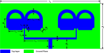
The proposed geometry of 1 × 2 B-shaped antenna array is shown in Fig. 1. The design consists of a modified rectangular patch antenna on one side of the substrate and finite ground plane on the other side. The antenna is fabricated on FR4 substrate (εr = 4.4, loss tangent 0.02, thickness 0.02λo, where λo denotes the free space wavelength at 4 GHz). The antenna array is fed by the microstrip line with 50 Ω characteristics impedance. The microstrip line terminates at T-shaped impedance-matching microstrip line [Reference Pozar34] whose values have been optimized in the simulator. The inset feed line and the round edges have been used for wide band impedance matching. Two annular-shaped strip lines have been attached on the rectangular patch to obtain dual-band and wide band characteristics. Simulations have been carried out in CST Microwave Studio 16 [35]. The dimensions of the proposed antenna array are illustrated in Table 1.
Geometry of the proposed B-shaped antenna array.

Dimensions of the proposed B-shaped antenna array

Parametric study
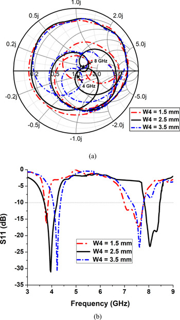
The impact of the B-shaped patch antenna has been further analyzed in this section. The length of parameter W 4 has been varied and the reflection coefficient is shown in Fig. 2. Reflection coefficient plotted on Smith chart for W 4 = 1.5, 2.5, and 3.5 mm is illustrated in Fig. 2(a) and its corresponding value in dB is represented in Fig. 2(b). Best results have been achieved at an optimum length W 4 = 2.5 mm. Further increase or decrease in parameter length results in an impedance mismatch.
Effect of change in the parameter W 4 on the reflection coefficient (a) plotted on Smith chart (b) plotted in dB.

Theory of characteristics mode (TCM) describes the current patterns and existence of the resonant modes in the B-shaped antenna. TCM can be obtained by solving the eigenvalue equation [Reference Bouezzeddine and Schroeder36, Reference Chen and Wang37]

where Jn represents characteristic currents, λ n is the eigenvalue, X and R represent the imaginary and real part of the generalized impedance.
A large quantity of modes can be calculated at any operating frequency. However, modes close to the operating frequency represent significant importance and calculated by the n modal significance (MS) equation:

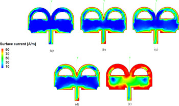
A mode resonates when its eigenvalue (λ n) is zero and MS equals to 1. TCM analysis of B-shaped unit cell has been performed in FEKO [38] and illustrated in Fig. 3. Surface current flows along the edges of the B-shaped unit cell in case of mode 1, mode 2, mode 3, and mode 4, respectively, as shown in Figs 3(a)–3(d). However, a strong surface current has been observed along the two annular-strip lines in case of mode 5 as illustrated in Fig. 3(e). The eigenvalue of the first five resonant modes of the B-shaped antenna unit cell is presented in Fig. 4. A mode resonates when its eigenvalue is zero [Reference Hassan, Zahid, Khan and Maqsood39]. For the proposed B-shaped structure, mode 1 and mode 2 resonate at 3.9 and 4.1 GHz, respectively. Mode 3, mode 4, and mode 5 resonate at 7.7, 7.8, and 8 GHz.
Surface current density of B-shaped antenna unit-cell resonance at (a) mode 1, (b) mode 2, (c) mode 3, (d) mode 4, and (e) mode 5.

Eigenvalue of the proposed B-shaped antenna unit cell.

The proposed antenna array has been fabricated and the simulated results have been compared with the measured results as shown in Fig. 5. The measured results are in good agreement with the simulated results. The measured impedance bandwidth reference −10 dB is observed at 3.84–4.16 GHz (320 MHz) and 7.78–8.38 GHz (600 MHz), respectively.
Reflection coefficient of the proposed B-shaped antenna array.

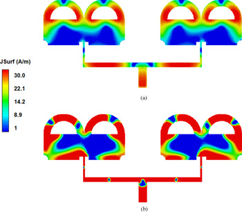
Surface current distribution of the B-shaped antenna array has been performed as shown in Fig. 6. At 4 GHz, maximum surface current flows along some portion of annular-shaped strip lines and T-shaped matching network as shown in Fig. 6(a). Strong surface current flows in the B-shaped antenna array at 8 GHz as depicted in Fig. 6(b).
Surface current distribution at (a) 4 GHz, (b) 8 GHz.

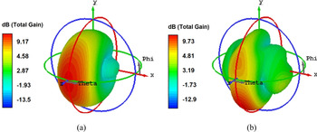
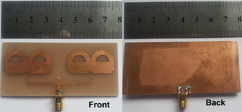
The simulated three-dimensional radiation patterns of the proposed B-shaped antenna array have been displayed in Fig. 7. The peak gain at 4 GHz is 9.17 dB as depicted in Fig. 7(a), whereas the peak gain at 8 GHz is 9.73 dB as shown in Fig. 7(b). The fabricated prototype of 1 × 2 B-shaped antenna array is shown in Fig. 8.
3D radiation pattern of the proposed B-shaped antenna array at (a) 4 GHz, (b) 8 GHz.

Prototype of fabricated 1 × 2 B-shaped antenna array.

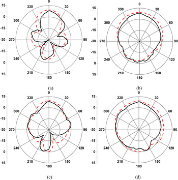
The radiation pattern of the proposed antenna array has been measured in the anechoic chamber with dimensions 9 × 4.5 × 4.9 m3. The measured radiation patterns and the simulated radiation patterns of B-shaped antenna array have been compared in Fig. 9. E-plane radiation pattern is directional whereas the H-plane radiation pattern is omni-directional. At 4 GHz, peak gain 8.3 dB occurs at 0°, whereas minimum gain −29.5 dB occurs at 240° as shown in Fig. 9(a). At 8 GHz, peak gain 9.4 dB exists at 0°, whereas minimum gain −27.1 dB exists at 160° as depicted in Fig. 9(c).
Radiation pattern of B-shape antenna array: (a) E-plane at 4 GHz, (b) H-plane at 4 GHz, (c) E-plane at 8 GHz, and (d) H-plane at 8 GHz ( simulated, ––– measured).

Peak gain and radiation efficiency of the proposed antenna array are shown in Fig. 10. Measured peak gain ranges 7.5–8.3 and 7.8–9.4 dB at 3.7–4.2 GHz and 7.7–8.4 GHz, respectively. The difference between the measured and simulated results is due to the fabrication tolerance. Measured radiation efficiency ranges 77.3–82.5% in the operating bands.
Gain and efficiency of the proposed antenna array.

The comparison of the proposed B-shaped antenna array with the existed literature has been reported in Table 2, where λo denotes free space wavelength at the lowest frequency. The table shows that the proposed antenna array is compact and possesses better gain than [Reference Yu and Lim24, Reference Prakash and Srinivasan25, Reference Dewan, Rahim, Malek, Ausordin, Yusuf and Azemi32]. Peak efficiency of the proposed antenna is comparable with [Reference Yang, Qin, Liu, Yin and Guo27]. Moreover, the impedance bandwidth (reference −10 dB) is better than [Reference Yu and Lim24, Reference Prakash and Srinivasan25, Reference Wang, Zhang, Yin and Wu30, Reference Dewan, Rahim, Malek, Ausordin, Yusuf and Azemi32], respectively.
Comparison with recently published dual-band antenna array

Conclusion
We hereby proposed a dual-band 1 × 2 B-shaped patch antenna array. The measured results show impedance bandwidths 320 and 600 MHz at 3.84–4.16 and 7.78–8.38 GHz. Measured peak gain at 4 and 8 GHz is 8.3 and 9.4 dB whereas radiation efficiency is 82.5 and 81.2%, respectively. The dimension of the proposed antenna array is 78 × 36 mm2. The results indicate the proposed antenna array is a good candidate for the satellite communication applications.
 Muhammad Mateen Hassan received his Electronics Engineering degree from the Wah Engineering College, University of Wah, Pakistan, in 2009 and the M.S. degree in Electrical Engineering from the Technische Universität Chemnitz, Germany, in 2013. Currently, he is pursuing his Ph.D. degree from the National University of Sciences and Technology, Islamabad, Pakistan. His research interests are in the field of MIMO antennas, reconfigurable antennas, micro-electro-mechanical systems (MEMS) for RF applications, and nanotechnology.
 Muzhair Hussain did his M.S. degree from the National University of Sciences and Technology (NUST), Islamabad, Pakistan, in 2019. He is currently working as a Lab Engineer in NUML, Islamabad.
 Dr. Adnan Ahmed Khan did his B.E. degree in Electrical (Telecomm) Engineering from the National University of Sciences and Technology, Pakistan. He received his Master's degree in Computer Engineering from the University of Engineering and Technology, Taxila. He received his Ph.D. degree in Computer Engineering from the Center of Advanced Studies in Engineering, affiliated with UET Taxila, Pakistan.
 Dr. Imran Rashid did his B.E. degree in Electrical (Telecomm) Engineering from the National University of Sciences and Technology, Pakistan, in 1999. He received his M.Sc. degree in Telecomm Engineering (Optical Communication) from D.T.U, Denmark in 2004 and his Ph.D. degree in Mobile Communication from the University of Manchester, UK in 2011.
 Dr. Farooq Ahmed Bhatti has got his Master degree in Solid State Physics from Punjab University Lahore, Pakistan in 1979. He did his Ph.D. degree in Radio Physics (RF Electronics) specializing in Microwave and Millimeter-wave Sources from the Department of Communication Engineering Shanghai University PR, China in 1992. He did his Post Doc in Millimeter-wave Devices from the Centre for Microwave and Millimeter-wave Circuit Design and Applications, University of Manchester, UK. He joined the National University of Sciences and Technology, Islamabad, Pakistan in 1995. Presently he is an Associate Professor at the National University of Sciences and Technology, Islamabad, Pakistan.