
Introduction
In the tooling and machining area, hard coatings are widely applied to prolong their service life and productivity. Reactive magnetron co-sputtering is one of the promising techniques with high deposition rate to develop various advance materials for hard coating surface. The binary transition-metal nitrides such as TiN, CrN and ZrN are known as the first generation of hard coating for machining tool.[ Reference Souto and Alanyali 1 – Reference Liu, Duh, Cheng and Wang 3 ] These nitrides possess higher hardness than of high speed steel and cemented carbide. However, the mechanical properties of these transition-metal nitrides are deteriorated at high temperature. To overcome these limitations, new ternary or quaternary nitride coatings such as TiAlN,[ Reference Wahlström, Hultman, Sundgren, Adibi, Petrov and Greene 4 – Reference Yang, Seo, Zhao and Zeng 6 ] CrAlN,[ Reference Fox-Rabinovich, Beake, Endrino, Veldhuis, Parkinson, Shuster and Migranov 7 – Reference Wuhrer and Yeung 9 ] ScAlN,[ Reference Moreira, Bjurstrom, Yantchev and Katardjiev 10 ] CrAlYN,[ Reference Rovere, Music, Schneider and Mayrhofer 11 ] TiAlSiN[ Reference Miletić, Panjan, Škorić, Čekada, Dražič and Kovač 12 ] and TiAlYN[ Reference Riedl, Holec, Rachbauer, Polcik, Hollerweger, Paulitsch and Paul 13 ] etc. are being developed for their outstanding oxidation resistance exceeding 1000 °C. In the last two decades, multilayers have received more attention to further improving the performance, such as the oxidation resistance at elevated temperatures as well as good wear resistance, high hardness and lower coefficient of friction for TiN/TiAlN,[ Reference Wei, Zong, Wu, Tian, Gong, Yang, Jiang and Chen 14 ] TiAlN/CrAlN[ Reference Li, Chen, Wang, Yang, Du, Li and Wu 15 ] and TiAlN/TiB2 [ Reference Sun, Yan, Zhang, Xue, Liu and Li 16 ] etc. Moreover, in multilayer made of two different materials, interfaces are postulated to act as barriers against dislocation motion. Below 10 nm, dislocation generation becomes unfavorable. It is favorable to increase the hardness and adhesion strength of the protective coating.
A TiAlN/CrAlN multilayer is believed to possess excellent properties by combining the advantages of the two components in which TiAlN film has high hardness, good wear, superior thermal stability[ Reference Wahlström, Hultman, Sundgren, Adibi, Petrov and Greene 4 – Reference Yang, Seo, Zhao and Zeng 6 ] and CrAlN film has outstanding oxidation resistance exceeding 1000 °C.[ Reference Fox-Rabinovich, Beake, Endrino, Veldhuis, Parkinson, Shuster and Migranov 7 – Reference Wuhrer and Yeung 9 ] However, insufficient efforts were made to investigate the interfacial structure of the TiAlN/CrAlN multilayers up to the present.[ Reference Yan, Li, Dong, Gao, Wang, Deng, Gu, Wan and Sun 17 , Reference Rizzo, Mirenghi, Massaro, Galietti, Capodieci, Terzi, Tapfer and Valerini 18 ] Since the thickness of nano-structured multilayers is very small (several nanometers), it is difficult to characterize surface and interface structures by scanning electron microscope (SEM), electron probe microscope analyser (EPMA) and x-ray diffraction (XRD) so far.
Reflectometry is a scattering method and is a way to get angstrom-level information on the vertical structure, such as distribution of density and thickness, through the reflectivity of the surface (or interface).[ Reference Miller, Majewski, Gog and Kuhl 19 – Reference Steitz, Gutberlet, Hauss, Liosgen, Krastev and Schemmel 21 ] X-ray reflectometry, as a powerful non-destructive technique, has been used to investigate interfaces with respect to roughness, compositional and density gradients at free surfaces and at the interfaces of multilayers.[ Reference Pardo, Megademini and Andre 22 ] For transition metal nitride multilayers, researchers obtained periodic thickness of multilayers, such as TiAlN/TiB2,[ Reference Sun, Yan, Zhang, Xue, Liu and Li 16 , Reference Liu, Kang, Wang, Li, Dong, Deng and Li 23 ] TiAlN/TiB[ Reference Rizzo, Mirenghi, Massaro, Galietti, Capodieci, Terzi, Tapfer and Valerini 18 ] and TiAlN/Al2O3.[ Reference Gao, Yan, Dong and Li 24 ] However, the characterization of the interfacial structure (i.e., interfacial roughness, interfacial diffusion and the scattering length density (SLD) along with the depth) of the ceramic multilayer is rarely performed by x-ray reflectometry so far. The possible cause is that the interpretation of the structure of heterogeneous thin films is presently a challenge due to the complexity of these films.
In this work, TiAlN, CrAlN monolayers and CrAlN/TiAlN multilayers with different repeated bilayer thickness were synthesized by magnetron sputtering. X-ray reflectometry was used to investigate the thickness, interfacial roughness and the density along with the depth for these films. The effect of the repeated bilayer thickness in multilayers on the density and interfacial roughness is discussed.
Experimental details
Film deposition
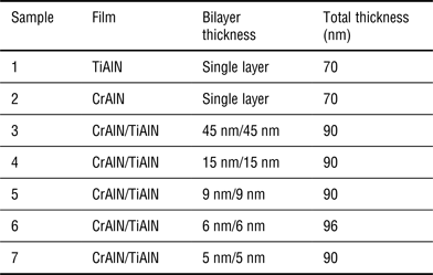
TiAlN, CrAlN films and CrAlN/TiAlN multilayers with different repeated bilayer thickness and constant modulation ratios (t CrAlN: t TiAlN = 1) were deposited on Si (100) substrate with the size of 50 × 50 mm2 and thickness of 3 mm at a fixed substrate bias of −200 V by magnetron sputtering. Surface roughness value of Si (100) does not exceed 0.8 nm. First of all, Si (100) substrates were cleaned in an ultrasonic agitator in acetone and ethanol for 10 min and dried using compressed air after each cleaning cycle. Subsequently, after the substrates were sputter-cleaned by −500 V Ar+ ion for 15 min. High purity Ti, Al (99.999%) and Cr (99.98%) targets were, respectively, connected to RF source sputter guns, which were installed with the horizontal plane. The substrates paralleled to the targets surface with a vertical distance of 60 mm to the target. The chamber was evacuated to a base pressure lower than 6.0 × 10⁻⁴ Pa. The flow rates of N2 and Ar were separately controlled by two mass flow controllers. The flow rate ratio of N2 and Ar (N2/Ar) was fixed at 3:1. The working pressure was kept at 0.5 Pa. A computer-driven shutter controlled the layer thickness of the individual layers to grow a series of CrAlN/TiAlN multilayered coatings with different repeated bilayer thickness and constant modulation ratios. The designed structure of the multilayer samples can be represented as: Si(100)/TiAlN/CrAlN, as shown in Table I.
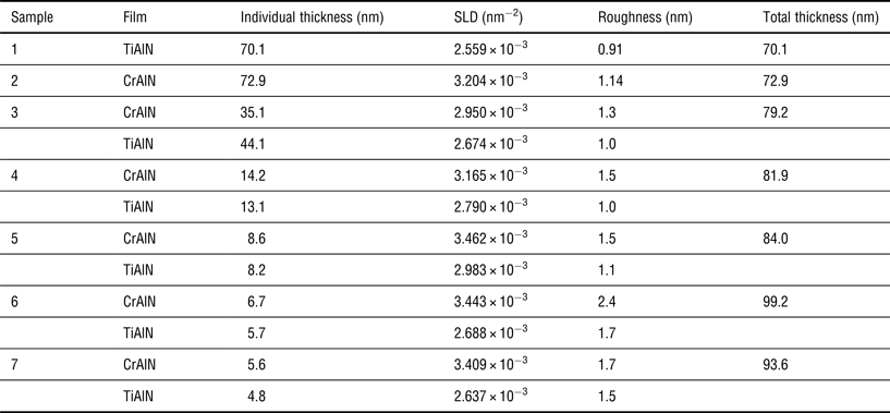
The designed samples in experiment.

The thickness of the individual layer in repeated bilayer was controlled by the open time of baffle and calculated by multiplying the deposition rate by the sputtering time. To determine the deposition rate, TiAlN and CrAlN individual layer were firstly deposited for 0.5 h, respectively and then the thickness of the individual layers was measured by a surface profiler, and the deposition rate thus can be calculated. As a result, individual layer thickness in multilayers can be calculated by multiplying the deposition rate by the sputtering time. The deposition rates of TiAlN and CrAlN are about 215 and 900 nm/h, respectively. In the present work, TiAlN and CrAlN films is referred to the full atomic composition of Ti0.5Al0.5N and Cr0.86Al0.14N, respectively.
X-ray reflectivity measurement
X-ray reflectivity (XRR) measurements were carried out using a diffractometer (Vltima IV, Rigaku Co. Ltd.) with a rotating Cu anode x-ray source (λ = 1.5406 Å), operating at 40 kV, 40 mA. The incident and reflected beams were collimated with slits of 0.05 mm in width and 2 mrh in height and the reflection intensity was measured by a scintillation counter. The specular x-ray reflectivity, R (the ratio between the reflected and the incident intensity), was measured over the Q range 0.02 Å−1 < Q < 0.14 Å−1, where Q = 4πsinθ/λ is the momentum transfer and θ is the angle of incidence/reflection. The specular reflectivity curves were recorded with a ω−2θ scan.
To determine thickness and roughness with high accuracy, it is essential to precisely align a sample position to the x-ray beam. The sample is mounted on a vertical sample stage, which is installed on a higher resolution goniometer. The 2θ angular resolution of the instrument is 0.001°. The alignment process is controlled by a computer and carried out automatically. By repeatedly adjusting z and ω (or θ) positions, an optimum position is obtained in which the sample is located at the center of the x-ray beam and only half x-ray beam is detected by the detector. Then, by setting the detector (2θ) at an appropriate position, the total external reflection adjustment starts. By further optimizing the z, ω and χ positions, maximum reflection intensity, which equals the intensity of the incident beam is achieved.
Principle and calculation procedures of x-ray reflectivity
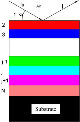
When an x-ray beam (I 0) impinges with a grazing incidence angle on N layered thin films (shown in Fig. 1), a reflectivity is defined as:
 $$\left \vert {R_{12}} \right \vert ^2 \,= I/I{}_0$$
where, I is the reflected x-ray intensity. The recursion formula is
 $$R_{\,j,j + 1} = \displaystyle{{R_{\,j + 1,j + 2} + F_{\,j,j + 1}} \over {R_{\,j + 1,j + 2}F_{\,j,j + 1} + 1}}a_j^4 $$
where,
 $$F_{\,j,j + 1} = \displaystyle{{g_j - g_{\,j + 1}} \over {g_j + g_{\,j + 1}}}\exp ( - 8\pi ^2g_jg_{\,j + 1}\sigma _{\,j + 1}^2 /\lambda ^2)$$
 $$a_j = \exp ( - i\pi g_jd_j/\lambda )$$
where λ is the wavelength, d j and a j are the j th layer thickness and surface roughness. The recursive equation was first obtained by Parratt for the x-ray reflectivity simulation.[ Reference Parratt 25 ] The roughness term was introduced in the framework of distorted wave Born approximation.[ Reference Sinha, Sirota and Garoff 26 ]
Schematic drawing of specular x-ray reflection from a multilayer.

There are four parameters for each layer, such as δ, β, thickness and roughness. The δ and β parameters are related to the refractive index n of a material
 $$n = 1 - \delta - i\beta $$
where
 $$\delta = (\lambda ^2/2\pi )r_{\rm e}\rho _{\rm e}$$
 $$\beta = \lambda \mu /4\pi $$
r e is the classical radius of an electron, ρ e is electron density, μ is linear absorption coefficient of material.
Because β is usually 1 or 2 orders of magnitude smaller than δ, it has very little effect on the fitting results. Consequently, Eq. (5) can be simplified
 $$n \approx 1 - \delta = 1 - (\lambda ^2/2\pi )r_{\rm e}\rho _{\rm e}$$
From Eq. (8) one can see that in the x-ray regime the refractive index is smaller than 1. As a consequence, the direction of incident x-ray will be changed when going from vacuum (n = 1) into the material (n < 1). From Snells law, there exists the so-called total external reflection for incident angle θ i below the critical angle θ c. The critical angle for total reflection, θ c can be expressed as
 $$\theta _{\rm c} = (2\delta )^{1/2} = \lambda \left( {\displaystyle{{r_{\rm e}\rho N_{\rm A}Z} \over {\pi M}}} \right)^{1/2}$$
where N A is the Avogadro constant, ρ is the density of the material, M is molecule weight and Z is mean atomic number. In most causes it is in the range of a tenth of a degree.
We used Parratt32 fitting software from HZB Berlin for modeling the data.[ Reference Braun 27 ] The software is based on Parratt's recursive fitting algorithm,[ Reference Parratt 25 ] which allows to calculate reflectivity data for layered model systems built up from a set of well-defined layers of homogeneous refractive index and interface roughness. The underlying model parameters are continuously varied until the experimental data and the model-based calculated data coincide within a reasonable mean square deviation, χ2.[ Reference Parratt 25 ] By independently fitting the experimental reflectivity data from XRR measurements through a theoretical model as a series of layers, SLD profiles were generated as a function of depth in the sample. Detailed structural information for the layers and the interfaces was obtained in terms of three characteristic parameters: thickness of the layers, SLD as a function of depth and interface roughness. Errors of the parameters obtained from the fits were found to be within the range of 5%–12%.
Results and discussion
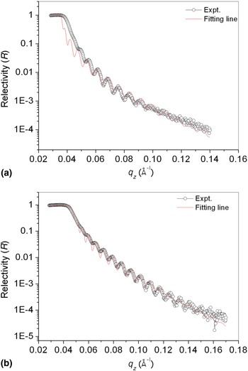
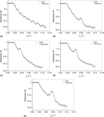
XRR pattern recorded as a function of wave vector transfer Q for the all samples are shown in Figs. 2 and 3. The open circles correspond to the experimental data and the continuous line (red) is the best fit obtained through Parratt formalism.
X-ray reflectivity curves of monolayers, (a) TiAlN, (b) CrAlN.

X-ray reflectivity curves of CrAlN/TiAlN multilayers, (a) 45 nm/45 nm, (b) 15 nm/15 nm, (c) 9 nm/9 nm, (d) 6 nm/6 nm, (e) 5 nm/5 nm.

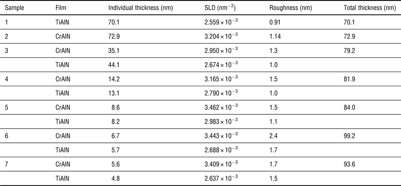
At small grazing angles, the incidence beam is totally reflected giving rise to the plateau of total reflection in each case. Over this region, usual interference fringes so called “Kiessig fringes”, due to the finite film thickness, are observed. As it is known, this interference set is originated from interference between the beams partially reflected at the air–film and film–substrate interfaces, respectively (Fig. 1). Accurately, the partial reflected beams at these two interfaces with each other depend mainly on the thickness of the different films and the angle of incidence, inducing constructive or destructive interferences. The simulation of total reflection plateau and Kiessig fringes allow to deduce the mean electron density, total thickness and interfacial roughness of each film. Those fitted parameters are summarized in Table II.
To obtain the best fit, we suppose that the structures are periodic, and thickness of the layers, scattering length densities, interface roughness are the same for all CrAlN layers in a given multilayer sample. Similar assumptions have been adopted for all TiAlN layers during the fit. The parameters extracted from the fit to XRR data, such as thickness of the layers, the scattering length densities and interface roughness for all studied samples, were summarized in Table II. Overall, the experimental data is in close agreement with the simulations, displaying the models of multilayer are reasonable in this work.
As shown in Fig. 2, the Kiessig oscillations due to total thickness of the films are clearly resolved on the reflectivity curves. The obtained thickness of TiAlN and CrAlN monolayers from fitting is 70.1 nm and 72.9 nm, respectively, which is consistent with the nominal thickness of 70 nm in Table I. The TiAlN/CrAlN multilayer's profile present not only Kiessig fringes but also another set of sinusoidal fringes for which the intense first peak (Bragg peak) is roughly located at Q z = 0.04–0.08 Å−1 for different thickness of the bilayer [Figs. 3(b)–3(e)].
Figure 3(a) shows experimental data and simulation for a 45 nm/45 nm CrAlN/TiAlN bilayer. There is no obvious Bragg peak to be observed. The reason is that the bilayer film is not periodic. However, there exist clear Bragg peaks on reflectivity curves of other four multilayers, as shown in Figs. 3(b)–3(e), and that Bragg peak becomes sharp with the decrease of the thickness of the repeated bilayers. This indicates that these multilayers are periodic (also called superlattice film), and that interface quality of the repeated bilayer improves as the thickness of the repeated bilayers decreases. It is expected to improve the mechanical properties, such as hardness, elastic modulus and ware resistance, for multilayers. Many researches showed that the hardness of multilayers increased with decrease of the thickness of the repeated bilayers, and reaches a maximum in the range of 2–10 nm for CrN/TiN,[ Reference Barshilia, Jain and Rajam 28 ] TiN/NbN,[ Reference Chu, Wong, Sproul, Rohde and Barnett 29 ] TiAlN/CrAlN[ Reference Li, Chen, Wang, Yang, Du, Li and Wu 15 ] and TiN/AlN.[ Reference Yao, Su and Kao 30 ] It can be explained by the blocking of dislocation motion at the layer interfaces due to differences in the shear moduli of the individual layer materials and by coherency strain causing periodical stress-strain fields in the case of lattice-mismatched multilayer films.[ Reference Koehler 31 ] The high interface density contributes to impeding dislocation motion and dislocation glide across the layer interfaces, which would require a critical yield stress being related to the difference in the elastic shear moduli of the individual layer materials. Moreover, Rizzo[ Reference Rizzo, Mirenghi, Massaro, Galietti, Capodieci, Terzi, Tapfer and Valerini 18 ] reported that TiAlN/AlN mutilayer presented a better wear resistance than the single films, which can be associated to the presence of many interfaces in multilayers. Each interface becomes an obstacle to the crack propagation.
From Tables I and II, the average deviation between the nominal thickness and fitted thickness for individual films in repeated bilayer and total thickness of the multilayers decreases as the thickness of the repeated bilayer in mutilayers decreases. It is indicated that x-ray reflectometry is sensitive to the films with thickness of several nanometers.
The fitted values of interface roughness for seven samples are listed in Table II. The error of the fitting of the roughness is under 1.0 Å. It is found that the interface roughness of CrAlN on TiAlN interface is larger than that of TiAlN on CrAlN interface, in the case of every sample. This phenomenon can be explained by the asymmetric interface roughness on CrAlN–TiAlN-Si interfaces for studied multilayers. Generally, surface energies of the deposited layer (γ 1) and the substrate (γ s) usually determine interface roughness. It is known that γ 1 > γ s usually causes larger interface roughness, in systems such as Pt-on-C[ Reference Ghose and Dev 32 ] and Fe-on-Si.[ Reference Gupta, Kumar and Phatak 33 ] The converse is true for C-on-Pt[ Reference Ghose and Dev 32 ] and Si-on-Fe.[ Reference Gupta, Kumar and Phatak 33 ] Moreover, it can be also seen in Table II that the interface roughness increases as the thickness of the repeated bilayer in mutilayers decreases.
Fitted parameters of films from x-ray reflectometry.
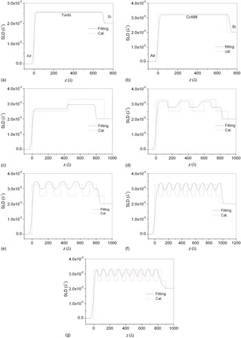
The reflectivity profiles are fitted with a model of depth-dependent SLD, from which the composition and density gradient in a layered structure can be extracted. The SLD profiles of the seven films extracted from the XRR data fit are shown in Fig. 4 as a solid line. It is found that the SLD values corresponding to TiAlN and CrAlN [Figs. 4(a) and 4(b)] are constant in the range of film thickness, indicating monolayer. Figure 4(c) shows clearly bilayer structure. Figures 4(d)–4(g) show typically periodic structure in the z-direction, indicating superlattice films. Roughness at the interfaces causes broadening of the interface layers. The SLD on the interfaces (Si/TiAlN, CrAlN/TiAlN and CrAlN/air) is dependent on the thickness of interfaces. The fitting values of SLD of the films are listed in Table II, which are relevant to the densities of films.
The x-ray reflectometry SLD depth profiles of (a) TiAlN monolayer, (b) CrAlN monolayer, (c) 45 nm/45 nm, (d) 15 nm/15 nm, (e) 9 nm/9 nm, (f) 6 nm/6 nm, (g) 5 nm/5 nm. The solid line denotes the fitting values and the dashed line denotes the calculated values from Eq. (10).

Moreover, we also theoretically calculated the scattering length densities for these films. The electron SLD associated with chemical composition of a system with more than one element can be written as,[ Reference Singh, Basu, Gupta, Majkrzak and Kienzle 34 ]
 $${\rm SLD} = r_{\rm e}\sum\limits_i {N_i(z)(Z_i + f_i^{\prime} )} $$
where Z i and f i ′ are the charge number and real anomalous dispersion factor, respectively, of the ith element, r e (=2.818 fm) is the classical electron radius and N i are the corresponding depth-dependent number densities per unit volume of the components. The calculated results are shown in Fig. 4 as a dotted line. It is found that the calculated values of SLD agree very well with the fitted values for TiAlN and CrAlN monolayers, as shown in Fig. 4(a) and (b). The calculated values of SLD, to a certain extent, deviate from the fitted values for 45 nm/45 nm, 15 nm/15 nm, 9 nm/9 nm, 6 nm/6 nm, 5 nm/5 nm samples. It is worth to note that this deviation is beyond the computated error range in the model. It is concluded that there exists the diffusion on the interfaces between CrAlN and TiAlN, which causes change of the SLD of the single films. The difference of SLD between the experimental values and theoretical values decreases with the increase of the thickness of the repeated bilayer in multilayers. This indicates that the chemical composition of films measured by x-ray reflectometry is more accurate for thicker films. This conclusion needs to be validated by more experimental data in the future. At present, there are few reports about the study of x-ray reflectometry on nano-ceramic coatings.
Conclusion
In the present work nanostructured TiAlN, CrAlN films and CrAlN/TiAlN multilayers with different repeated bilayer thickness were fabricated using reactive magnetron sputtering. X-ray reflectometry method was used to analyze interface structure of multilayers with different number of the repeated bilayers. The parameters such as the average individual thicknesses, the scattering length densities and interface roughness for all studied samples, were obtained from the fit to experimental data. The results show that the agreement between experimental and calculated reflectivity is excellent in all cases. The individual thickness in the repeated bilayers is close to the nominal thickness and the thickness of films is more accurate for thicker films. The interface roughness increases as the thickness of the repeated bilayer in mutilayers decreases. The asymmetric interface roughness on CrAlN–TiAlN-Si interfaces causes the interface roughness of CrAlN on TiAlN interface is larger than that of TiAlN on CrAlN interface, in the case of every sample. The SLD profiles of the films suggest that the chemical composition is more accurate for thicker films.
Acknowledgements
The authors gratefully acknowledge Projects supported by NPL, CAEP (Key Laboratory of Neutron Physics, Chinese Academy of Engineering Physics) (2014BB05) and the Research Foundation of Education Bureau of Liaoning Province, China.