Introduction
Communication systems are required to exchange a huge amount of information every day through radio channels, wired line telephone channels, satellite channels, and fiber optic channels [Reference Proakis and Salehi1]. Huge growth rates have been observed with present wireless technology in mobile applications, on-demand bandwidth, multimedia computing, and mass media market [Reference Schiller2]. Hence, radio frequency (RF) transceiver system designs are exponentially growing day-by-day [Reference Qizheng3, Reference Seybold4]. The wireless communication technology has seen a rapid rise since the last few decades, from first-generation (1G) to fifth-generation (5G) [Reference Garg5]. The 4G has limited data rates due to the use of 0.7/0.8/0.9/1.8/1.9/2.1/2.2/2.3/2.4/2.5/3.5 GHz frequency spectrum, and has scalable bandwidth from 5 to 20 MHz only. The 4G has spectral efficiencies for uplink and downlink in the range of 6.75–15.0 bits/s/Hz. The spectrum of the 5G covers 3.3–4.2, 4.4–4.99, and 24–28, 37–40 GHz, and many more in 60 GHz frequency band, respectively. Many companies like Samsung and Xiaomi are trying to provide the 4G–5G enabled portable phones. For 5G applications, the antenna arrays are mostly preferred to achieve higher gains and directed radiation patterns. For two-element array, the total electric field (Et) radiation is the sum of the individual electric fields and is given by equations (1) and (2).


where E 1 and E 2 are the electric field radiations of the elements, and β is the phase excitation difference between the two array elements.
The total field for an array can be determined by calculating the field of each element multiplied with the array factor (AF) and is given by equation (3) [Reference Gupta and Malviya6].

where k is the wave vector of the incident wave/wave number, d is the difference in path length between two elements, and θ is the angle of incidence on the array.
Transformation of electromagnetic waves with distributed antenna systems is very popular in modern wireless devices [Reference Kraus7, Reference Hu, Zhang and Luo8]. According to a survey conducted by Ericsson, by 2024, there will be over 1.5 million devices connected over the 5G networks. Technically, 5G provides data rates of 1–10 Gbps and higher for uploading and downloading to/from chipsets and circuit boards. Antenna properties are majorly dependent on the metal/material, and dimensions of the substrate [Reference Panhwar, Sulleman Memon, Saddar and Rajput9–Reference Haykins and Moher11].
Variety of bow-tie microstrip antennas is used for bandwidth enhancement and performance improvement. The change in the relative permittivity and substrate thickness can affect the properties of radiation patterns like gain and beam width etc. [Reference Awl, Abdulkarim, Deng, Bakir, Muhammadsharif, Karaaslan, Unal and Luo12]. An electromagnetic band gap, metamaterial (MTM), perfect magnetic conductors, and artificial magnetic conductors rectify/modify the permeability and permittivity (−ve to +ve) to enhance the antenna performance parameters such as radiation patterns, main lobe gains, reduction in side lobe levels (SLLs), directivity, minimization in return loss, bandwidth enhancement, and front-to-back ratio [Reference Alkurt and Karaaslan13]. The operation of wide banding at the lower frequency bands and for ultra-wide band (UWB) is most of the time done with coplanar waveguide fed techniques. While, at higher frequencies, high bandwidth is easily achievable. Modification of substrate and metal thickness has a positive impact on controlling the losses and surface waves. The organic solar cell is one of the new concepts in antenna designs and is used to have better performance parameters of the designed antennas with negligible losses [Reference Abdulkarim, Deng, Awl, Muhammadsharif, Altintas, Karaaslan and Luo14].
Latest wireless communication techniques efficiently exchange data/images/videos with growing low-/high-speed users and has longer life for systems and networks [Reference Schwartz15–Reference Zhi and Luk19]. With the advancement in technology, the base station antennas have become an important part of the wireless communication systems. The designers target power efficiency, polarization diversity and its adaptability to the surrounding while keeping the cost factors in mind for base station designs [Reference Balanis20]. The electromagnetic waves generated by the antennas require theoretical and practical concepts of basic laws of Faraday, Ampere, Lenz, Coulomb and others to design and implement practical antennas [Reference Harish and Sachidananda21, Reference Dateki, Seki and Minowa22]. It has observed that the maximum data rates for transmission are 384 kbps for 3G, 14.4 Mbps for 3.5G, 300 Mbps for long-term evolution (LTE), and 3.0 Gbps for LTE-advance [Reference Liao Samuel23]. The microwave frequencies (1–106 GHz) are suitable for communication systems, radar systems, microwave heating, medical electronics, defence sectors, and a variety of diverse applications [Reference Rao24, Reference Saunders and Zavala25]. Use of WLAN, WiMAX, UWB, multiple-input–multiple-output (MIMO) antenna systems, and modulation techniques have contributed in the access of higher data rates in indoor as well as in urban areas [Reference Agrawal and Zeng26]. The common issues coming up from these are the range problems, number of users connected to a single access point, and the distribution of access points over the infrastructure [Reference Rodriguez27].
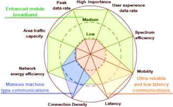
5G mobile networks are expected to provide very high connectivity speeds and their evolution is considered as the concentrator of internet services with the existing networking standards. Also, cost-per-bit reduction, energy friendliness, and easy availability of services are the most desirable traits to which the upcoming mobile generations will target [Reference Asif28, Reference Vannithamby and Talwar29]. 5G technology comprises of better cognitive radio (CR)/CDR security, low power consumption, larger data distribution, high uploading and downloading speeds and better coverage along with great energy efficiency. It provides higher data broadcasting and allows the applications to combine with artificial intelligence (AI) devices, human-to-human communications, indoor hotspot, dense urban, and rural [Reference Kachhavay and Thakare30]. Various applications of the 5G are shown in Fig. 1 graphically.
Three principle 5G usage scenarios in ITU model © [Reference Dong and Yuen31].

The 5G received power in terms of the NANT (total number of antennas), transmitted power, and free space wavelength can be written in terms of the Friis equation. The equation is based on the number of antennas in a row (AANT) and number of antennas in a column (BANT) of a phased array antenna (where NANT = AANT × BANT). The equation is given by (4). Similarly, the length and width of the 5G beamforming can also be obtained in terms of the AANT and BANT, using equations (5) and (6), respectively, [Reference Dong and Yuen31].


Furthermore, the above equations can be transformed into equation (7)

Apart from the above benefits of 5G, there are some drawbacks too. The speeds which technology is claiming might be difficult to achieve due to several factors. The devices currently in use may or may not be compatible with 5G and hence, would have to be replaced by 5G compatible ones which can be expensive. 5G devices consume huge amount of power, this will result in excess battery consumption and heat discharge. 5G waves are not capable of going through obstacles such as walls, building, trees, etc. thus would result in connectivity problems. Infrastructure development for the new network might be expensive as the existing ones will not work for 5G frequencies. Security and privacy are still a concern and is under research. Even though 5G promises to provide a larger bandwidth and larger speeds, but larger bandwidth will lead to lesser coverage. There would be a problem of overcrowding at the signals because the RFs are already occupied by other signals, such as satellite links, etc. [Reference Kolli, Mile, Shetty and Dixit32].
The above problems of the 5G can be limited using the beamforming techniques. An active phased antenna array having the beamforming capabilities are preferred to achieve higher performance of 5G millimeter-wave systems. Left-handed and right-handed elliptical polarization can be opted for the antenna designs. The electric fields for these can be expressed in equations (8) and (9) [Reference Chen, Chiu and Hsu33].


where α is the residual axis ratio.
Certain technologies such as massive MIMO, zero-latency radio access technology, device-to-device communication, etc. demand performance enhancement. Machine communication will have more authority over network connections and traffic. Network virtualization would also have an important role in 5G [Reference Pirinen34]. For outdoor applications such as in 5G cellular mobiles, cellular backhaul (which is expected to be operating on 60 GHz and E-band), and local multi-point distribution services, the frequency bands in the range 28–38 and 70–90 GHz have been explored. To solve the problem of high propagation and penetration losses, the frequencies for outdoor mm-wave applications are focused at the 28, 38, 73 and 81–86 GHz frequency range. Multiple-antenna systems and multi-directional beamformer played a crucial role in improving the signal-to-noise ratio (SNR), Ricean factor gain, and root mean square delay spread [Reference Kutty and Sen35]. The telecom operators and wireless devices’ manufacturers are investing in new technology and targeting research to have applications in the automobile industry and consumer electronics [Reference Wyglinski, Nekovee and Hou36]. The usage of 30–300 GHz frequencies in 5G will provide zero latencies (theoretically, 1 ms) and extremely higher data rates. The antennas designed on these frequencies will be smaller in size and hence, will be easier to convert them into arrays. Better connectivity and faster access led to the rapid increase in traffic for the wireless communication systems, causing interference in the network and congestion in the spectrum [Reference Charis and Showme37].
Millimeter waves vary from 1 to 10 mm and travel in a line-of-sight path and have very less diffraction, as a result, are not able to penetrate through obstacles. Hence, they are considered for personal area networks [Reference Rao, Hussain and Barman38, Reference Oshin, Luka and Atayero39]. Moreover, with the use of appropriate beamforming technique, the interferences can be reduced and frequency reuse can be enhanced [Reference Davaslioglu and Gitlin40]. Antenna arrays and phased antenna arrays have gained popularity in commercial designs, due to their compact design and the ability to focus the radiation in the desired direction [Reference Visser41]. In order to overcome multi-path scattering, multiple antennas are used to increase the data rates and multiply the number of parallel links over the same bands [Reference Biglieri, Calderbank, Constantinides, Goldsmith, Paulraj and Poor42]. These designs are carried out on thin, planar, light-weighted, and low-cost microstrips [Reference James, Hall and Wood43, Reference Lee, Luk and Lai44].
Different components of the beamforming techniques have power dividers and couplers, and are an essential part of the modern smart antenna designs. These are discussed in detail in the following section.
Couplers and power dividers
The beamforming antenna designs have main components in terms of power dividers/couplers, Wilkinson power divider (WPD), branchline/hybrid couplers, phase shifting network, and crossover networks. In power dividers, the signal is fed from a single port and the output is divided and received from the other two ports.
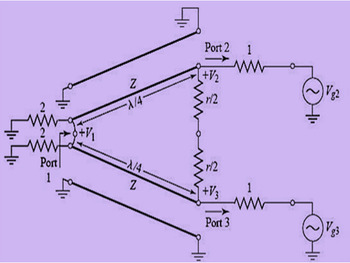
WPDs are the special kind of couplers and appear lossless when the output ports are matched, then only the reflected power from the output ports is dissipated. The WPD circuits are analyzed by reducing it into two parts, driven by symmetric and asymmetric sources at the output ports, i.e. even mode analysis, and is shown in Fig. 2. The design equations are given by (10)–(13) [Reference Pozar45].


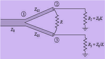
where K is the impedance value, P 2 is the desired power at port 2, P 3 is the desired power at port 3, Z 03 is the impedance for transmission line connected to port 3, and Z0 is the characteristic impedance of input line.
Wilkinson power divider © [Reference Pozar45].

Power can be divided unequally using WPD as shown in Fig. 3. If K = 1, then the design reduces to an equal power divider.
Unequal WPD © [Reference Pozar45].

WPD has the capability of achieving isolation between the output ports as well as maintaining the matching at all the ports. The unequal split WPD along with high power split ratio is gaining attention in the field of modern research [Reference Kawitkar and Ahiwale46]. WPDs have the ability of reciprocating and have equal amplitudes and phases at ports. The WPD is symmetric; the divider parameters can be derived using even mode and odd mode analysis. The even mode analysis is done by calculating the characteristic impedance, Zi and the physical lengths li of “N” transmission lines. The equivalent circuit for even mode analysis is shown in Fig. 4. The port 2 impedance is calculated as given in equation (14) [Reference Dib and Khodier47].

where $Z_{in}^0$ = 2Z 0 and Ti = tan (βli), β = 2π/λ.
Circuit for even mode analysis © [Reference Dib and Khodier47].

The values for Zi and li are calculated using the following condition given in equation (15):

where fi is the frequency for matching.
Similarly, the odd mode analysis is done by calculating the characteristic impedance. The equivalent circuit for odd mode analysis is shown in Fig. 5. The input impedance for port 2, for i = 1: N, is calculated by using equations (16) and (17).

where $Z_{in}^0 = 0$ , then $Z_{in, 2\;}^{odd} = Z_{in}^N$
 , and the value for Ri is given by:

Circuit for odd mode analysis © [Reference Dib and Khodier47].

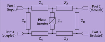
Similarly, the branchline couplers are one of the most commonly used couplers. These couplers comprise of four ports and tend to divide or combine power along with the isolations between the ports as well as 90° phase shifts. A wideband 90° hybrid coupler is shown in Fig. 6. Branchline couplers are highly preferred for applications like phase shifter, balanced amplifier, mixer, and antenna feeding network etc. [Reference Chiu48].
90° hybrid coupler © [Reference Chiu48].

The characteristic impedances ZA, ZB, and ZC are calculated using equations (18)–(20), respectively.


where k is the power division ratio.
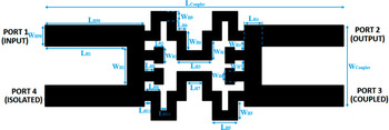
Hybrid coupler splits the input signal into two output signals with unequal amplitudes, and has four ports, out of which two are for the output ports, one is the input and the other is the isolated port. The structure can be designed using quarter-wavelength transmission lines to reduce the actual length of the design. The conventional and equivalent T-shaped transmission lines are shown in Fig. 7, and the branchline coupler is shown in Fig. 8 [Reference Moubadir, Mchbal, Touhami and Aghoutane49].
Conventional and equivalent T-shaped transmission lines © [Reference Moubadir, Mchbal, Touhami and Aghoutane49].

Branchline coupler © [Reference Moubadir, Mchbal, Touhami and Aghoutane49].

ZTLn is the characteristic impedance, and θTLn is the electrical length of the line, and can be calculated using ABCD matrix and equations (21) and (22).

and

The ABCD matrix is expressed in equation (23) for the conventional transmission lines [Reference Bajpai and Shrivastava50].

where ZTL is the characteristic impedance of the line.
Similarly, a three-port hybrid coupler can also be designed, that comprises of the phase shifter and balanced power divider. By incorporating different phase shifters, several types of hybrid couplers can be formed. For any power divider having matched ports, the input matching is necessary. Equations (24) and (25) represent the condition that needs to be satisfied for input-matching. The hybrid coupler is shown in Fig. 9 [Reference Sun, Chen, Han and Lu51].


where Zie and Zio are the line impedances, θ is the electrical length, and i = 1, 2 is used for the impedance matching.
Configuration of hybrid coupler circuit © [Reference Sun, Chen, Han and Lu51].

While assuming Z 0 and θ are known, Z 1e and Z 2e are calculated using equations (26) and (27).


A 180° hybrid coupler is able to produce the sum and difference for two input ports at two isolated ports, i.e. these couplers can create 180° phase shift between the signals at output ports. Such couplers are used for bandwidth enhancement, size reduction using shunt open stubs, arbitrary power division, and many more. A standard T-matrix of four-port network is used to analyze the coupler theoretically [Reference Moghaddasi and Wu52].
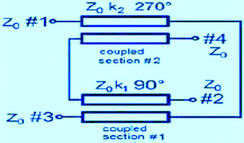
A broadband directional coupler can be designed comprising of two sections at 90 and 270°. These couplers have larger bandwidth and better frequency response, quite similar to the response of the three-port device. A broadband coupler is shown in Fig. 10. The self-impedances for the coupled conductors are calculated using equation (28).

where La,b and Ca,b are the self-inductance and self-capacitance per unit length of lines a and b, respectively, [Reference Wincza and Gruszczynski53].
Schematic diagram of broadband coupler © [Reference Wincza and Gruszczynski53].

The above discussed WPD, branchline coupler, hybrid coupler, and broadband coupler are compared in Table 1 with their applications, advantages, and disadvantages.
Comparison of different power dividers used in beamforming antennas

Beamforming consists of all the above-discussed components in most of the designs in original and modified forms. It is the technique of processing/focusing the signal beam with the help of an array at the transmitters and receivers to control the direction of the main lobe of the radiation pattern to minimize interferences. By the use of phased arrays, the phases of the signals in a particular direction are added up and the lobes present in the undesirable direction of the radiation patterns are nullified. The following section describes the beamforming and different techniques of it.
Beamforming
Beamforming is the technique of guiding the main beam of the antenna towards the desired direction and nullifying the undesired ones at the transmitter and receiver in order to achieve spatial selectivity. It can be implemented at various practical scenarios such as in radar, seismology, biomedical, sonar, etc. where there is the need for focusing the beam directions at the specified target [Reference Bhat and Dogra54]. An investigation on the beamforming systems under strict power constraints used a cyclic algorithm for MIMO system, which had low computational complexity and had better performances than the heuristic approach. Another scalar quantization technique was used for the larger number of feedback bits and vector quantization approach for the smaller number of feedback bits [Reference Zheng, Xie, Li and Stoica55].
The key factors which help us to determine whether to use spatial multiplexing or beamforming, i.e. operating SNR and bandwidth, are provided to the users, respectively. Spatial multiplexing provides beneficiary results at low operating SNR points since the transmitter splits the power and hence, weakens the streams, and causes bit error generation which can limit the overall capacity gains. Whereas, beamforming works efficiently in power-limited cases by providing better capacity by improving the SNR and allowing the usage of higher-order modulations [Reference Sun, Rappaport, Heath, Nix and Rangan56]. Various challenges are seen in beamforming network designs, i.e. reducing minimum mean square error, capacity maximization, and power constraints at various stages, complexity, antenna correlation, etc. The implementation of beamforming network in presence of single and multiple-users is also required [Reference Sharma, Senapati and Roy57]. Beamforming techniques can be briefly classified into three categories: analog, digital, and hybrid [Reference Zhao, Lukashova, Kaltenberger and Wagner58]. Different types of beamforming techniques are shown in Fig. 11 and are discussed in this section.
Classification of beamforming techniques © [Reference Ali, Ismail, Nordin and Abdulah59].

Analog beamforming
Analog beamforming is the technique where the phase is controlled by the low-phase shifters and the antennas comprise of hybrid matrices and phase shifters. Analog beamforming deals with scaling or phase-shifting the input signal using the analog methods. For the applications where the systems need to be cost-effective, analog beamforming is preferred over digital because the same system can be designed by using low-cost phase shifters [Reference Ali, Ismail, Nordin and Abdulah59].
Digital beamforming
Digital beamforming deals with controlling the phase and amplitude of the signal beam which requires RF chains and dedicated baseband. Digital beamforming is generally opted when multiple beams with high-gains are desired without the decrease in the signal-to-interference ratio. The digital beamforming can be categorized further into two categories: fixed and adaptive. In fixed digital beamforming, the weights for antenna array are predefined and are kept unchanged while the operation goes on. Whereas, in adaptive digital beamforming, the weights change and adapt according to the surrounding conditions. This property ensures that the system's capacity is enhanced because of its adaptive nature. Furthermore, these two can be divided into four categories: (1) single fixed beam/single user; (2) single fixed beam/multiple users; (3) single adaptive beam/single user; and (4) single Chebyshev dynamic beam/multi-users.
Digital beamforming is the technique in which the weights of the vectors of an input signal are added together to generate the desired output. A basic digital beamforming system would comprise of analog-to-digital converters (ADCs) and digital circuits along with basic analog building blocks. Digital beamforming techniques tend to have more errors and low SNR. In order to overcome this, zero-forcing method is used in which the elements in the antenna array direct the nulls in the direction of unwanted signals to nullify their impact. The result varies when the different number of elements, along with a different algorithm is chosen [Reference Albert and Chan60]. Even though digital beamforming has several advantages such as super-resolution, multiple-closely placed beams, flexible radar power, etc. the implementation of the technique in 5G is not preferred due to the high cost of antenna array present [Reference Steyskal61].
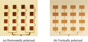
However, to maintain the cost-effectiveness and to achieve the link budget requirements in wireless communications, the digital beamforming technique is used. Two identical antenna arrays are used at the base station, which are simultaneously responsible for beamforming and are reused for reception at customer-premises-equipment. The design had 16-element patch antenna arrays, vertically and horizontally polarized, to operate in 27.5–28.35 GHz band and was fabricated on a Rogers' 4350 (ɛ r = 3.83, thickness = 0.254 mm, and loss tangent = 0.0037) substrate. The overall size of the substrate was 30 × 30 mm2. The gain was 16.02 and 15.65 dBi for structures shown in Figs 12(a) and 12(b). The propagation loss (Lfs) for the design at 28 GHz was calculated using equation (29).

where f is the frequency at which the antenna operates and d is the distance between the two antennas.
16- element array © [Reference Tariq, Psychoudakis, Eliezer and Khan62]. (a) Horizontally polarized. (b) Vertically polarized.

For calculating the received signal in low noise amplifier (LNA) and the SNR at the output, equations (30) and (31) are used, respectively. The design justifies to the cost-effectiveness requirement [Reference Tariq, Psychoudakis, Eliezer and Khan62].


where PRX and PTX are the received and transmitted signals, respectively, GRX and GTX are the gains at the receiver and transmitter ends, respectively. Also, N 0 is thermal noise, and is given in equation (32).

Hybrid beamforming
The hybrid beamforming is an efficient, cost-effective, and a reliable technique for the 5G wireless networks because of its ability to provide higher data rates with low bit error rates [Reference Islam, Jessy, Hassan, Mondal and Rahman63]. Hybrid beamforming is based on the concept that the larger number of data streams results in limiting the number of up conversions and down conversions. On the other hand, the larger number of antenna elements contribute in improving the gain and diversity of the signal. The easiest way to implement hybrid beamforming is by exploiting the channel sparsity which focuses on limiting the number of RF chains while maintaining the gain of antenna arrays. At the same time, it allocates power in the baseband and multiplexes the data. Designing array antennas for the mm-wave range is quite difficult because mm-wave signals have very high path losses as it faces difficulties while propagating, i.e. unable to go through deep surfaces, easily faded or being scattered or absorbed by the gases present in the air. To overcome this problem, a hybrid beamforming technique is used [Reference Guha, Mukherjee and Vasanthi64].
The basic advantages provided by the hybrid beamforming includes reduced hardware cost, higher energy efficiency, and enable massive MIMO. The uses of multiple antennas have resulted in reduced co-channel interference, fading, and noise. Several methods for optimizing the weights of the array were discussed in [Reference Nwalozie, Okorogu, Maduadichie and Adenola65]. In order to meet the critical requirements for the 5G networks, hybrid beamforming for mm-wave plays an important role for the 5G networking systems. Using MIMO, the spectral efficiencies can be improved by making it possible for the base station to communicate with multiple user end (UE) devices under same time–frequency–space resources and also by making multiple streams flow in between the BS and UE [Reference Ahmed, Khammari, Shahid, Musa, Kim, Poorter and Moerman66]. Beamforming effect for the bands 3.5, 10 and 20 GHz were studied and the transmitted power turned out to be 33 dBm. The comparison between hybrid beamforming and digital beamforming showed that the massive MIMO and hybrid beamforming achieved more than 20 Gbps throughput [Reference Suyama, Okuyama, Inoue and Kishiyama67]. An orthogonal frequency division multiplexing (OFDM) based hybrid beamforming technique is adapted at the transmitter side using channel stream weights (c), and at the receiver side reverse operation is performed with weights (w) on the received streams. The corresponding scheme is shown in Fig. 13 [Reference Yoon, Jeon and Lee68].
Hybrid beamforming technique © [Reference Yoon, Jeon and Lee68].

For the hybrid beamforming technique, spectral efficiency can be obtained using equation (33).

where N is the number of subcarriers, m varies from 0 to N – 1, and c and w are for gain adjustments at the transmitter and receiver, and H is the channel matrix.
The beam can be steered using the wm, which is the beam steering vector, and is given in equation (34).

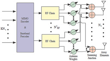
Another structure of the hybrid beamforming (transmit) using NS data streams, MIMO encoder and baseband pre-coder, RF chains (NRF), antenna weights, and receiving arrays (Nt) is given in Fig. 14. With a slide modification (reverse order), receive hybrid beamforming can be formed [Reference Kutty and Sen35].
Extended hybrid beamforming (transmit) technique © [Reference Kutty and Sen35].

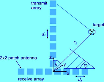
A combined technique using frequency-modulated continuous-wave for measuring range and MIMO for digital beamforming in two-dimensional (2D) is used to design a 24 GHz radar system that detects a 3D object and generates an image for the same. The digital beamforming in 2D can be obtained using the orthogonal arrangement of two antenna arrays having “M” transmitters and “N” receivers. In this case, there are eight transmitters, located at the spacing of dz = 14.2 mm, and receivers, each located at the distance of dx = 14.5 mm from each other, in the antenna array in order to achieve better resolution and medium hardware effort. The design is shown in Fig. 15.
Antenna array for 3D imaging © [Reference Harter, Schipper, Zwirello, Ziroff and Zwick69].

The T-shaped orthogonal arrangement was chosen to ensure that the transmitters and receivers provided the same polarization. Each antenna in the array had 2 × 2 patches, which provided half-power beam width (HPBW) as 42° in azimuthal plane and 50° of HPBW in the elevation plane. The system was designed on four different modules: the transmitter module, receiver module, synthesizer module, and field programmable gate array module. The switching of each transmitter was handled by an LNA at the ends of WPD. A bandwidth of around 270 MHz was obtained from the experiment and the other measurements were carried out by the corner reflector, had a cross-section of σ = 2 m2. A very small amount of angular resolution error was recorded, i.e. from −5 to +5°, for both the directions [Reference Harter, Schipper, Zwirello, Ziroff and Zwick69].
Switched beamforming
Switched beamforming is the beamforming where the user/system is able to switch between multiple beams that are generated and can choose from one of the many predefined patterns that has the main lobe in the direction of the desired signal. One of the most popular beamforming networks used is known as the Butler matrix. The matrix has been widely chosen in electronically scanned arrays as a MIMO beamforming network, because of being versatile and simpler for multiple-beam antennas. These networks are passive microwave ones, which comprises of hybrid couplers and phase shifters [Reference Fakoukakis, Kaifas, Vafiadis and Kyriacou70].
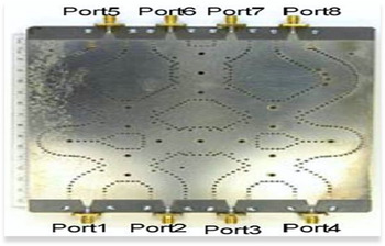
An UWB antenna was designed based on 4 × 4 Butler matrix, operating in the range from 3 to 9 GHz. The hexagonal slot geometry was used to design the microstrip patch and was fabricated on RT/Duroid 5880 substrate (ɛ r = 2.2, thickness = 0.254 mm, and loss tangent = 0.0009). The designed system achieved 6 GHz of bandwidth and delivered four orthogonal beams at −45, −15, 15, and 45° [Reference Nedil, Denidni, Djaiz and Habib71]. Another Butler matrix was designed in Ku-band using substrate integrated waveguide (SIW) technology at 12.5 GHz central frequency and had Rogers' RT/Duroid 5870 substrate (ɛ r = 2.33, thickness = 0.787 mm, and loss tangent = 0.0012). The dimension for the substrate was 144 × 146 mm2. It was observed that the isolation was better than 15 dBi and had the 3 GHz operating bandwidth. The desired phase shifts at 45° were obtained. The design is shown in Fig. 16 [Reference Djerafi, Fonseca and Wu72].
SIW 4 × 4 Butler matrix © [Reference Djerafi, Fonseca and Wu72].

The smart antennas work on two algorithms, known as the direction of arrival (DOA) and adaptive beamforming. In the case of DOA, once the signal is received by the antenna, the algorithm decides the directions based on the time delays. For any rectangular grid array, the time delay, Ʈmn, can be given in equation (35) [Reference Balanis73].

where v 0 and Δr represent the speed of the light in free space and the differential distance, respectively.
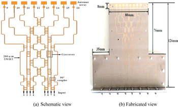
Smart antenna systems are designed in order to optimize the radiations and reception patterns generated by the combination of antenna array and signal processing units. But due to its high spatial directivity and increased complexity, it was not a suitable approach. The designers used switched beamforming approach to overcome the limitation. A patch antenna array along with an 8 × 8 Butler matrix was designed on Taconic RF35tc substrate (ɛ r = 3, thickness = 0.127 mm, and loss tangent = 0.0014) and operated on 2:1 voltage standing wave ratio (VSWR) band of 24–26 GHz frequency. The Butler matrix structure was used as a beamformer. The network yielded beams in eight different directions from the eight output ports with equal powers and progressive phases at +22.5, −22.5, 67.5, −67.5, 112.5, −112.5, 167.5, and −167.5°, respectively. The gain was better than 10 dBi in the design. The design is shown in Fig. 17 [Reference Huang, Chen and Rao74].
Switched beam antenna array with 8 × 8 Butler matrix © [Reference Huang, Chen and Rao74]. (a) Schematic view. (b) Fabricated view.

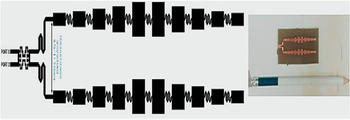
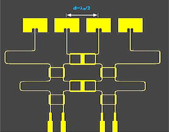
In another design, a switched beam system was designed for 23.34–28.25 GHz using hybrid couplers and antenna arrays. The antenna array had 10 × 2 patch elements with the inter-element spacing of 11.52 mm. The Rogers' RT/Duroid 622 substrate was used (ɛ r = 2.9, thickness = 0.254 mm, and loss tangent = 0.0015) along with the copper of 35 μm thickness. The maximum gain and directivity were 12.398 dBi and 13.929 dB at port 1, and 12.535 dBi and 14.068 dB at port 2. The design produced two beams with 32° beam widths. The design is shown in Fig. 18 [Reference Moubadir, Mchbal, Touhami and Aghoutane49].
Switched beam antenna array system © [Reference Moubadir, Mchbal, Touhami and Aghoutane49].

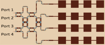
Similarly, a switched beamforming antenna system was designed for 28 GHz frequency on Roger's RO4003 substrate (ɛ r = 3, thickness = 0.127 mm, and loss tangent = 0.0013). The dimension of the patch was 3.785 × 2.823 mm2. The whole structure had a 4 × 4 matrix followed by an array of 1 × 4 patch antennas connected in such a way that inputs at the different ports of the Butler matrix led to different directions of the main beam. When the input was fed from the input ports 1 and 4, at the output, a phase difference of ±45° was observed. Similarly, when inputs were fed from the ports 2 and 3, a phase difference of ±135° was seen at the output ports. When port 1 was the input port, a beam was obtained at 15°. Similarly, from port 2 as input, a beam at −34° was obtained and beams at 33 and −15° obtained with ports 3 and 4 as input ports, respectively. Output losses due to delays were around −7.1 and −6.6 dB, when input ports were 2 and 3. When input ports were 1 and 4, the losses were −7.5 and −6.5 dB, respectively. The minimum SLL was −12.9 dB in design. The overall size of the Butler matrix was 20.3 × 13.0 mm2 and that of antenna array was 21.2 × 19.9 mm2. The design is shown in Fig. 19 [Reference Park, Kim, Sohn and Shin75].
Switched beamforming network using a 4 × 4 Butler matrix © [Reference Park, Kim, Sohn and Shin75].

Another switched beam antenna array was implemented on Rogers' RT/Duroid 5880 substrate (ɛ r = 2.2, thickness = 0.254 mm, and loss tangent = 0.0009) to resonate at 35 GHz, which offered low complexity by avoiding multiple layers. The design used 4 × 4 Butler matrix for beam steering at ±45 and ±135°. Two slits were placed at the feeder for impedance tuning. The phase differences between ports 1 and 4 were ±45 and ±135°. From ports 2 to 3, phase differences were ±15 and ±45° and the antenna gains obtained were 8 and 7 dBi, respectively. The SLL was approximately −9 dB. The design is shown in Fig. 20 [Reference Kapusuz and Oguz76].
Switched beam phased antenna array at 35 GHz © [Reference Kapusuz and Oguz76].

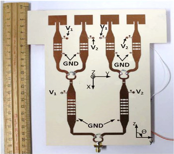
Similarly, the multi-beam antenna arrays were designed on a 4 × 8 Butler matrix to reduce the SLLs and to improve the gain. A beamforming architecture was designed with SIW multi-folded Butler matrix structure to operate at 38 GHz (37.5–38.5 GHz band). The matrix was accompanied with an 8 × 10 patched antenna array to offer beam steering in four different directions. The SIW structure provided lesser radiation losses than microstrip lines. The design was fabricated on Rogers 5880 substrate (ɛ r = 2.2, thickness = 0.254 mm, and loss tangent = 0.0009). The design opted for cross-layer structure and thus, had two substrates. An 8 × 10 patched antenna array ensured four beams for wider coverage and angular area. The beams were 12 and −12° when the ports 1 and 4 were excited. The gain at these ports was 21 and 20.9 dBi. The overall size of the substrate was 64.4 × 60 mm2, the gain in the directions −36, −12, 36, and 12° were 20.3, 21.4, 21.4, and 20.3 dBi [Reference Cao, Chin, Che, Yeng and Lee77].
Adaptive beamforming
In adaptive beamforming, the complex weights of the incoming signals are calculated and multiplied with the output elements of each array in order to optimize the results. It uses the block of data to estimate the weight vectors, known as sample matrix inversion. Another way to calculate the weight vectors is sample-by-sample, in which the weights of the vectors are updated after each sample [Reference Das78]. Adaptive beamforming is a powerful tool in suppressing the interferences and noise, as well as improving the desired signal. Smart antenna systems are the combination of signal processing and multiple-antenna elements to achieve better signal radiation and reception. Switched beam antennas and adaptive array antennas are two different categories under smart antennas [Reference Singh and Kaur79, Reference Chryssomallis80]. These systems have gained popularity in the field of wireless communication due to its structure and its ability to reduce noise, interference, and delays. These antennas further can be classified into switched beam system and adaptive arrays. A smart antenna system was designed which could perform well with adaptive beamforming. The white Gaussian noise for each element, having 10 dB SNR and three interferers at −30, −60, and 60°, respectively were achieved in design [Reference Shaukat, Hassan, Farooq, Saeed and Saleem81].
An array synthesis method, known as Tchebyscheff distribution (TD) was used to achieve the narrowest and lowest SLLs, along with two algorithms used in adaptive beamforming, i.e. least mean square (LMS) and constrained stability least mean square (CSLMS). To achieve the beam in the desired direction, θ, the array factor (AFL) is given in equations (36) and (37).

and,

where α is the progressive phase shift, and 2πd/ λ is the phase factor.
The TD was used with the LMS and CSLMS to create a beam in the desired direction as well as, in the direction of predefined null. The normalized AFs for various cases were calculated using TDLMS and TDCSLMS, by varying the SLLs in each case. When the results are compared with LMS and CSLMS, −4 to −6 dBi lower side levels were obtained [Reference Singh SN, Senapti, Deb and Roy82].
Adaptive beamforming works on two algorithms: recursive lease square (RLS) and LMS. The LMS algorithm does not work when the values of the step-size parameter are ≥0.05. Similarly, using the RLS algorithm, lower SLLs than LMS can be achieved. Also, the LMS algorithm controls the radiation pattern and has better convergence, enhanced coverage and low outage probability. The comparison of bit error rate and SNR of it in the presence and absence of beamforming verifies the implementation of CR systems' architecture [Reference Onoh, Arinze and Okafor83]. There are several algorithms to achieve adaptive beamforming: LMS, constant modulus algorithm (CMA), least square CMA (LS-CMA), and RLS. LMS algorithm was found to be the simplest and has the easiest computation methods. In this algorithm, the weight vectors are calculated using equation (38) [Reference Senapati and Roy84].

where w(n) is weight vector, x(n) is received signal from multiple elements, μ is the gain constant, and e(n) is the error between actual output and the desired signal.
Four different configurations of patch antennas were designed to operate at 28 GHz and were controlled by switches. The design was fabricated on a Rogers' 5880 substrate (ɛ r = 2.2, thickness = 0.254 mm, and loss tangent = 0.0009). The beams for different configurations have +15 and −15° beam widths, and have gains in the range of 9.54–10.9 dBi respectively [Reference Yu and Kamarudin85]. An eight-element antenna array used the RLS, LMS, and optimized LMS algorithms. The RLS has the best beamforming capability and had better performance in nullifying interferences at 40, 60, and 90°, respectively [Reference Ali, Ali, Rehman, Khan and Malik86]. The leaky least mean square (LLMS) algorithm was used to overcome the problem of slow convergence speed in LMS. The mathematical representation for updating weight in LLMS algorithm for nth iteration is given in equation (39). A 12-element array with 0.5λ spacing was used with 20 dB SNR. The LLMS algorithm generated beam at 20° for μ = 0.02. Also in the presence of multiple interferences, the null deviation up to 15% was generated [Reference Sharma, Senapati and Roy57].

where μ is the step-size, e(n) is error signal, w(n) is the filter coefficient vector, and x(n) is the received signal.
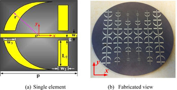
Similarly, an FSS-based circular polarizer antenna with beamforming feature was designed for 7 GHz (6–8 GHz band) on the substrate Rogers (ɛ r = 2.65, thickness = 1 mm, and loss tangent = 0.003). The FSS structure was anchor-shaped with two layers separated by 12 mm. It was observed that the beam was wider (51.33°) as compared to the non-FSS structured antenna (37°). The gain for FSS-structure was 12.88 dBi and achieved 94.89% efficiency. The overall FSS structure was implemented on 120 mm circular area. The design is shown in Fig. 21 [Reference Yin, Wan, Ren and Cui87].
Circular polarizer © [Reference Yin, Wan, Ren and Cui87]. (a) Single element. (b) Fabricated view.

Other beamforming techniques
In addition to the above beamforming techniques, there are certain other available techniques. An optimum transmit beamforming is a powerful technique in terms of increasing system capacity, helps in reduction of the interference between the waves on a multipath channel, and improves the throughput [Reference Bouhlel, Guillet, Zein and Zaharia88]. Apart from optimum transmit beamforming there are distributed and collaborative beamforming and has its applications in the 3D beamforming wireless networks [Reference Jayprakasam, Rahim and Leow89]. Another approach for beamforming is known as unitary multi-beam transformation. The technique is most efficient and fruitful in the cases when the system requires highly directional signal beams with the least SLLs [Reference Lynch90, Reference Adel, Souad, Alaqeeli and Hamid91]. For better performances, blind source separation and beamforming can be combined using two different mixtures [Reference Johnson and Aishwarya92].
Despite the use of different beamforming techniques and applied algorithms, obtaining faster convergence is still a task to do. Thus, the idea of genetic algorithm based on Charles Darwin's theory of “survival of the fittest” is used to update the array excitation coefficients. With this, the SLLs are drastically reduced and the array angle direction can be moved to the desired ones [Reference Ares-Pena, Gonzalez, Villanueva-Lopez and Rengarajan93].
Massive MIMO and mutual coupling
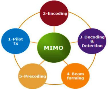
The current standards in long term evolution permits up to eight antennas for the transmission point, but for 5G networks, eight antennas per point is not enough. Hence, the concept of massive MIMO came into the picture. Massive MIMO supports more than eight antennas at each transmission point and focuses on the higher-order multi-user MIMO (MU-MIMO). Single user MIMO (SU-MIMO) deals with sending multiple data streams to a single user and involves spatial multiplexing and multipath scattering. In MU-MIMO, switched beam concept is considered in order to choose the best beam for the end-user and also, it reduces the cross-talk possibility via the side lobes of the beam [Reference Vook, Ghosh and Thomas94]. Massive MIMO has more than or equal to hundreds of base stations that serve more than or equal to tens of UE equipment. Time-division duplex is adapted in the massive MIMO instead of frequency division duplex that minimizes the signal overhead and helps acquiring channel state information (CSI) [Reference Sheikh, Joyatri Bora and Hussain95]. Massive MIMO systems have the tendency to improve the network capacity by reducing the interferences and steers the signals in the desired direction. They are capable of improving the efficiencies and throughput for the system. The propagation medium hardly affects the massive MIMO systems. Massive MIMO uses linear pre-coders to reduce the interference in the signals and enables transmission of multiple streams. Massive MIMO system has the following components, as shown in Fig. 22 [Reference Hassan and Fernando96].
Massive MIMO components © [Reference Hassan and Fernando96].

The capacity of the massive MIMO can be obtained as per the discussions given below. As per Shannon's capacity theorem for the single-input–single-output antenna (SISO) system, capacity (bits/s/Hz) is given by equation (40):

For SU-MIMO, with the independent and identically distributed Gaussian signals, the capacity (bits/s/Hz) is given by equation (41):

where B is the bandwidth, S is the signal power, N is the noise power, I is the identity covariance matrix, and H is the CSI of m × n antenna system.
For MU-MIMO, capacity (bits/s/Hz) can be given by equation (42):

where P is the power allocation for maximization of the transmission rate.
On the basis of the SISO capacity, SU-MIMO capacity, and MU-MIMO capacity, the massive MIMO capacity (bits/s/Hz) can be obtained. When the receiving antennas tend to infinity, the capacity of massive MIMO is obtained by equation (43) [Reference Sherif A, Huq, Dai and Jonathan97]:

where n is the number of transmitting antennas and m is the number of receiving antennas.
Massive MIMO is capable to accommodate the increasing users of the mobile devices and for faster responses, due to its capacity enhancement techniques. Therefore, massive MIMO can be the main ingredient in technologies such as machine-to-machine, internet of things, vertical virtual sectorization, etc. Large antenna arrays are used in the beamforming in massive MIMO to reduce path losses. Due to its compact architecture and larger mm-wave antenna array, hybrid beamforming is being considered in the network systems. In massive MIMO, the number of UE antenna elements and the number of base station elements reaches hundreds. Hence, it allows more transmission of data and even simplifies the signal processing [Reference Guha, Mukherjee and Vasanthi64]. When multi-antenna UEs in massive MIMO systems came to the picture, the number of base antennas are reduced. As a result, the signal processing complexity and the cost are reduced. But, a new problem of inter-cell interference came into the picture. To overcome this, the user equipment beamforming technique is used. The Rician fading model has low computational costs and it requires no additional channel information and a semi-definite method can be used for the calculation of beamforming vector [Reference Kammara and Shanmuganantham98]. With increased research studies in the communication field, relay networks emerged as the most reliable and having wide cell coverage while achieving high gains. These networks comprised of amplify-and-forward, and decode-and-forward protocols, half-/full-duplex communications and are able to deal with power constraints [Reference Kanatas, Vouyioukas, Zheng and Clavier99].
MIMO antennas have multiple benefits in the wireless communication system, but the problem of mutual coupling is major due to the radiators' close proximity [Reference Malviya, Panigrahi and Kartikeyan100]. Maintaining the isolation between the ports in any MIMO antenna has turned out to be the most crucial phase while designing. There are several techniques used to avoid the mutual coupling in the MIMO antennas, for example parasitic element, coupling element, decoupling element, slotted meander line resonator, etc. [Reference Malviya, Panigrahi and Kartikeyan101]. A G-shaped MIMO antenna was used with polarization diversity and partially stepped ground to overcome the effect of mutual coupling [Reference Malviya, Malik, Panigrahi and Kartikeyan102]. A T-shaped isolator was introduced in order to limit the mutual coupling effects and was fabricated on FR-4 (ɛ r = 4.4, thickness = 1.524 mm, and loss tangent = 0.025) [Reference Malviya, Panigrahi and Kartikeyan103]. In order to get the wide-band, a meander line MIMO antenna having hook-shaped elements was fabricated on FR-4 (ɛ r = 4.4, thickness = 1.524 mm, and loss tangent = 0.025). The isolation between the ports was more than 12 dB, due to the placement of elements [Reference Malviya, Gehlod and Shakya104]. Similarly, a pentagonal-shaped antenna element with T-shaped isolator was designed to provide more than 12 dB isolation at the ports [Reference Malviya, Kartikeyan and Panigrahi105].
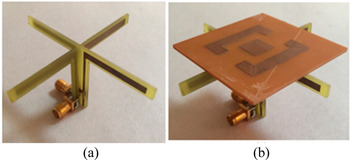
Reducing the effect of mutual coupling is MIMO antenna is a major goal. An artificial neural network was used to reduce mutual coupling. A resonator was designed for minimizing the transmission values and was added to the cross dipole antenna, as shown in Fig. 23. Each arm of the cross dipole antenna was 30.75 mm long and operated at 2.40 GHz (2.2–2.7 GHz band) on FR-4. With and without the resonator, the mutual couplings were 25.3 and 19.7 dB [Reference Ozdemir, Akgol, Alkurt, Karaaslan, Abdulkarim and Deng106].
(a) Cross dipole. (b) Cross dipole with resonator © [Reference Ozdemir, Akgol, Alkurt, Karaaslan, Abdulkarim and Deng106].

MIMO antenna with compact size radiators along with the partially extended ground structure and partial ground was designed on FR-4 substrate (ɛ r = 4.4, thickness = 1.524 mm, loss tangent = 0.025) to provide more than 12.5 dB of isolation at the ports [Reference Malviya, Kartikeyan and Panigrahi107]. In order to overcome mutual coupling, a 2 × 2 MIMO antenna with circular polarization and ground split was fabricated on FR-4 substrate (ɛ r = 4.4, thickness = 1.524 mm, and loss tangent = 0.025). To reduce the coupling between the elements in the arms of a feeding network, a slot was introduced above the feed line. The envelope correlation coefficient in the whole band was around 0.15 and had more than 33 dB isolation at the ports [Reference Malviya, Panigrahi and Kartikeyan108]. Another antenna having a number of triangular cuts on the patches produced more than 17 dB isolation between ports 1 and 2, and ports 1 and 3. The efficiency was >63% and the size of the substrate was 75 × 75 mm2. The patch width was calculated using equation (44) [Reference Malviya and Chouhan109].

where fres is the resonant frequency, v 0 is the light speed, and ɛ r is the dielectric constant.
To cover all the frequency bands for WLAN and WiMAX under 6 GHz, a 2 × 2 MIMO antenna with ground modification technique was designed on a FR-4 substrate (ɛ r = 4.4, thickness = 1.524 mm, and loss tangent = 0.025). The slots were introduced to enhance the wide-band frequency responses. The overall size of the substrate was 54.82 × 96.09 mm2. The gain in the whole band was 3.997 dBi, and the efficiency was >62.95%. The isolation between the ports was more than 11 dB [Reference Malviya, Panigrahi and Kartikeyan110]. A MIMO antenna with four C-shaped antenna elements was fabricated on FR-4 dielectric substrate (ɛ r = 4.4, thickness = 1.524 mm, and loss tangent = 0.025). The gain in the whole band was >2.5 dBi, and the efficiency was >71%. Also, more than 10 dB of isolation was achieved between the ports [Reference Malviya, Panigrahi and Kartikeyan111]. A MIMO antenna, comprising of feedlines, a decoupling element (inverted L-branches) and two radiating elements was designed on FR-4 (ɛr = 4.4, thickness = 1.6 mm, and loss tangent = 0.025) to reduce the mutual coupling. The peak gains were 4.864, 6.587, 5.803, and 7.254 dBi for 0.93, 1.83, 2.322, and 4.878 GHz, respectively. The size of the substrate was 120 × 76 mm2. The wavelength of the decoupling element was calculated using equation (45) [Reference Xu, Zhang and Guo112].

where c is the speed of light and f is the frequency.
A compact folded meander line MIMO antenna with smaller ground plane was designed on an FR-4 substrate (ɛ r = 4.4, thickness = 1.524 mm, and loss tangent = 0.025). The isolation of 11.0 dB was achieved between the ports at 5.2 GHz, a gain >3 dBi at resonating frequency, and 65% efficiency in the whole frequency band. The overall size of the substrate was 37.5 × 10 mm2 [Reference Chouhan and Malviya113]. Another 2 × 2 MIMO antenna was designed on FR-4 substrate (ɛr = 4.4, thickness = 1.524 mm, and loss tangent = 0.025) to achieve the compact design. The antenna achieved a gain of 3.7 dBi, and 13 dB isolation between the ports. The overall size of the substrate was 82.7 × 82.7 mm2 [Reference Malviya and Panigrahi114].
Low-frequency band antennas in 5G for beamforming
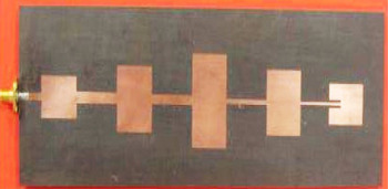
Certain low-frequency bands in 5G beamforming are discussed in detail here. In order to improve the overall performance of the antenna array, an MIS (matching-in-step) series-fed antenna array using five elements was introduced. The array was designed on Rogers RT 5880 substrate (ɛ r = 2.2, thickness = 0.787 mm, and loss tangent = 0.009) and the patch width was kept uniform, i.e. 2.42 mm. It was observed that the antenna array achieved better VSWR and radiation than the traditional designs. The antenna array resonated at 5 GHz (4.9–5.1 GHz band) and achieved −14 dB SLL. The design is shown in Fig. 24 [Reference Yuan, Yuan and Li115].
Tapered antenna array © [Reference Yuan, Yuan and Li115].

Two different types of Vivaldi antennas antipodal and tapered slot were used for electromagnetic beamforming for 1–5 GHz frequency range on RO4350B substrate (ɛ r = 3.48, thickness = 1.52 mm, and loss tangent = 0.0031) of size 40 × 50 mm2 [Reference Vu, Dooghabadi, Sudalaiyandi, Hjortland, Naess, Lande and Hamran116].
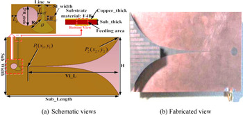
A homogenous anisotropic zero-index meta-materials (ZIM) Vivaldi antenna was used to improve the antenna gain, radiation efficiency, and directivity. The meander line slot was opted for the same and was designed on F4B (ɛ r = 2.65 and loss tangent = 0.001). The taper curve at the opening of Vivaldi antenna can be designed using equations (46) and (47) as follows:


where α is the opening rate and C 1 and C 2 can be calculated according to the points P 1 and P 2, shown in Fig. 25.
Vivaldi antenna structure © [Reference Zhou, Li, Zou and Cui117]. (a) Schematic views. (b) Fabricated view.

It was observed that the gain of the antenna can be improved by 2 dBi in the 9.5–12.5 GHz band, when a single layer IA-ZIM is used. With multiple layers, the gain can be increased by 4 dBi. The HPBW decreases by 45°, when multiple layers were used [Reference Zhou, Li, Zou and Cui117]. In another study, a broadband Vivaldi antenna was designed with beam switching features. The top layer of the design was printed on a Taconic TLY-5 board (ɛ r = 2.2, thickness = 0.78 mm, and loss tangent = 0.0009) and two symmetrical slots were added with a radiating angle of 90° at 40.6 mm equidistance to ensure wide bandwidth. The PIN diodes and bias networks are capable of supporting low power loss, high switching speeds, low parasitic resistance, and biasing, hence were added to the clover-leaf Vivaldi antenna. The study showed a way to increase beam steering modes from single to 23 − 1 modes using three PIN diodes. The diodes were used to switch between the three modes. Combination of modes 1 and 2 were achieved by forward biasing diode 3 (D3) and keeping D1 and D2 open circuited. Similarly, for modes 2 and 3, D2 and D3 were open circuited and D1 was forward biased [Reference Delphine, Hamid, Seman and Himdi118].
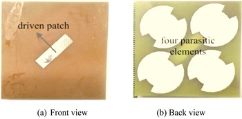
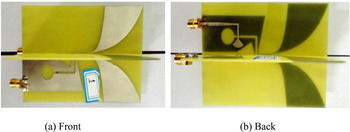
A high gain antenna with four parasitic elements was designed on FR-4 substrate (ɛ r = 4.4, thickness = 1.524 mm and loss tangent = 0.025) to provide a wideband. The antenna covered two bands: 5G (3.30–3.60 GHz) and Wi-MAX (3.40–3.69 GHz). The overall size of the substrate was 0.5λ × 0.5λ. The gain in the whole band was 5.62 dBi, and the efficiency was 81.9%. The design is shown in Fig. 26 [Reference Li, Lan, Ding and Guo119].
5G antenna © [Reference Li, Lan, Ding and Guo119]. (a) Front view. (b) Back view.

Similarly, a wideband, dual polarized, orthogonally placed Vivaldi antenna with improved balun was designed on an FR-4 substrate (ɛ r = 4.3 and thickness = 1 mm). An electromagnetic coupling from microstrip line to slot was used to feed each Vivaldi antenna, as shown in Fig. 27. The radiation patterns for the antenna at 2/2.5/2.7 GHz (2.0–3.5 GHz band) were wide, along with lower SLLs. It was observed that better results can be achieved with the improved balun feed. Around 25 dB port isolation was achieved in design [Reference Song and Zhou120].
(a) Dual polarized Vivaldi antenna © [Reference Song and Zhou120]. (a) Front view. (b) Back view.

A reconfigurable Vivaldi antenna can also be used at very high frequencies, i.e. THz, using a hybrid graphene metal with tapered slot edges. The chemical potential μ c increases the surface conductivity at a certain frequency, thus, in the case, μ c up to 0.25 eV was considered along with T = 300 K and transport relaxation time, λ = 1 ps. The size of the antenna was 2 × 1 mm2, as shown in Fig. 28. The maximum slot width was kept 0.9 mm. The design achieved frequency bands 630–930 GHz at μ c = 0.36 eV, and 280–1400 GHz at μ c = 0.5 eV. A maximum width, W of 0.8 mm was opted for the graphene structure. It was observed that the gain is reduced with the chemical potential and the bandwidth is increased. Also, the pure metal antenna had a higher reflection coefficient than graphene-metal-based antenna. The graphene-metal-based antenna achieved the re-configurability and had better gain and radiation efficiency than non-metallic graphene antennas [Reference Jin, Cheng, Chen, Zhou, Wu and Xu121].
Graphene-metal-based Vivaldi antenna © [Reference Jin, Cheng, Chen, Zhou, Wu and Xu121]. (a) Front view. (b) Back view.

High-frequency band antennas in 5G for beamforming
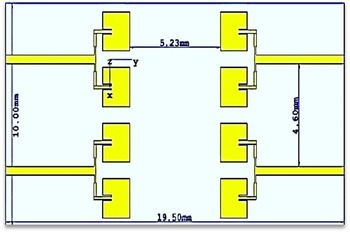
The antennas above 50 GHz are discussed here for 5G applications. A 2 × 4 MIMO antenna array with inset feed was designed to resonate at 60 GHz (50–70 GHz band). The MIMO structure comprised of four 1 × 2 power divider arms with different impedance feed combinations and inset feed rectangular antenna arrays. The antenna was designed on Rogers' RT 5880 substrate (ɛ r = 2.2, thickness = 0.16 mm, and loss tangent = 0.0009) of size 19.50 × 10.0 mm2. The design achieved 13.4 dBi gain along with 4.3 GHz bandwidth and a SLL of −5.1 dB. The design is shown in Fig. 29 [Reference Rahayu, Kurniawan and Sari122].
4 × 2 patch antenna array © [Reference Rahayu, Kurniawan and Sari122].

Similarly, a high gain microstrip antenna array with series-fed and parallel-fed networks was designed with 24 elements. The array had 6 × 4 patch elements on Rogers' RT/Duroid 5880 substrate (ɛ r = 2.2, thickness = 0.127 mm, and loss tangent = 0.0009) at 61.56 GHz (57.24–65.88 GHz band). The patch width ‘W’ and the patch length ‘L’ are calculated using equations (48) and (49).


where M and N are the non-negative integers, λ 0 and λ represent the free space and operating wavelengths, respectively, and ΔL is the patch length extension.
The feed length (LT 2), feed, the spacing between the array elements (LT 1), and inter-element space S, are calculated using equations (50)–(52), respectively. This antenna array achieved 19.26 dBi gain along with 2.64 GHz bandwidth. The overall size of the substrate was 27.05 × 31.62 mm2. The design is shown in Fig. 30 [Reference Rabbani and Ghafouri-Shiraz123].


where P, Q, and K are the non-negative integers (P = Q = 0 and K = 1 in this case).
Antenna array with 24 patches © [Reference Rabbani and Ghafouri-Shiraz123].

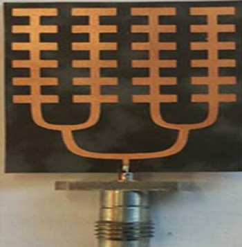
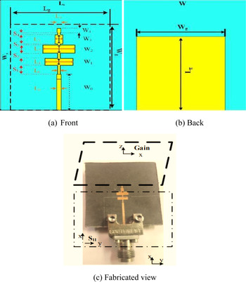
A microstrip antenna at 60 GHz (58–62 GHz band) millimeter-wave band having a circular contour on the outer side of feeding line of diameter 16.50 mm and four branches of antenna array was designed on an aluminum oxide substrate (ɛ r = 9.8, thickness = 0.012 mm, and loss tangent = 0.003). The maximum gain achieved by the design was 8.4 dBi for the mm-wave band [Reference Zhang, Pu, Xu, Liu and Wang124]. Similarly, a 57–69.4 GHz high gain antenna with 60 GHz resonant frequency was designed on the principle of log-periodic and Yagi–Uda antennas. The low loss Rogers' RT/Duroid substrate (ɛ r = 2.2, thickness = 0.254 mm, and loss tangent = 0.003) of size 30 × 30 mm2 was used for the design. The achieved bandwidth was 12.4 GHz. An efficiency of 91.2% and gain of 11.8 dBi were achieved at 60 GHz. The design is shown in Fig. 31 [Reference Issa, Fathalla, Ashraf, Vettikalladi and Alshebeili125].
Design based on principle of log-periodic and Yagi–Uda antennas © [Reference Issa, Fathalla, Ashraf, Vettikalladi and Alshebeili125]. (a) Front view. (b) Back view. (c) Fabricated view.

Beam steering
Unlike beamforming, beam steering is the technique that has the ability to change the directions of the main lobe of the radiation pattern. This can be achieved by either changing the phase of the signal or by switching between the elements. In this section, some cases and designs based on beam steering are discussed.
A beam steerable, four-patched antenna array comprising of two 3-defected microstrip structure (3-DMS) and 6-DMS power divider in the feed network was designed. It was observed that the phase shifts in 3-DMS power divider at four different states were 0, 0, 42, and −45°, and for 6-DMS these were 0, 0, 87, and −91°. Also, the direction of the main beam had the ability to switch at 0, 15, and −15°. The bandwidth in four states covered, all the frequencies in WLAN range, i.e. 5.2 GHz. The DMS structure had 8 × 2 mm2 slots and 10 mm thick microstrip line. The design is shown in Fig. 32 [Reference Ding, Guo, Qin, Bird and Yang126].
DMS power divider prototype © [Reference Ding, Guo, Qin, Bird and Yang126].

A defective ground structure is like a boon when better bandwidth, compact size, and harmonic suppression needs to be achieved. Moreover, a phased array antenna helps in achieving high gain and beam-steering ability. An antenna was designed on the Rogers' RO4533 substrate (ɛ r = 3.3, thickness = 0.762 mm, and loss tangent = 0.0025) of size 10 × 10 mm2 and had a sectored patch with 3 mm diameter. The antenna had ±30° beam steering capability for 26, 28, and 43 GHz frequencies. A minimum gain of 12 dBi was obtained for all the bands. The phase movement is calculated using equation (53) [Reference Anas, Shahid, Rauf and Shahid127].

where Δφ is the phase shift, d is the inter-element distance, and Θ s indicates the beam steering.
Microstrip antennas have been the most preferred ones when it comes to the matter of compactness, low profile, and lower manufacturing costs. The resonating frequency for any squared, circular, or rectangular patch can be derived using equations (54) and (55) [Reference Yadav and Malviya128]. But, it is very difficult to attain high gains using the same. Thus, MTMs are used to improve the gains. The MTMs have negative permittivity, i.e. ɛ < 0 [Reference Le, Ngyuen and Vuong129].


where c is the light velocity, a is the radius of the circular element, d is the distance from the feed point to the other side, and ɛ r is the dielectric constant.
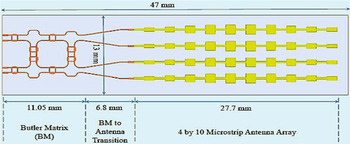
A 4 × 10 series microstrip patch antenna array fed by a Butler matrix was designed to operate at 60 GHz (55–65 GHz band). The design was implemented on Rogers' RO4003C substrate (ɛ r = 3.8, thickness = 0.2 mm, and loss tangent = 0.0027) of size 47 × 13 mm2, and the microstrip line structure over SIW structure was opted for the desired outcome. The array of patch antennas (in series) in the design were tapered in order to ensure more than 20 dBi gain for 4 × 10 antenna arrays and to limit the SLL. A 1 × 10 series-fed antenna array individually was able to achieve 87% efficiency along with 14.7 dBi gain. The antennas in array were placed at a distance of 2.67 mm. The port isolations were more than 15 dB. With 4 × 10 series fed antenna arrays, the system achieved 60% efficiency and 16.5 dBi gain. It was seen that 4 dB BW of two central planes and 3 dB BW of side beam were all around 25°, which ensured that the coverage of the 100° in H-plane. The design is shown in Fig. 33 [Reference Liu, Bshara, Tekin and Dandekar130].
60 GHz antenna array fed by Butler matrix © [Reference Liu, Bshara, Tekin and Dandekar130].

A MIMO antenna with flexible phased-array, having the transmit beamforming feature allowed the generation of multiple beams, which could be steered in the desired directions. This is possible due to the division of the system into sub-arrays. The sub-arrays provided flexible operating modes. Also, the system becomes capable to provide beams, which are range dependent [Reference Wang and Shao131].
All the discussed 5G beamforming antennas under all the frequency ranges and design structures are summarized and compared in Table 2. The antennas are compared on the basis of frequency band/bands, the number of elements, type of substrate and their sizes, gain, beam widths, efficiencies, and their applications in the wireless systems. The antenna designers are trying and implementing the beamforming and beam steerable antennas/arrays for various frequency bands, targeting to achieve an efficient, compact, high gain, high efficiency, and low losses, for several applications with the current and upcoming technologies for 5G and future generations. All the beamforming techniques are compared with their merits and demerits in Table 3.
Comparison of different frequency bands of beamforming antennas

Merits and demerits of different beamforming techniques

Conclusion
The 5G is the drastic technology and the present need of the mobile generation to achieve the high speeds of greater than 1 Gbps for uplink and downlink and low latencies, and is much better than the previous counterparts in terms of data rates, spectral efficiencies, capacity, and coverage. 5G beamforming is a technique with which the beams can be directed in the desired directions to cover the growing mobility of the existing users and cancel the interference in other directions, and to cooperate with the new generation of the technologies like AI and massive MIMO. All the frequency bands with Roger's Duroid (4003, 4350, 5880), tectonic, aluminum oxide, and FR-4 dielectric substrates have been included in beamforming for different beam widths ±10, ±25, ±35, and ±45° etc. for intended directions. The components of the beamforming like hybrid coupler, branchline coupler, broadband coupler, and WPD have wide applications for the smart antenna designs, and have been discussed in details here with mathematical modeling. Different designs for 5G beamforming applications have been incorporated in this paper with their frequency bands, efficiency, size, isolation, beam widths, and all the possible aspects. Various types of beamforming approaches like analog, digital, hybrid, switched, and adaptive have been discussed in detail in this paper. The study of the Butler matrix is one of the important aspects of beamforming techniques.
Supplementary material
To view supplementary material for this article, please visit https://doi.org/10.1017/S1759078720001622.
 Leevanshi Rao is currently pursuing Master of Engineering in Electronics and Telecommunications from Shri G.S. Institute of Science and Technology, Indore, Madhya Pradesh, India since 2018. She received her B.Tech in Electronics and Communications from Charotar University of Science and Technology, Charusat-Changa, Anand, Gujarat, India in 2018. Her current research interests include compact MIMO and array antennas for high data rate communications for 5G.
 Mohit Pant received his M.E degree in Digital Communication from the Institute of Engineering & Technology, DAVV, Indore, India in 2012 and the B.E degree in Electronics and Communication from the Laxmi Narayan College of Technology, Bhopal (M.P.), India in 2004. Currently, he is working as an Assistant Professor in Mahakal Institute of Technology, Ujjain (M.P.) India and pursuing his Ph.D. degree from Ujjain Engineering College, Ujjain, India. His current research interest includes millimeter-wave antennas and arrays for wireless applications, and multiple-input–multiple-output (MIMO) antennas for high data rate communications for 5G. He is a member of the IEEE.
 Dr. Leeladhar Malviya received his Ph.D. from IIT Roorkee, India in 2017. He received his ME in Electronics and Telecommunication from Shri G. S. Institute of Technology and Science, Indore (M.P.), India, in 2008, and BE in Electronics and Communication from the Government Engineering College, Ujjain (M.P.), India, in 1998. Since 2001, he has been with Shri G. S. Institute of Technology and Science, Indore (M.P.), India, and serving as an Associate Professor. His current research interests include compact multiple-input–multiple-output (MIMO) antennas for high data rate communications for 4G, 5G, and THz planar microstrip antennas, fractal antennas, and metamaterial antennas for communication. He is a Senior Member of IEEE, Fellow Institution of Electronics and Telecommunications Engineers (F-IETE, India), Institution of Engineers (IE, India), and Indian Society for Technical Education (ISTE). He is the reviewer of the Elsevier, IEEE, IET, PIER journals, and Wiley journals. He is also the author of a book on MIMO antennas.
 Ajay Parmar received his M.Tech from NIT Silchar (Assam), India in 2014. He received his B.E. in Electronics and Communication, from Rewa Engineering College, Rewa (M.P.), India in 2012. Since 2018, he has been with Shri G. S. Institute of Technology and Science, Indore (M.P.), India and serving as an Assistant Professor. His current research area is MIMO and array antenna design for 5G. He is a Member of Indian Society for Technical Education (ISTE).
 Prof. Sandhya Vijay Charhate is currently working in Shri G. S. Institute of Technology and Science since 1985. She received her ME in Computer Science from DAVV University, Indore (M.P.), India, in 1991, and BE in Electronics and Communication, from the Pune University, India, in 1981. She is a Member of Institution of Engineers (IE, India).