Introduction
Demand for low-cost wireless wearable waterproof flexible electronics is rapidly increasing nowadays. Inkjet-printed electronics on organic paper and other conformal materials have been proposed as a reduced fabrication cost and biocompatible solution for wearable biomonitoring devices [Reference Kim1, Reference Anagnostou2], but they are vulnerable to ambient moisture, especially when implemented on hydrophilic (e.g. paper-based) substrates. There have been numerous research efforts in the past to realize washable/waterproof antennas, most of them concerning textile antennas that involve the integration/realization of antennas with commercially available fabrics [Reference Zhu and Langley3, Reference Heikkinen, Laine-Ma and Kivikoski4]. This approach has the advantage of the direct integration of the antenna with clothes in high-flexibility configurations, but the metallic area of the antenna is typically exposed to the external environment without any protective layers, which commonly results in the quick rusting or degradation of the antenna performance.
There are many types of conformal coating technologies to protect circuits/devices from the harsh environment such as acrylic, silicone, and Parylene coatings. The acrylic coating is not resistant to abrasions, chemicals, and subject to environmental regulations. The silicone coating is susceptible to abrasion due to its low cohesive strength. It also has relatively high dielectric constant (ε r ≈ 10) compared with the available flexible substrates such as polyethylene terephthalate (PET), and paper. The high dielectric constant increases the capacitance of microwave structures such as coplanar waveguide lines as well as parasitic capacitances that could potentially lead to shifting of the resonant frequency after the coating. The silicone coating process is a wet process that moisture sensitive substrates like paper can experience mechanical stress during/after drying process. However, the Parylene is a well-known stable chemical and has high cohesive strength [Reference Sharifi5]. It has a close dielectric constant (ε r ≈ 3) value to the organic substrates and low loss (tan δ = 5 × 10⁻⁴ ~ 2.1 × 10⁻³). In addition, the deposition process of the Parylene is a completely dry process that can occur at room temperature like the other coating processes and transparent after the deposition. These properties of Parylene are compatible with inkjet printing technology on paper. Therefore, in this paper, Parylene coating for inkjet-printed antennas is introduced and its performance is demonstrated not only to overcome “environmental exposure” limitations of current inkjet-printed antennas but also to realize the first inkjet-printed waterproof antennas. The Parylene is a stable, biocompatible, and conformal polymer coating material. It is usually applied to various electronics for many purposes, such as encapsulating a circuit to prolong its lifetime [Reference Heikkinen, Laine-Ma and Kivikoski4, Reference Sharifi5]. It is utilized as a microwave substrate or a protection film for implantable applications, such as coating for pacemakers and stents. As a proof of concept of Parylene-C's waterproof characteristics for inkjet-printed circuits, it has been deposited on top of an inkjet-printed dual-band antenna on a paper substrate that has been immersed in water for a prolonged time. The Parylene coating covers the printed metal layer and resin-coated photo paper. It separates the printed antenna from water and ambient humidity.
This paper is structured as follows. In the section “Antenna design and Parylene coating”, the design and the inkjet printing of the dual-band antenna on paper as well as the deposition process of Parylene-C are described. The section “Antenna measurement” covers the measurements and the discussion of the performance-enhancing effect of Parylene-C coating for extended exposure to humidity.
Antenna design and Parylene coating
Inkjet-printed dual-band monopole antenna
A co-planar waveguide (CPW) fed monopole antenna (Fig. 1) is designed to investigate the effect of the Parylene coating. The CPW technology is chosen due to its single metal layer feature that facilitates its fabrication especially utilizing inkjet printing technology. The overall size of the complete antenna/feed topology is 90 mm × 100 mm with a radiator of 36 mm × 45 mm optimized to operate around 900 MHz. The distance between the slot and the ground is 39.5 mm. A horizontal slot is added perpendicular to the monopole axis in the middle of the radiator. It excites a higher order monopole mode which resonates at 2.4 GHz. The slot-loaded dual-band antenna structure is chosen due to the vulnerability of this type of inkjet-printed antenna on the paper substrate to the ambient humidity. Water-absorbed paper causes not only a drastic change in its dielectric constant (ε r) but also a physical/shape modification of curling or expansion. The thin traces around the radiator slot can be easily broken due to such a physical transformation of the substrate, thus resulting in the eventual vanishing of the slot-induced resonance around 2.4 GHz, irreversibly.
Antenna geometry. The thickness of the paper substrate is 228.6 µm and the gap of CPW line is 250 µm.

For the fabrication, the printing resolution was kept to 1270 dpi. In this work, the printed antenna and the paper were sintered at 120°C for 4 h to maintain flexibility of photo paper because the resin-coated photo paper loses its flexibility when it is exposed to high temperature as shown in [Reference Abutarboushm, Farooqui and Shamim6]. The pattern has a DC conductivity value of 1.16 × 10⁶ S/m with the roughness of 1 µm when the pattern is printed three times. The dielectric constant (ε r) of 228.6 µm thick paper substrate is 3.2 ~ 3.6 and the loss tangent (tan δ) is 0.06 throughout the frequency band of interest [Reference Kim1].
Properties of Parylene
In this section, the properties of Parylene coating are discussed. There are two Parylene types, the C and N, that look similar in their commercial form of a powdered dimer, but they feature different high-frequency characteristics due to their slightly different molecular structure. The dielectric constants of Parylene-C and -N are 2.95 and 2.4, respectively. The Parylene-C has loss tangent (tan δ) of 5 × 10⁻³ while Parylene-N has that of 2.1 × 10⁻⁴ at the operation frequency bands of the proposed antenna (900 MHz and 2.4 GHz) [Reference Heikkinen, Laine-Ma and Kivikoski4]. Both have low water absorption rate which is lower than 0.1% after 24 h in the water [Reference Sharifi5]. The reported contact angle of a water drop on Parylene-C is about 108° which is comparable with that of a water drop on a lotus leaf (~147°) for the comparison. The contact angle is the angle between a liquid interface and a solid surface. A hydrophobic surface has the higher contact angle than a hydrophilic surface. The deposited Parylene layer has a uniform surface because its root mean square roughness is as small as approximately 4.6 nm [Reference Lee7]. In addition, Parylene is a flexible material since it has low Young's modulus of 2.76 GPa. This value is close to that of PET which is well known and widely used as a flexible substrate (2.0 ~ 2.7 GPa) [Reference Maeng8]. Therefore, the Parylene material has a great potential to be used for the environmental protection and sealing of flexible radio-frequency (RF) devices and circuits. The deposition rate of Parylene-C is about 5 µm/h while that of Parylene-N is 0.75 µm/h. The loss tangent of Parylene-C is much higher (about 24 times) than Parylene-N but it is still a small value while the thickness of the Parylene film is electrically thin for the frequency range of operation. The thickness of the deposited Parylene layer can be controlled by the amount of the Parylene powder placed in the vaporizer chamber (Fig. 2). In this work, Parylene-C is chosen as a deposition material because its dielectric constant is close to that of the paper substrate, its low cost, and its deposition time takes less time than Parylene-N.
General Parylene deposition system.

Deposition process
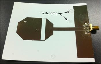
The deposition process is depicted in Fig. 2. It happens when the Parylene dimer is converted to a polymer film at room temperature in the deposition chamber under very low pressure around 0.1 torr. The vaporization of the solid Parylene dimer at about 175°C is the first step. The second step is to split the dimer vapor in two methylene-methylene bonds at approximately 690°C to make stable monomeric diradical, para-xylylene in the pyrolysis furnace. The monomeric vapor, para-xylylene, enters the deposition chamber, and it polymerizes on the substrate at 25°C. Lastly, the extra monomeric vapors are trapped in the cold trap to prevent the rest gases from leaking. Therefore, the deposition occurs at room temperature and is a completely dry fabrication process that is compatible with inkjet printing technology. As Parylene film thickness of 1 ~ 10 µm demonstrates good water hermeticity, the minimum thickness of 1 µm was utilized in the benchmarking antenna of this paper [9]. The fabricated antenna with the Parylene layer is shown in Fig. 3.
Fabricated printed antenna with 1 µm thick Parylene-C coating.

Antenna measurement
Reflection coefficient (S 11)
The reflection coefficient (S 11) values of the designed antennas were measured as shown in Fig. 4. The measured and simulated data for the reflection coefficient (S 11) of two identical antennas one with and another without Parylene coating are presented in Fig. 4(a) verifying that the results are almost identical for both cases. For the comparison, the effect of the silicone coating is also included. The effect of a 50 µm thick (available minimum thickness) silicone layer is notable at 2.4 GHz. The fabricated antenna prototypes with/without the Parylene coating are submerged in the distilled water to investigate their waterproof capability. Waterdrops on the antenna were wiped-out by tissues and residual humidity was dried by an air dryer. Figure 4(b) shows the measured S 11 after 4 days in the water. The antenna without coating has lost its dual-band property since the antenna does not resonate at 2.4 GHz anymore. The difference of S 11 between the antennas is clearer after 48 days in the water. The antenna without Parylene coating has lost its antenna defining properties because it does not resonate anymore throughout the frequency range of interest as shown in Fig. 4(c). However, the antenna with Parylene coating still maintains its frequency response even though it has been in the water for 48 days. On top of that, there are almost no “time-dependent” changes between S 11 plots for 4 or 48 days of exposure to water. Figure 5 shows the antenna after 48 days in the water. There are no observable changes of the coated antenna comparing Figs 2 and 5(a) while the shape of the antenna without coating is destroyed as shown in Fig. 5(b). This result suggests that the Parylene deposition of the inkjet-printed antenna on organic paper substrate successfully protects the antenna from moisture, and it enables the inkjet-printed electronics to be waterproof.
Reflection coefficient (S 11) measurement: (a) antennas with/without Parylene coating, (b) antennas in the water for 4 days, and (c) antennas in the water for 48 days.

Comparison of the antennas after 48 days in the water: (a) the antenna with a Parylene coating, and (b) the antenna without coating.

Antenna gain and radiation pattern
The radiation pattern and the gain of the two antennas are measured and compared with simulations in Fig. 6. The antenna gain after 48 days in the water is presented since the antenna has lost its electrical functionality after 48 days in the water as shown in Fig. 4. The discrepancies between the measurement and the simulation are due to the thin metal thickness of the printed antenna. It is hard to model the metal thickness effect of the printed antenna on paper because the surface roughness of paper is comparable with the metal thickness of the inkjet-printed antenna resulting in low radiation efficiency than simulation [Reference Kim1]. The measured radiation efficiency of the antenna at 900 MHz is 0.35 and that of the antenna at 2.45 GHz is 0.58. The radiation patterns at 900 MHz and 2.45 GHz are shown in Figs 7 and 8.
Gain of the antenna at (a) 900 MHz GSM band (b) 2.45 GHz ISM band.

Radiation patterns of the antenna at 900 MHz (a) x–z plane (H-plane, ϕ = 0) (b) y–z plane (E-plane, ϕ = 90).

Radiation patterns of the antenna at 2.45 GHz (a) x–z plane (H-plane, ϕ = 0) (b) y–z plane (E-plane, ϕ = 90).

The simulated and measured gain values are relatively similar but the minor differences between them can be attributed to slight misalignment errors during the measurement process. The measured radiation patterns with/without the Parylene coating in free space were on top of each other. The normalized gain patterns (dBi) are plotted on x–z and y−z plane, respectively. Y–z plane corresponds to E-plane (Figs 7(a) and 8(a)) and x–z plane corresponds to H-plane (Figs 7(b) and 8(b)). It is clear that the Parylene coating does not affect the antennas’ performance even after the waterproofing test because the gain and radiation pattern do not change after the deposition of the Parylene coating. It is because the dielectric constant of the deposited Parylene-C layer (ε r, parylene = 3.0) is pretty close to that of paper substrate (ε r, paper = 3.2) as well as the thickness (t = 1 µm) of the coating layer is negligible. The coating thickness at each operation frequency compared with the wavelength in the free space is about 3 × 10⁻⁶λ0 at 900 MHz and 8 × 10⁻⁶λ0 at 2.45 GHz, respectively. It is reasonable that radiation patterns with the coating after the water-proofing test (after 4 days or 48 days in the water) are identical to the patterns of the antenna without the coating before the water-proofing test when the frequency response (S 11 shown in Fig. 4) is unchanged. The conductivity of the printed sliver nano-particle ink doesn't change because the antenna performance parameters are not much changed before/after the water-proofing test.
Conclusion
In this work, Parylene-C is deposited on an inkjet-printed prototype of a dual-band CPW-fed monopole antenna on paper to demonstrate its capability to enable waterproof inkjet-printed RF topologies. The thickness of the deposited Parylene layer is about 1 µm, and antenna performance characteristics, such as reflection coefficient (S 11), gain and radiation patterns are barely affected by the coated Parylene layer. A hydrophobic surface is successfully formed on the whole area of the inkjet-printed antenna due to the Parylene layer, and the antenna performance remains virtually the same after being submerged in the water for 4 or 48 days. This coating technique can be easily applied to a variety of inkjet-printed RF geometries to protect them from exposure to moisture and potentially lead to the first generation of inkjet-printed waterproof wearable RF electronics.
Acknowledgement
This work was supported by Pusan National University Research Grant, 2018.
 Sangkil Kim received the B.S. degree in electrical and electronic engineering (magna cum laude) from Yonsei University, Seoul, Korea, in 2010, and the M.S. and Ph.D. degrees in Electrical and Computer Engineering from the Georgia Institute of Technology, Atlanta, in 2012 and 2014, respectively. In 2015, he joined Qualcomm, Inc., RFIC design group, San Diego, CA, USA as a Senior EM Engineer, involved with 5 G mmWave phased antenna array module. He is currently an Assistant Professor with Department of Electronics Engineering, Pusan National University, Busan, South Korea.
 Manos M. Tentzeris received the Diploma degree in electrical and computer engineering (magna cum laude) from the National Technical University of Athens, Athens, Greece, and the M.S. and Ph.D. degrees in electrical engineering and computer science from The University of Michigan at Ann Arbor. He is currently a Professor with School of Electrical and Computer Engineering, Georgia Institute of Technology, Atlanta.