1. Introduction
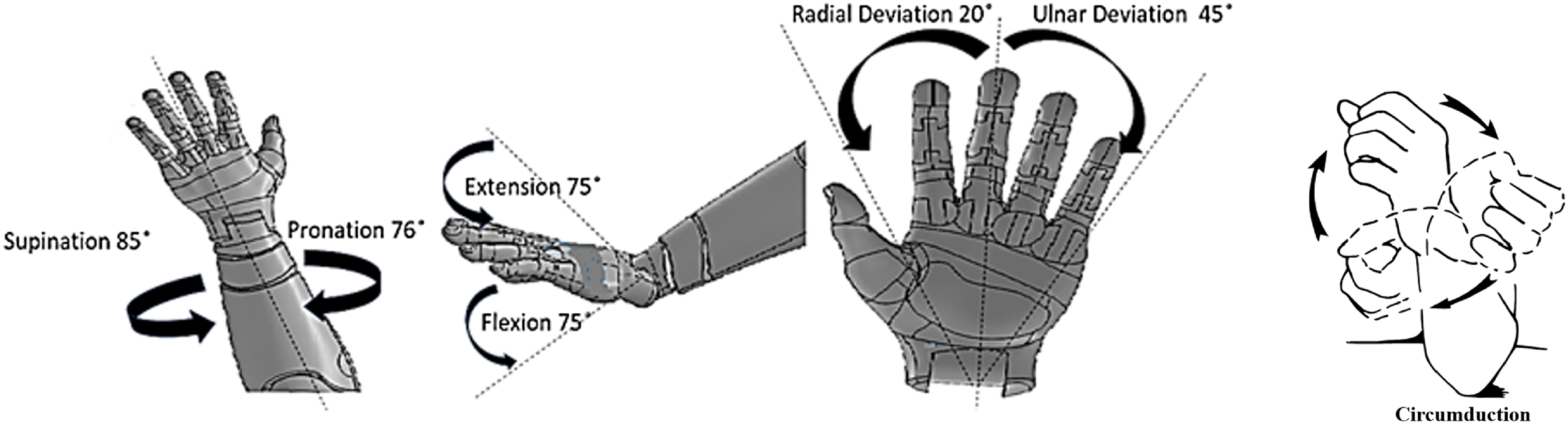
Rehabilitation using robotic devices has now become an integral part of the field of physiotherapy for quicker recovery [Reference Okajima, Alnajjar, Costa, Asin-Prieto, Pons, Moreno, Hasegawa and Shimoda1, Reference Yang, Zhang and Fu2]. The human biomechanics of the wrist involves three degrees of freedom (DOF) for roll-pitch-yaw motion, typically expressed as flexion-extension, ulnar-radial deviation, and circumduction. However, it is important to note that supination-pronation, often modeled as part of wrist motion in anthropomorphic robotic arms [Reference Shaaban, Pereira, Williams and Lees3], primarily occurs at the forearm due to the relative mobility of the radius and ulna through the proximal and distal radioulnar joints [Reference Youm, Dryer, Thambyrajah, Flatt and Sprague4], as illustrated in Figure 1. Although the wrist is a distinct part of the upper limb, its role in Activities of Daily Living (ADL) is closely integrated with the movements and functions of the forearm [Reference Kim and Deshpande5].
There are many researches published addressing the different models of wrist exoskeletons. The Universal Haptic Drive [Reference Oblak, Cikajlo and Matjaĉić6] and Rice Wrist [Reference Gupta, O‘Malley, Patoglu and Burgar7] were among the popular wrist exoskeleton devices between 2010 and 2015. However, newer and more advanced wrist exoskeleton systems have been discussed extensively in recent systematic reviews, such as those by Huamanchahua et al. [Reference Huamanchahua, Toledo-Garcia, Aguirre and Huacre8], Perrelli et al. [Reference Perrelli, Lago, Garofalo, Bruno, Mundo and Carbone9], and Galbert and Buis recent systematic reviews, such as those[Reference Galbert and Active10], which highlight innovative devices, emerging trends, and advancements in rehabilitation-focused exoskeletons. The Supervised Care and Rehabilitation Involving Personal Tele-robotics (SCRIPT) [Reference Amirabdollahian, Ates, Basteris, Cesario, Buurke, Hermens, Hofs, Johansson, Mountain, Nasr, Nijenhuis, Prange, Rahman, Sale, Schätzlein, van Schooten and Stienen11] is an exoskeleton that aims to demonstrate the design and development steps involved in creating a complex intervention. This work also explores the development of a device for home-based wrist-hand rehabilitation. The stability of the wrist is very much dependent on the grasping capacity and human-robot physiological coupling [Reference Rahman, Rahman, Cristobal, Saad, Kenné and Archambault12].
The wrist can typically rotate between 76° and 85° for pronation and supination, bend forward and backward up to 75° each, and tilt side to side within a range of 20° to 45° [Reference Bajaj, Spiers and Dollar13]. Investigations have shown that the functional DOF needed to comfortably carry out ADLs typically ranges between 75°/65° for supination/pronation, 40°/40° for extension/flexion, and 10°/30° for radial/ulnar deviation [Reference Fan, Wei and Ren15]. The function of fingers is intricate and multifaceted, owing to the complexity of their DOF. Notably, the thumb possesses five DOF, while the other fingers have four. The articulation of fingers involves a high level of flexibility, making the generation of their DOF particularly challenging. Extensive research has delved into this domain, resulting in significant advancements aimed at providing all DOF [Reference Iqbal, Ahmad and Malik16, Reference Chiri, Giovacchini, Vitiello, Cattin, Roccella, Vecchi and Carrozza17, Reference Cempini, Cortese and Vitiello18]. However, the essential functional degree of hand functionality lies in its ability to grasp and release objects. Thus, the manipulation of the hand to open and close, facilitating object interaction, is paramount in defining its functional DOF [Reference Gupta, Singh, Verma, Mondal and Gupta19].
Biomechanical movements of the wrist joint [Reference Bajaj, Spiers and Dollar13, 14].

Many studies have explored the use of hand exoskeletons in stroke rehabilitation, utilizing flexible splints and 3D printing for manufacturing the exoskeleton structure [Reference Barria, Riquelme, Reppich, Cisnal, Fraile, Pérez-Turiel, Sierra, Aguilar, Andrade and Nuñez-Espinosa20]. The Maestro Hand Exoskeleton is an example where it mimics the properties of the hand and wrist during grasping and manipulation for stroke rehabilitation [Reference Agarwal, Neptune and Deshpande21]. In terms of specific applications, robotic upper limb exoskeleton devices have been tested for stroke rehabilitation, with interfaces designed to facilitate forearm exercises and improve hand and wrist mobility [Reference Alhamad, Seth and Abdullah22]. Evidence of neuroplasticity has been observed with the use of robotic hand exoskeletons in post-stroke rehabilitation. These devices show potential to positively affect brain activity and improve joint function [Reference Singh, Saini, Kumar, Srivastava and Mehndiratta23]. Bilateral soft robotic exoskeletons also mimic healthy limb motion to aid hand and wrist rehab in individuals with weakness [Reference Ridremont, Singh, Bruzek, Erel, Jamieson, Gu, Merzouki and Wijesundara24]. Using electromyography (EMG) signals for hand prosthesis control shows a potential for integrating EMG into rehab exoskeletons [Reference Sánchez-Velasco, Arias-Montiel, Guzmán-Ramírez and Lugo-González25, Reference Liu, Liang, Murata, Li, Ueda, Matsuzawa and Zhu26]. The integration of sensors and actuation technologies in exoskeletons has been a key focus in the field, with specific applications in stroke rehabilitation techniques. Researchers have also made significant advancements in EEG-based exoskeleton systems, highlighting the importance of technological advancements in signal processing for controlling such systems [Reference Mathew, Thomas, Navaneeth, Sulaiman, Amudhan and Sudheer27]. In the realm of brain-computer interfaces, motor imagery-based systems have shown potential for enhancing upper limb post-stroke rehabilitation therapy. The increasing popularity of EEG as a control signal underscores the potential for integrating EEG technology into hand exoskeletons for rehabilitation purposes [Reference Wang, Zhang, Wang, Yuan and Zhang28].
In this paper, the authors try to come up with a novel design using concept screening and scoring processes. The unique design features support hand opening and closing for targeted finger rehabilitation, while wrist flexion and extension are achieved using a linear actuator that controls the movement of the wrist plate. Pronation and supination motions of the lower arm, from the elbow to the wrist joint, are actuated by a DC motor with a gear arrangement, ensuring smooth and precise operation. Additionally, the ulnar-radial deviation is facilitated through a motor-driven piston holder mechanism, allowing controlled movements within specified angular limits on the forearm plate.
A unique aspect of the design lies in its modularity, allowing the four DOFs to be actuated either simultaneously or independently, based on individual rehabilitation needs. This includes the ability to perform hand open-close movements and wrist motions independently, enhancing the system’s adaptability and functionality compared to existing designs. Moreover, the system enables all degrees of freedom of the wrist and hand to be controlled within a single piece of equipment, making it more efficient and versatile. Then the selected design is subjected to Kinematic and Dynamic modeling for understanding the motion in various combinations. A prototype of the exoskeleton is 3D-printed using PLA material to ensure both structural integrity and ergonomic compatibility. The research also explores several control strategies, including manual control, master-slave control, and control based on the EEG dataset. The manual control mode enables user-defined or range-based movements, guided by pre-input data through an intuitive interface. A master-slave control approach allows the exoskeleton to replicate the motions enacted by a physiotherapist or caregiver, providing an interactive rehabilitation experience. Additionally, the system leverages EEG datasets to lay the foundation for an intention-based control system, where real-time EEG data can enable movements driven by the user’s neural activity [Reference Pooja, Pahuja and Veer29]. Although this study primarily focuses on analyzing hand open-close movements due to the availability of EEG datasets specific to this functionality, it demonstrates the potential for expanding this approach to other degrees of freedom in future implementations. These novel control strategies offer versatile options for rehabilitation, ensuring both user-centric customization and advancements toward intention-driven systems. Unlike earlier models, which often lacked comprehensive functionality, this system addresses multiple DOFs in the wrist and hand, enabling targeted and customizable rehabilitation. The inclusion of a hand opening and closing mechanism, alongside support for wrist flexion/extension, pronation/supination, and radial/ulnar deviation, provides enhanced precision and adaptability. These features make the design a robust and user-centric solution and set a new benchmark for rehabilitation technologies.
2. Design thinking and concept selection
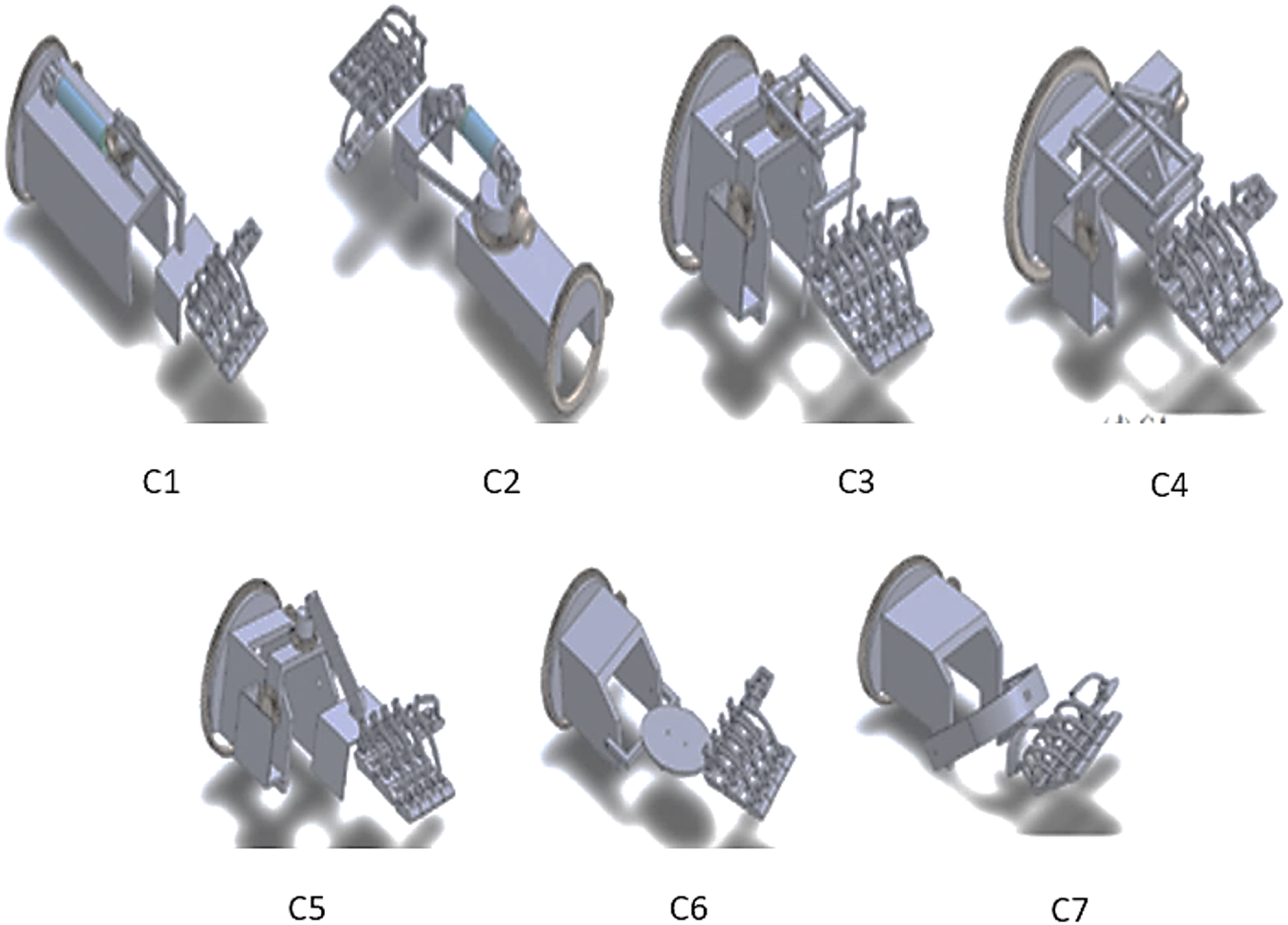
The proposed exoskeleton design is focused on a versatile and portable exoskeleton with the maximum DOF and ROM. A rough idea of technology and the principle of operation can be obtained from conceptual design. As mentioned in the introduction the authors try to achieve all the DOF of the wrist joint for the ADL. Seven designs were drawn using Solidworks with the relevant anthropometric data [Reference Garrett30] using various mechanisms to address motions like flexion/extension, Ulnar/radial deviation, and pronation/supination. The developed concepts are illustrated in Figure 2. In all concepts, the three DOFs of the wrist and open-close motion of hands are made possible. In ADL, pronation/supination motion is achieved mostly in combination with the lower arm area. Hence, the functional DOF in all the design concepts is developed based on a gear rack mechanism which allows the free rotation of the lower arm. The arrangement for the open-close motion of the hand in all concepts is the same. In C1, a linear actuator with a rotary arrangement along the slot is used to get Flexion/Extension motion and Ulnar/Radial motion, respectively. However, in C2 the linear actuator position and rotary arrangement position interchange and slot are removed to get the same motion. In C3, two rotary arrangements with the ladder-like structure are used. C4 concepts differ in their direct connection arrangement. C5 concepts use a wiper mechanism for Ulnar/Radial motion. In C6 concepts, C shape with disk hinge arrangement is used for getting the Flexion/Extension and Ulnar/Radial motion. Two U-shaped connectors arranged in a T shape for getting the Flexion/Extension and Ulnar/Radial motion are used in concept C7.
2.1. Concept screening and scoring
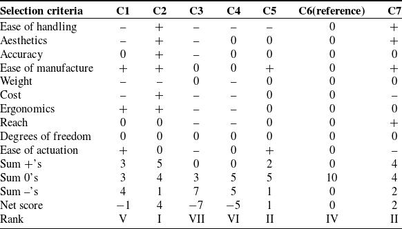
Concept screening and scoring are techniques used to evaluate and prioritize different design concepts or ideas based on predefined criteria. These techniques help designers make informed decisions about which concepts are most promising and worthy of further development. In concept screening, a few best solutions are selected based on a quick assessment [Reference Sunil and Sudheer31]. A suitable screening matrix is used to assess the different conceptual designs. In concept screening, a reference design is taken from the different designs created and others are rated based on the reference design: a positive “+” for superior design, a negative "−" for inferior design, and a zero "0" for equal design. The concept with the highest net score is treated as the best design and those with the least are treated as the worst design. The concept screening table matrix is shown in Table I. The selection criteria are listed based on the discussion with physiotherapists and design engineers from clinics and industries. Then four best designs based on the ranking are selected further for concept scoring. Based on the score concepts, C2, C5, C6, and C7 were selected to proceed to concept scoring. Minor modifications in concept C2 were also carried out before concept scoring
Concept screening.

Developed concepts.

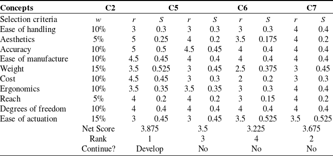
Concept Scoring analyzes the concepts in depth and sorts out the best ones from them. Based on the literature survey and feedback from the consumer, the weightage for the selection criterion is finalized. The scores for each concept are obtained by multiplying the weightage and rating. The equation for weighted score is given as
 \begin{equation}S_{j} = \sum\limits_{i = 1}^{n}{r_{ij} w_{i}}\end{equation}
where
 $r_{ij}$
is the raw rating for concept j for the i
th criterion,
 $w_{i}$
is the weighting for the ith criterion, n is the number of criteria, and Sj
is the total score for concept j [Reference Sunil and Sudheer31]. Weight and ease of actuation were given the highest weightage of 15%, aesthetics and reach the least weightage of 5 %. Other criteria were given as 10%. The criteria weights were determined through a structured, two-step process involving clinicians and medical experts. A broader matrix of criteria was initially developed based on an extensive review of the relevant literature. In the first step, a discussion was conducted to identify and finalize 10 criteria from this matrix, using opinion-based feedback from participants. In the second step, each expert assigned preference scores to the finalized criteria based on their importance. The weights were then calculated as percentage values derived from the aggregated preference scores of all participants. The concept scoring table matrix is shown in Table II. Based on the net score value concept C2 got the 1st position and it got selected for further development.
Concept scoring.

W–Weightage R–Rating S–Score
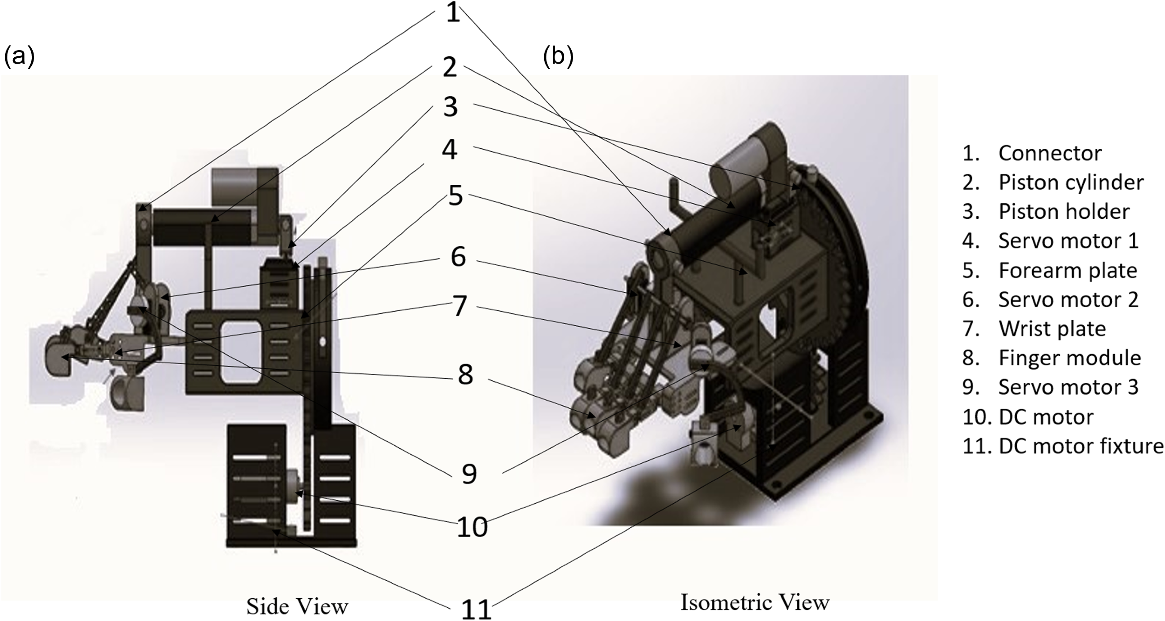
The design of the finger is based on the open-close movement of the hand. The dimension of the selected design is modified based on anthropometric data [Reference Garrett30]. The final modified selected wrist hand exoskeleton designis shown in Figure 3.
Final design model.

3. Kinematic analysis
By employing kinematic equations, forward kinematics evaluates the position as well as the orientation of the end effector concerning the specified values of the joint parameters. The end effector’s attitude about the joint parameters is determined by forward kinematics. If the end-effector’s posture is known, inverse kinematics may be used to calculate the joint angle. This section uses Denavit and Hartenberg’s (DH) technique to explain the forward and inverse kinematics of the wrist and hand exoskeleton.
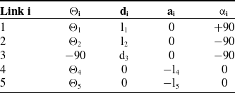
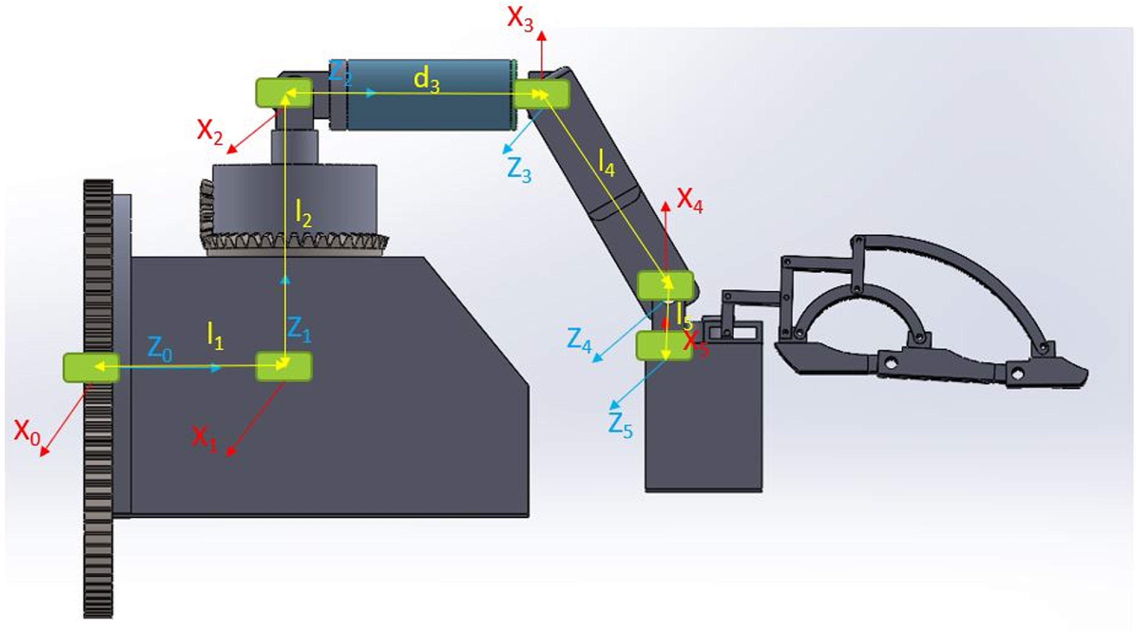
Figure 4 represents DH frame representation of exoskeleton with {0} as global frame and remaining {1},{2},{3},{4} and {5} the local frame. Once the frame assignment is done based on the DH method then joint link parameters such as link length (ai), link twist (αi), Joint distance (di), and joint angle (θi) for the different links are tabulated as in Table III.
DH parameter table.

DH parameter representation.

The individual transformation matrix from 0T1, 1T2, 2T3, 3T4, 4T5 can be calculated. The final transformation matrix of the exoskeleton can be obtained by multiplying the individual transformation matrix as shown in equation 4. Thus, the position and orientation of the end effector concerning the base frame can be found.
 \begin{equation}^0T_{5} = (^0T_1) (^1T_2) (^2T_3) (^3T_4) (^4T_5)\end{equation}
To obtain an inverse kinematic solution, the final known matrix and 0T5 are equated for getting different sets of feasible equations and hence solving the equation using MATLAB.
4. Trajectory planning and dynamic analysis
A trajectory is related to the timing at which each part of the path is attained. The method with which an exoskeleton is moved from one location to another in a controlled manner is referred to as trajectory planning. The exoskeleton’s initial position and orientation are known, and the final joint angles for the desired position and orientation are calculated using inverse kinematic equations. The trajectory of each exoskeleton joint, however, must be planned separately. Trajectory planning is done based on the assumption of a cubic spline equation. The exoskeleton joint’s movement must be planned independently, with a value for each joint movement over 3 s. The initial and final pose of end effector joint parameter ranges are calculated from kinematic equation 3.
 \begin{equation}\theta(t)=c_0 + c_1 t + c_2 t^2 + c_3 t^3\end{equation}
where
 $\theta(t)$
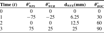
is the joint parameter at time t and c0, c1, c2, and c3 are constants. Table IV is made based on the ROM of different joints. The value change for the given time interval for the θ1 is −75, 0, 75, θ2 is −25, 0, 25, and d3 is 0, 12.5, 25 mm respectively as shown in Table IV.
Trajectory data.

From this data constants
 $c_0, c_1, c_2, c_3$
are calculated for each joint and substituted in equation (3).
Eq. (4- 6) gives polynomial functions for the wrist joints.
 \begin{align}&\qquad\quad \theta_{WPS}=-275\, t + 250\; t^2 - 50\; t^2 \end{align}
 \begin{align}& \theta_{WUR}=-\,(-275/3)t +(250/3) t^2 -(50/3) t^3 \end{align}
 \begin{align}& d_{WFE}=-\,(275/24) t -(175/24)t^2 -(25/12) t^3 \end{align}
 \begin{align}&\,\,\, \theta_{HOC}=-2.7577 t -15.7084 t^2 - 47.2299 t^3 \end{align}
where
 $\theta _{WPS} \theta _{WUR}d_{WFE}\theta _{HOC}$
are the joint variables corresponding to wrist supination/pronation, radial/ulnar deviation, extension/flexion, and hand open and close. Assume that the joint’s location, velocity, and acceleration, as well as the kinematics and mass distribution of the robot, can determine the joint torques necessary to produce the motion. The Luh, Walker, and Paul approach described in [Reference Luh, Walker and Paul32] provides the foundation for the algorithm that is being given. Forward kinematics and dynamic Lagrange equations are related in the context of analyzing the motion and dynamics of a robotic system.
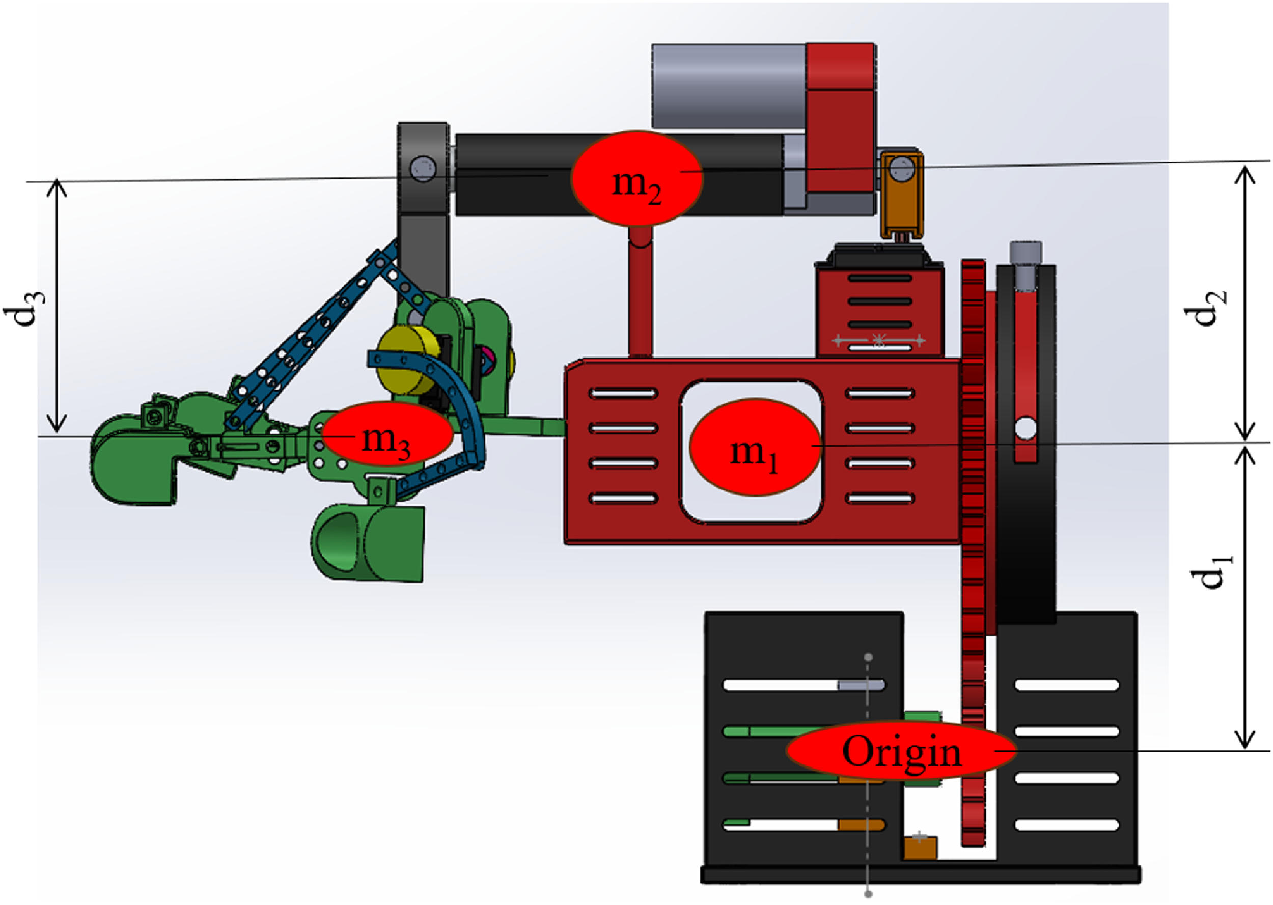
Dynamic Lagrange equations describe the dynamics of a mechanical system. These equations take into account the masses, inertia, forces, and accelerations of the system. They provide a mathematical framework to analyze the forces, torques, and accelerations acting on the system and understand its overall motion and stability [Reference Li, Yan, Qian, Wu, Men and Li33]. Figure 5 shows the Lagrange model representation; the dynamic equations of the manipulator are obtained using the Lagrangian method. By inputting the force and torque the motion at the joints of the manipulator can be obtained. Lagrangian mechanism is mostly used for generating dynamic equations of complex systems. This mechanism is based on two generalized equations: one for linear motions and the other for rotational motions. Generally, a Lagrangian is represented by the equation. L = K–P
Lagrange model representation.

L is the Lagrangian, K is the kinetic energy of the system, and p is the potential energy of the system.
 \begin{equation}K = \left[ 1/2 m_1 d_1^2 \theta_1^2 + 1/2 m_2 d_2^2 \theta_2^2 + 1/2 m_3 d_3^2 \theta_3^2 \right]\end{equation}
where the given equation represents the total kinetic energy of a system with multiple components, such as links in a robotic arm or segments of a mechanical structure. Each term in the equation corresponds to the rotational kinetic energy of an individual component. The kinetic energy of a single component is determined by its mass (m1, m2, m3), the distance of its center of mass from the axis of rotation (d1, d2, d3), and its angular velocity (
 $\dot{\theta }_{1}^{2}\dot{,\theta }_{2}^{2},\dot{\theta }_{3}^{2}$
) to calculate the kinetic energy contribution of each component. By summing these individual contributions, the equation provides the total rotational kinetic energy of the entire system.
The total potential energy of the system is the sum of the potential energy of each link:
 \begin{equation}P = \left[m_1 g\frac{d_1}{2}S_1 + m_2 g\left(d_1 S_1+\frac{d_2}{2} S_{12}\right) +m_3 g\frac{d_3}{2} S_3\right] \end{equation}
where S1 refers to sinθ1and all other terms as explained in the 8th equation.
Forward kinematics delivers the position and orientation of the end effector as a function of joint angles. This information serves as input for dynamic analysis, as it establishes the initial conditions for solving the dynamic equations. The Jacobian matrix, which relates the end effector velocity to the joint velocities, is derived from the forward kinematics calculation. The Jacobian matrix plays a crucial role in dynamic analysis, as it relates the motion of the end effector to the forces and torques acting on the system. In the modeling process, the parameters obtained from forward kinematics, such as segment masses, the center of mass locations, and moments of inertia, are used as inputs for the dynamic equations. The combined use of forward kinematics and dynamic Lagrange equations allows for simulation and control of the robotic system. By integrating the equations of motion derived from Lagrange’s equations and using the forward kinematics equations to determine the end effector position and orientation, it becomes possible to simulate and control the robot’s motion and response to external forces. The dynamic model of the robot is expressed as equation10 [Reference Mokhtari, Taghizadeh and Mazare34] The given equation represents the dynamic behavior of a robotic or mechanical system, expressing the required torque (τ) as a sum of various components. The term M(θ)θ¨ accounts for the system’s inertial effects, where M(θ) is the mass matrix that depends on the configuration (θ) and
 $\ddot{\theta }$
is the angular acceleration. C(θ,
 $\dot{\theta }$
) represents the Coriolis and centrifugal forces, which depend on the joint positions and velocities, capturing the velocity-dependent interactions within the system. G(θ) is the gravity vector, representing the torques or forces needed to counteract gravity based on the system’s configuration. Finally, τd includes external disturbances such as friction, unmodeled dynamics, or environmental interactions. Together, these components describe the total torque required to achieve the desired motion while accounting for the system’s dynamic characteristics and external influences.
 \begin{equation}\tau =M\left(\theta \right)\dot{\theta }+C\left(\theta ,\dot{\theta }\right)+G\left(\theta \right)+\tau d\end{equation}
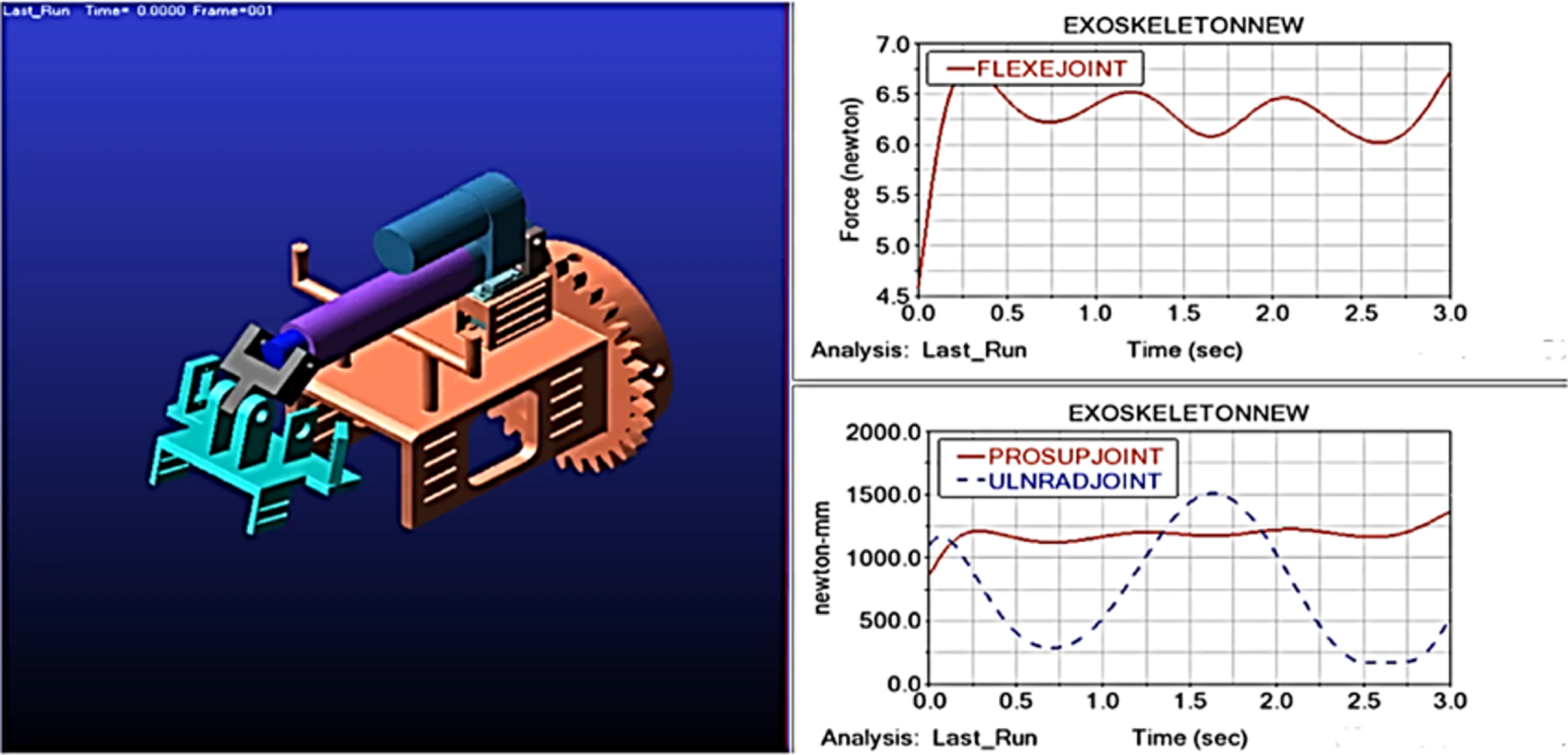
Dynamic analysis is performed by using ADAMS software. The final exoskeleton model is input to the software in Parasolid format. Then, unit setting, gravity, and density of components in the model are given as input. Individual joints are defined as per the model in the software platform. The input equations for ADAMS software are (Eq. (4–7)) which is a function for motions of the wrist-hand exoskeleton joints. The torque and force values presented in Figure 6 were analyzed using ADAMS software. These values were calculated by considering a material weight of 5 kg, the weight of the human arm which is measured using anthropometric data, and the structural weight of the robot’s components, which was obtained from the design software interface. The 5 kg material weight refers to an external load applied during exercise, intended to simulate weighted rehabilitation scenarios commonly used in physiotherapy to enhance neuromuscular recovery. The human upper arm weight was taken as 3.47 kg, based on anthropometric data for a healthy individual weighing 70 kg [Reference Tayyari and Smith35]. The structural weight of the robot’s components is 1.95 kg. This comprehensive approach ensures that all relevant interactions between the robot and the human arm are accounted for during the analysis.
Torques and forces for joint motions of the exoskeleton.

From Figure 6, the maximum torque required for the Pronation/Supination joint is τ= 1375 Nmm, and for the Ulnar/Radial joint, τ = 1500 Nmm. The Flexion/Extension joint maximum force required is, F = 6.75 N. Based on these values, relevant actuators with sufficient torque were also selected for fabrication.
5. Construction and working of exoskeleton
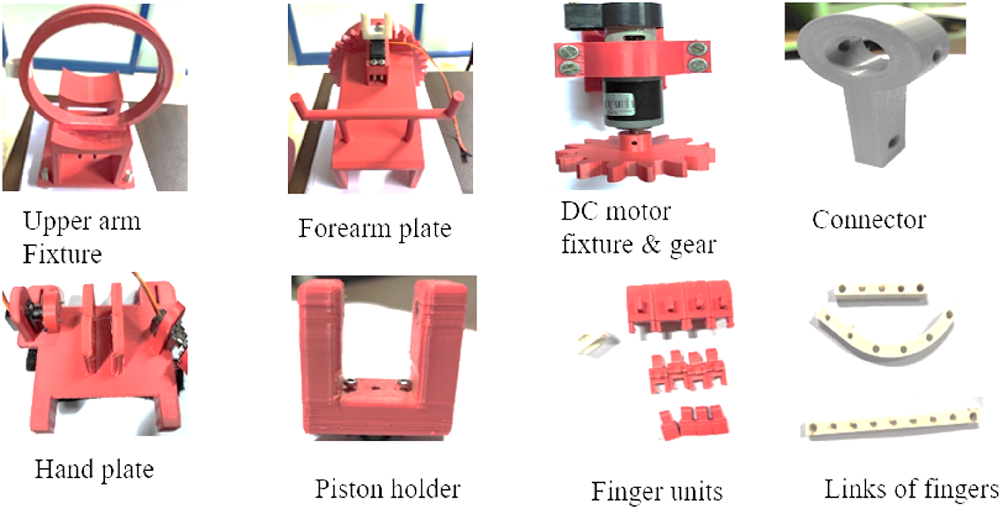
Fabrication of optimized design is done after kinematic and dynamic analysis. Each component of the wrist hand exoskeleton is printed with PLA material using a 3D printer and then integrated components along with the actuators and controllers. The final wrist hand exoskeleton components are 3D printed using PLA. The component drawing is converted to STL format and is used as input to Creality software which finally generates the code for 3D printing. The codes are fed to the Creality CR-10 Max 3D printer for final printing. The infill density for all components is set at 30% and the infill pattern used is zig-zag. Figure 7 shows all the 3D-printed components.
3D-printed components of exoskeleton.

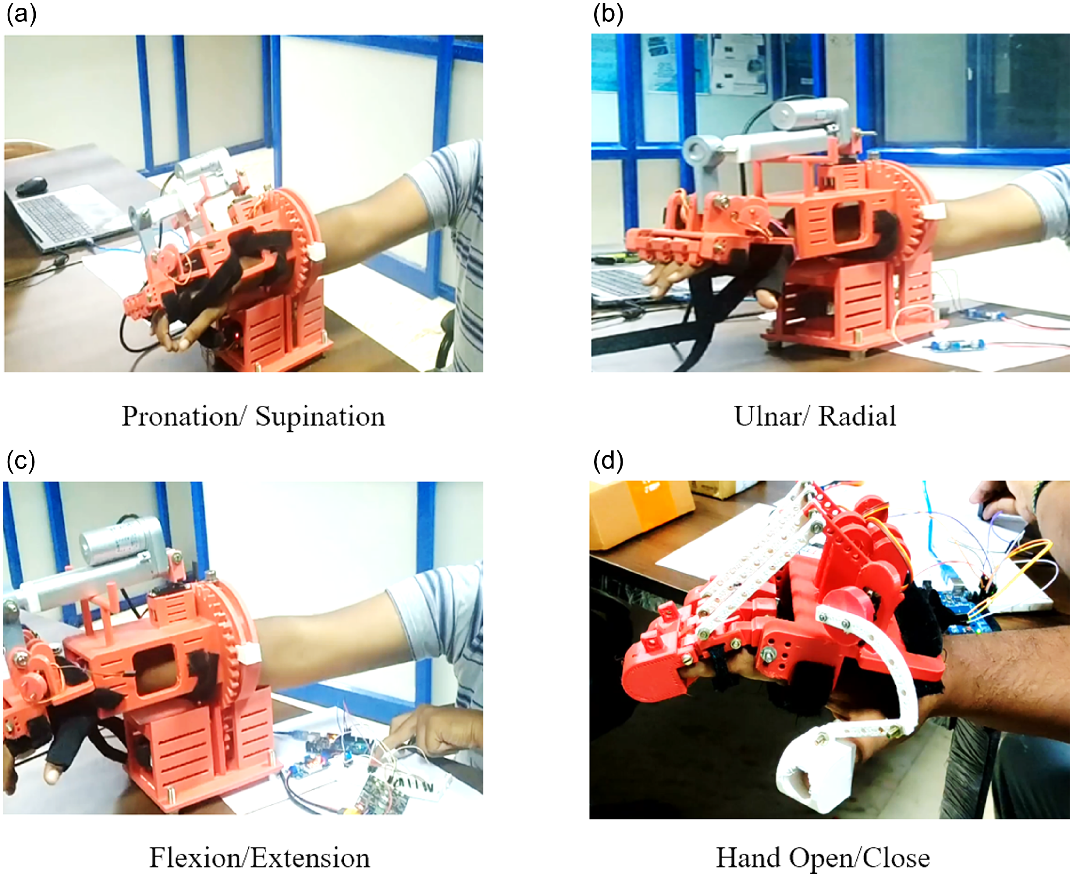
Working model positions of the exoskeleton.

Actuators are one of the main components of the exoskeleton which is responsible for getting the required motion. However, an actuator alone is not sufficient for effective working of the system, a suitable controller is also needed. The wrist hand exoskeleton is designed for mainly 3 DOF of the wrist and 1DOF of open-close arrangement for the hand fingers. The torque values obtained from the dynamic analysis are used to select suitable actuators.
The Pronation/Supination motion as shown in Figure 8(a) of the wrist is achieved by using a gear arrangement in the wrist hand exoskeleton. The corresponding joint is formed in the exoskeleton by a slot and bolt arrangement of the fixture with the forearm plate. A suitable grease lubricant is also used between these mating parts to reduce wear and tear during its operation. The gear profile is provided in the forearm end portion which is actuated with a Rhino high-precision DC motor with gear. The Ulnar/Radial motion in Figure 8(b) of the wrist is achieved by using a metal gear servo motor which is fixed in the forearm plate of the wrist hand exoskeleton. The linear actuator mounted on the metal gear servo motor is connected to the hand plate through a connector. The metal gear servo motor will move the hand along with the linear actuator. The hand is held in position using a Velcro strap attachment provided on the hand plate. The Flexion/Extension motion of the wrist is achieved by using a linear actuator as shown in Figure 8(c). The joint is formed by the connection between the linear actuator and hand plate through the connector. The open-close motion of the hand is shown in Figure 8(c) which is achieved by using two MG90S servo motors that are fixed to the hand plate. One motor which is fixed at an angle inline to the thumb is used for the motion of the thumb finger. The other one is fixed perpendicular to all other fingers and is coupled to the motor shaft. The shaft is supported at two locations with proper bearings. Two links connect the motor shafts to the fixed shafts which have the end links of all four fingers. As the motor rotates, the fingers get the required open-close actuation. The wrist-hand exoskeleton components are printed and assembled with actuators using proper connectors. The whole assembled exoskeleton is checked for individual motion in the testing face.
6. Control methods
Controlling the actuators according to the desired position is one of the major challenges in exoskeleton design. Hence, three modes of controlling techniques are tested here. The first one is a manual switch control method then a master slave method and a preliminary analysis of the EEG data-based control method.
6.1. Manual control method
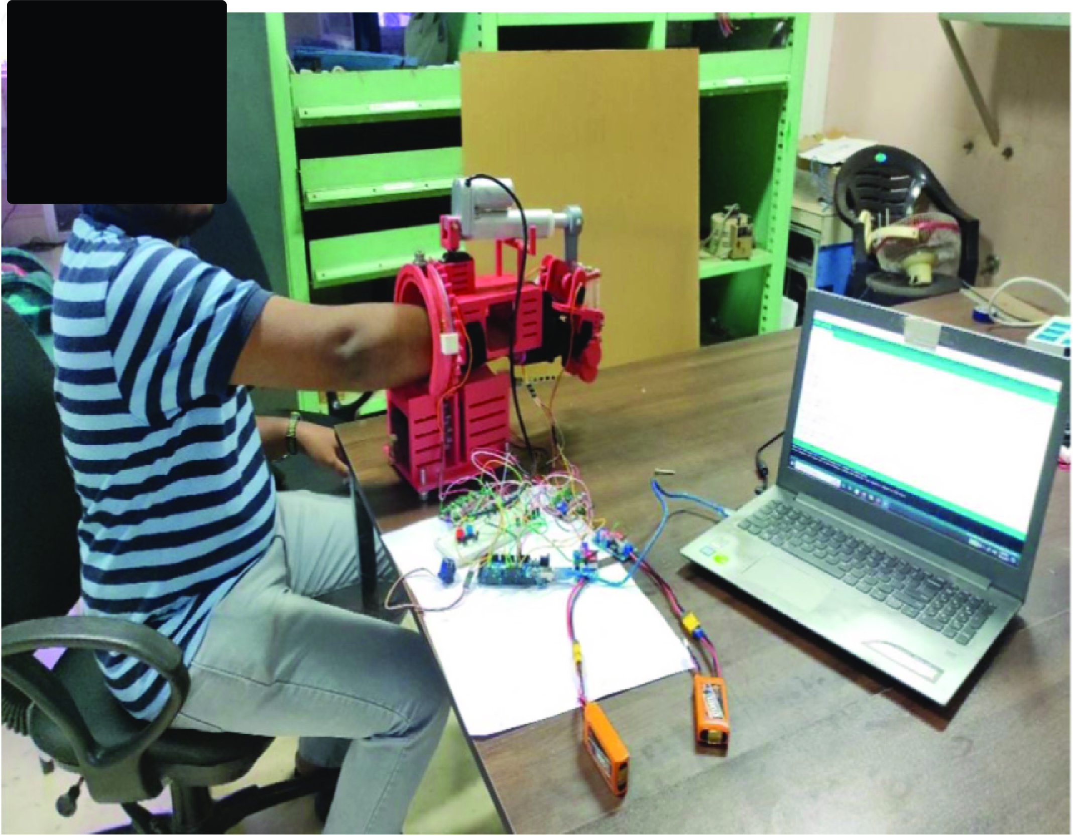
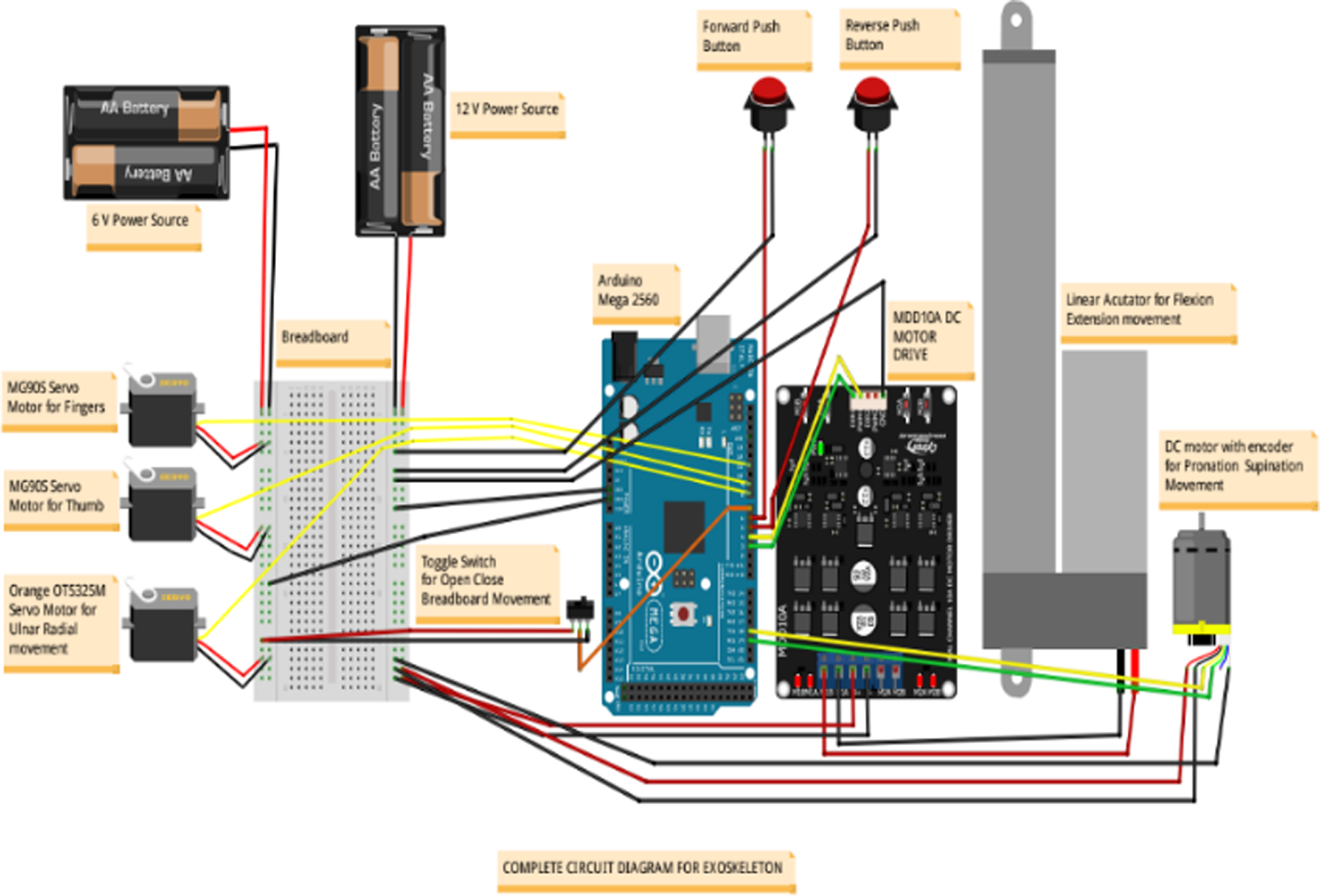
In testing the exoskeleton, the integrated motion of the exoskeleton is tested for an achievable range of motion. To demonstrate the functional use of all four degrees of freedom (DOFs) within a unified system, the setup shown in Figure 9 is tested. The Arduino Mega 2560 is the master controller in the manual switch control method, as shown in Figure 10. For manual control, two push buttons are arranged one for forward which enables wrist flexion motion, and extension motion is actuated when the second push button is pressed. The initial setup for the motion is to start from the maximum extension position and then move to the maximum flexion position. For pronation and supination motion, the Arduino code is inputted for getting from a low range of motion to a maximum range of motion and checked its feasibility. For ulnar/radial motion, a linear actuator mounted on a metal gear servo motor is connected to the hand plate via a connector. The metal gear servo motor moves the hand along with the linear actuator. The hand is secured in position using a Velcro strap attached to the hand plate. An Arduino is programmed to generate the required motion pattern, and the code is generated to get the range of motion up to the physical limit.
Integrated manual control.

Circuit diagrams for manual control.

A push-button setup is used for the individual control of all four actuators. The power source used is two 11.1 V 3-cell battery packs. Jumper wire along with a breadboard arrangement is also selected for power distribution from the power source. Two types of switches push-button type and toggle type are also selected based on the requirement for proper power supply control. The power source selection is based on the hours of operation requirement and power input requirement of actuators and controllers.
6.2. Master slave
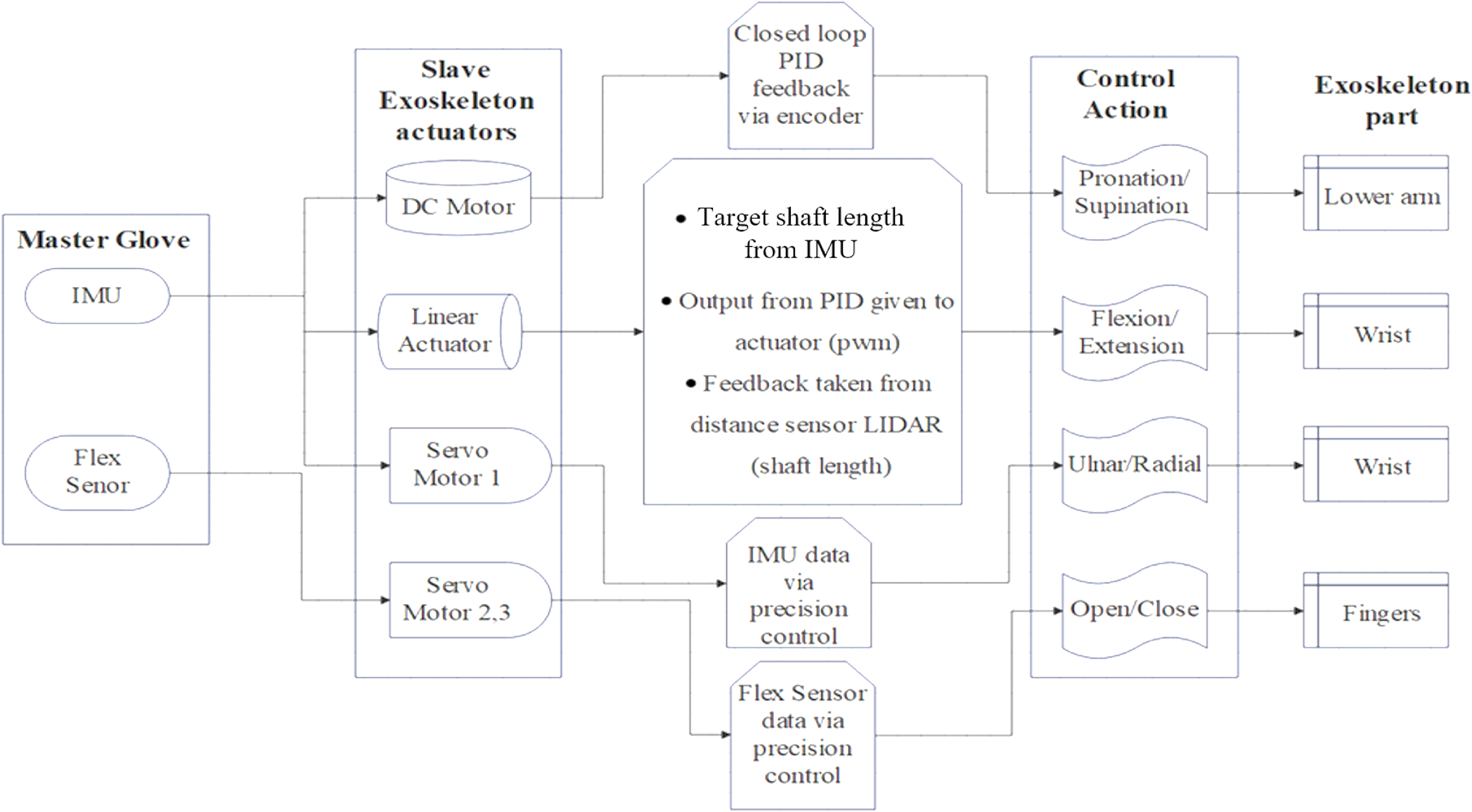
Exoskeleton systems frequently employ the master-slave control approach, which enables users to direct the exoskeleton’s motion with their physical motions or that of caretakers. The master-slave mechanism is used in such a way that the master glove will be mounted on the Physiotherapist or the helper’s hand. This glove is attached with IMU and flex sensors. The user’s motions are recorded by these sensors, including joint angles and other pertinent information. To create control commands for the exoskeleton, the data from various sensors are analyzed. The exoskeleton itself, which is worn or wrapped around the limbs by the user, is referred to as the slave component. Actuators, sensors, and control systems make up this set of devices. To support or improve the user’s motions, the actuators deliver the appropriate forces and torques. The sensors in the slave component keep track of the joint angles, forces, and velocities of the exoskeleton, by using a Flex sensor and IMU module as the reference by the master for attaining specific positions in the exoskeleton(slave). By mapping human motions recorded by the master component to equivalent exoskeleton movements, the master-slave control system operates. The control algorithm analyzes the master component’s sensory input and produces control signals to actuate the slave component as necessary. Figure 11 shows the block diagram details of the working of the exoskeleton with the master-slave control technique.
Block diagram for master-slave control.

A flex sensor is connected with a circuit in series to the node MCU and then to the laptop (Wi-Fi/USB) and the Arduino board. These sensors are placed on the finger joint of the master to obtain the desired position. An IMU unit which is mounted on the top of the Wrist of the master will help to align the angular positions of the wrist motion. These are connected to the Laptop using Wi-Fi (ESP8266) and send the data using ROS Serial TCP. The data from the computer will be sent to the Arduino to actuate the position of the corresponding actuator. All the positions will be identified in XYZ directions, and the bend angle will be communicated by the flex sensor. These data will be sent to Arduino by using the ROS serial module. These are the target angles sent from the Master Glove.
Open and close of hand as well as adduction abduction are controlled using servos. Servo motor angles will be directly sent to the Arduino. The current angle in the DC motor will be found using the encoder data. And the target angles will be received from IMU. Using the target angle and current angle the output error is found out as PWM using PID control. This data is sent back to Arduino for controlling the DC motor. A LIDAR module is used to measure the distance of the linear actuator which enables flexion-extension of the wrist. The target angle will be received from the IMU module. The current angle is mapped from the displacement sensor. Error is evaluated by taking the difference between these. This error is inputted to the PID controller and the output determines the speed and direction of the actuator.
6.3. EEG dataset-based control
Biomedical signals of EEG allow us to measure the potential difference generated in the scalp. These signals represent neuronal activities corresponding to each area of the brain. EEG data are used to determine the intentionality of the subject when performing motor and imaginary motor tasks. Birth defects, cerebrovascular accidents, trauma, and others are the targeted community to get benefit out of the intentionality detection.
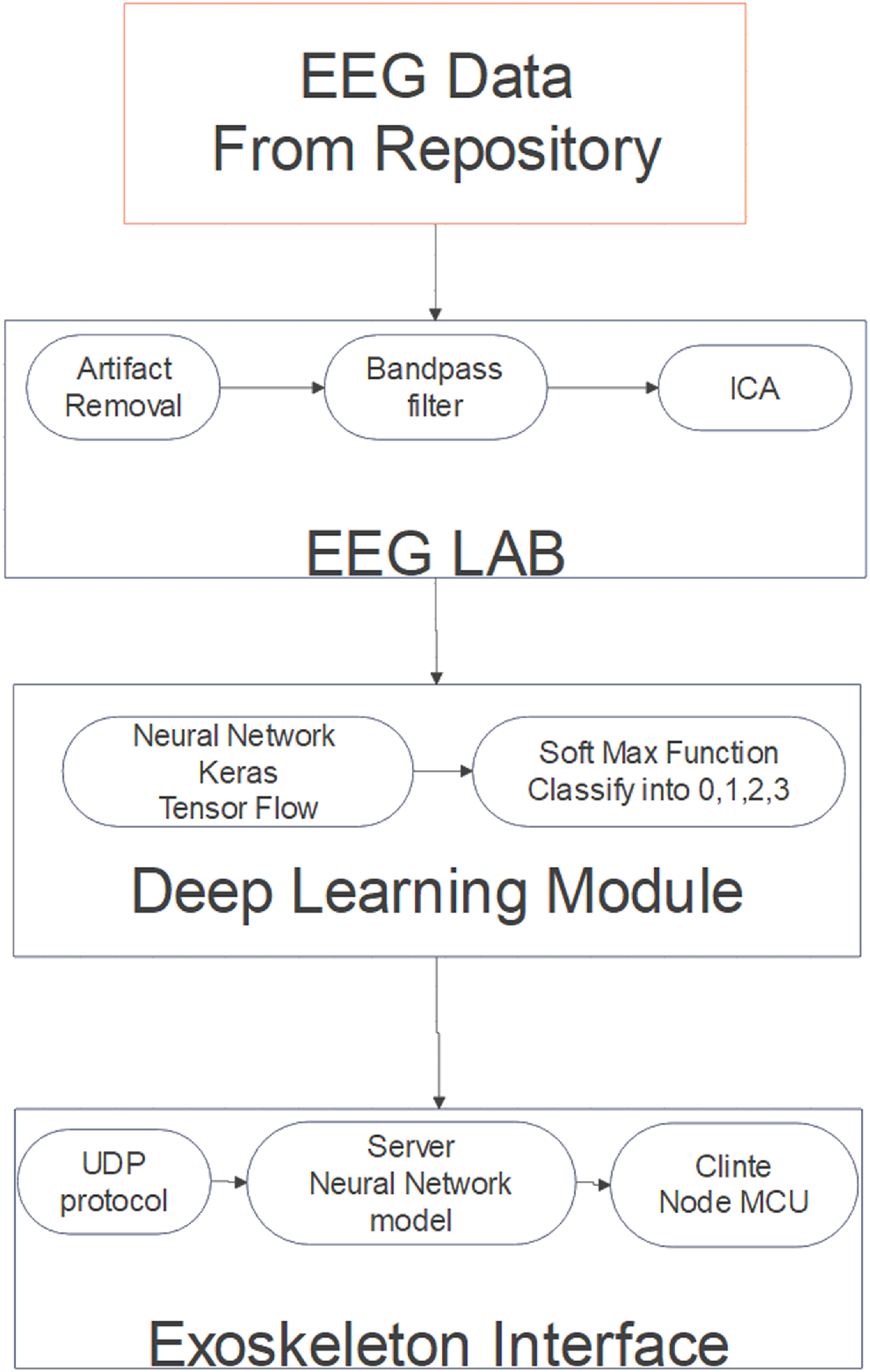
In this work, a dataset from the repository named Physionet is used for testing. This dataset consists of 1500 EEG recordings of 2 minutes for different limb movements of 109 volunteers. The dataset is recorded using the BCI2000 system with the help of a 64-channel EEG. Each participant completed 14 experimental runs, including two baseline runs of one minute each (one with eyes open and one with eyes closed) and three runs of two minutes each of the four activities. More details about the procedure and capturing methods are mentioned in this research paper [Reference Goldberger, Amaral, Glass, Hausdorff, Ivanov, Mark, Mietus, Moody, Peng and Stanley36, Reference Schalk, Mcfarland, Hinterberger, Birbaumer and Wolpaw37]. The flow of work is shown in Figure 12.
Block diagram for EEG dataset-based control model.

The data from the EEG repository are processed initially in the EEG lab with a MATLAB plugin. Using a bandpass filter, the required range of signals was filtered (8–30 Hz). The most important brain oscillations in SMR-based BCIs may be found in the alpha (8–13 Hz) and beta (13–30 Hz) frequency ranges. The SMR develops a distinct mode as a result of limb movement imagining. These modes are part of both event-related synchronization and event-related desynchronization in SMR. In contrast to prior ESI investigations, which chose a region of interest by locating specific gyral landmarks on subject-specific cortical models, the motor cortex is segmented into 10 sections. BCIs enable novel forms of human-machine interaction for both impaired and healthy users, such as music creation and game control, and not just have a good influence on users with impairments in terms of life quality and communication with their surroundings. The above data were taken as reference and given as the corresponding signals for the opening and closing of hands. Independent component analysis is a method for transforming a set of mixed signals into a set of independent components. Usually, ocular muscle, electrocardiographic, and power line artifacts are traced with the use of this method.
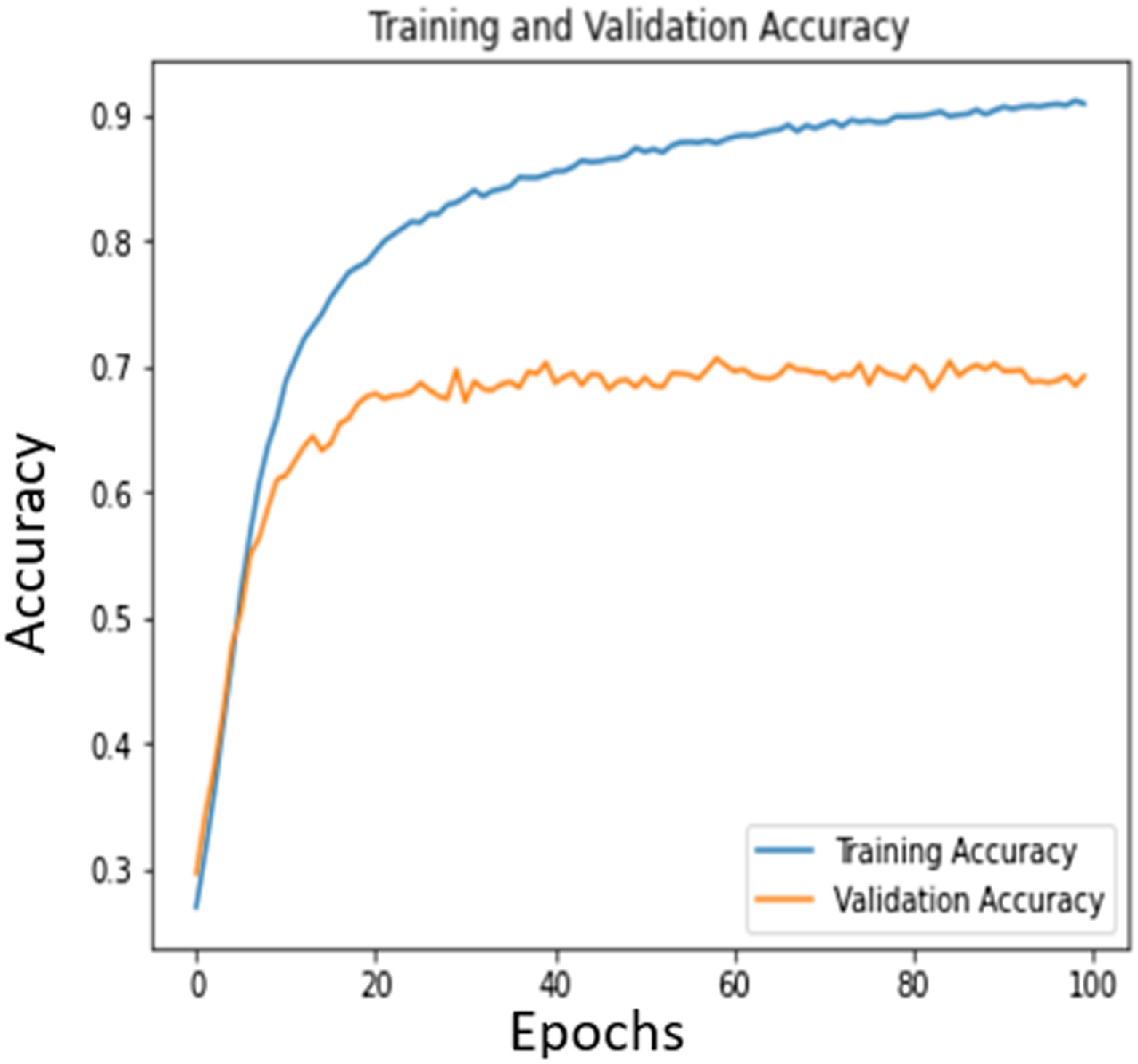
Hereafter the data are classified using Deep learning techniques. The dataset was initially in .edf format and then it is converted to .csv format. The neural network model is run in Keras and TensorFlow. Based on a Morlet wavelet, characteristics were retrieved from the scout time series. As can be seen, this wavelet was first created at a central frequency where the full width at half-maximum (FWHM) of its Gaussian kernel determines its temporal resolution. The FWHM of the Gaussian kernel was selected to be 3s, and the center frequency was set at 1 Hz. The wavelet’s length was adjusted for the remaining frequencies to better capture the oscillatory activity’s varied components. At 0.5 Hz intervals, the wavelet coefficient was determined and then convolved using the chosen waveforms. The Gaussian-adjusted exponential complex-valued wavelet known as the Morlet wavelet, which lacks orthogonality, features an imaginary component called i. Feature extraction is performed using power spectral density (PSD), as determining motor intention within the β frequency range (16–24 Hz) commonly relies on PSD-based features. Using the softmax function, the limb movements are further classified into 0,1,2,3 according to the movement. Out of the total data, 90% is used for training and 10% is used for testing. Figure 13 shows the training and validation accuracy curves.
Training and validation accuracy of the dataset.

The model, which has a six-layer convolution network with two max-pooling layers and three fully linked layers, is based on the Deep ConvNet design suggested by Schirrmeister et al. [Reference Schirrmeister, Springenberg, Fiederer, Glasstetter, Eggensperger, Tangermann, Hutter, Burgard and Ball38]. Based on the values given by Krizhevsky et al. [Reference Krizhevsky, Sutskever and Hinton39], the size and number of kernels were empirically calculated. In the beginning, a Deep ConvNet architecture with the PhysioNet database, which consisted of four convolutional layers, four max-pooling layers, and one fully connected layer was used. Two max-pooling layers were used instead of four empirically to better suit the size of our data by taking into account the pooling kernel size (a 2D kernel such as 2 × 2 in our work versus a 1D kernel such as 3 × 1 in Deep ConvNet architecture) and stride size (stride both two for height and width in our work versus stride one for height and three for width in Deep ConvNet architecture). Additionally, various convolutional and fully connected layer counts have been experimented. Higher accuracy on the test set was produced by adding more convolutional layers. More than six convolutional layers barely caused the accuracy to stop increasing. The best-performing layers in the trials were the three completely linked layers from our study and the six levels of convolution operation. Additionally, in this section, the proposed baseline model was assessed using the database, and also it is contrasted with other models while using several overfitting prevention techniques. These 0,1,2,3 are transferred to the exoskeleton utilizing a server-client interface which allows the individual motors to produce corresponding actions.
7. Discussion
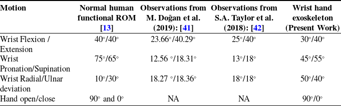
The research aims to develop a wrist-hand rehabilitation exoskeleton, primarily aimed to use for people with wrist disabilities. The design and development of hand exoskeleton robots for active rehabilitation present a promising solution for improving hand and wrist function in individuals with neurological impairments [Reference Sandoval-Gonzalez, Jacinto-Villegas, Herrera-Aguilar, Portillo-Rodiguez, Tripicchio, Hernandez-Ramos, Flores-Cuautle and Avizzano40]. The kinematic and dynamic analysis of exoskeletons examines joint angles, range of motion, torque transmission, and actuation strategies. The range of motion ROM is measured and compared with different observations from research articles.
Table V compares the ROM of normal human wrist and hand movements with different observations. The present work’s exoskeleton closely mimics natural wrist flexion/extension and hand open/close movements. It also offers the extra feature of full hand-opening functionality, which is absent in most wrist exoskeletons. The comparison of wrist and hand motion ranges across different studies and the present work on a wrist-hand exoskeleton reveals notable variations. In terms of wrist flexion and extension, the normal human functional range of motion (ROM) is 40°/40°, while M. Doğan et al. (2019) observed 23.66°/40.29°, and S.A. Taylor et al. (2018) reported 25°/40°. The present exoskeleton design achieves 30°/40°, indicating a closer approximation to normal human ROM compared to the previous studies. For wrist pronation and supination, the normal ROM is 75°/65°, but the studies by Doğan et al. and Taylor et al. reported significantly lower values of 12.56°/18.31° and 13°/18°, respectively. The exoskeleton improves upon these values at 45°/55°, though it still falls short of the normal ROM. In wrist radial and ulnar deviation, the normal ROM is 10°/30°, while both studies reported nearly equal values of around 18°/18°. The exoskeleton, however, achieves a higher range of 50°/40°, surpassing the normal ROM. Lastly, for hand open/close motion, the normal ROM is 90°/0°, and while the studies did not provide data, the exoskeleton matches the normal ROM perfectly at 90°/0°. Overall, the exoskeleton demonstrates advancements in replicating or exceeding human ROM in certain motions, though there is room for improvement in others, particularly pronation and supination.
Motion comparison.

The implementation of novel control strategies in this study enhances the functionality and adaptability of the exoskeleton system, demonstrating its potential for diverse rehabilitation needs. The manual control mode offers flexibility by enabling user-defined or range-based movements based on pre-inputted data through an intuitive interface. This provides patients with personalized motion control that aligns with their specific rehabilitation requirements. The master-slave control approach further enriches the system by allowing the exoskeleton to mirror the movements demonstrated by a physiotherapist or caregiver, fostering an interactive and guided rehabilitation process. Additionally, the exploration of EEG dataset-based control strategies underscores the potential for developing intention-driven systems in the future. While this study primarily focused on analyzing the hand open-close movement due to the limitations of the available EEG datasets, it successfully demonstrates the feasibility of incorporating neural data into the control framework. This approach not only validates the integration of EEG datasets for functional control but also opens avenues for expanding intention-based systems to address other degrees of freedom.
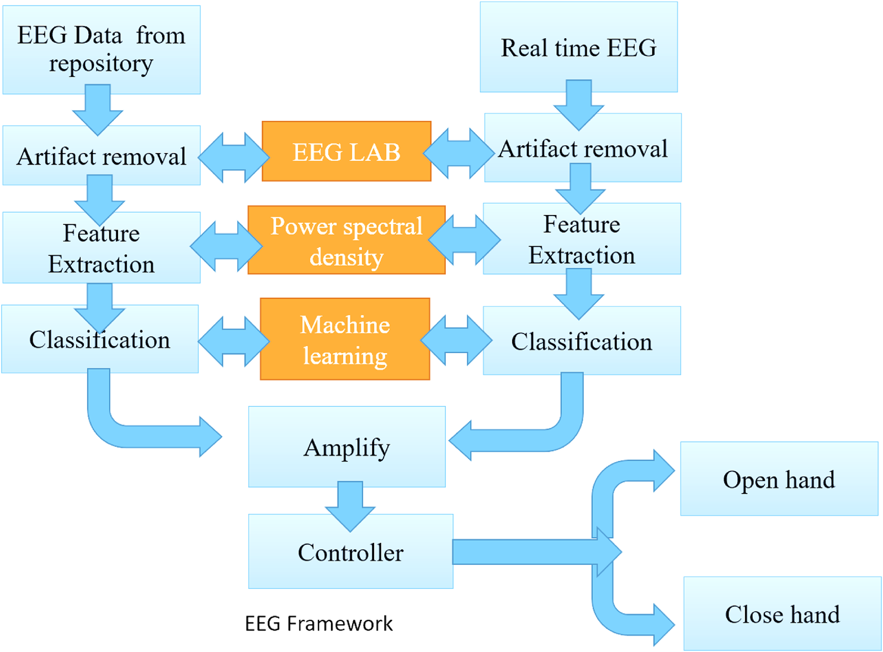
Figure 14 illustrates the recommended method of real-time EEG implementation technique. Comparing and calibrating the EEG data from a repository and real-time EEG will accurately actuate the required angle. Both undergo artifact removal to filter out unwanted signals. The feature extraction is performed to identify key patterns in the EEG data. The extracted features are processed through EEG LAB, where power spectral density and machine learning algorithms are applied for further analysis. The classified data are then amplified and sent to a controller, which interprets the signals to either open or close the hand, depending on the detected brain signals. This system allows real-time control of hand movements based on brain activity, making it ideal for users with severe motor impairments. Overall, the control strategies implemented in this study highlight the system’s versatility, adaptability, and potential for further advancements in rehabilitation technology.
Flow diagram of the EEG-based dataset.

8. Limitations and future scope
It is important to acknowledge certain limitations that warrant further investigation. The design is currently limited to wrist and hand movements, excluding actuation of the shoulder and elbow joints, which restricts its application in comprehensive upper-limb rehabilitation. However, future iterations aim to integrate shoulder and elbow actuation as modular features to enable complete upper-limb support. Due to the unavailability of a specific, task-oriented EEG dataset, the EEG-based control has been limited to basic hand movements, without extending to wrist movement control. The absence of real-time EEG-based control testing restricts the evaluation of the system’s immediate applicability in dynamic settings. Real-world EEG signals are influenced by factors such as noise, signal drift, and inter-subject variability, which cannot be fully simulated offline [Reference Doğan, Koçak, Onursal Kılınç, Ayvat, Sütçü, Ayvat, Kılınç, Ünver and Aksu Yıldırım41]. Therefore, the future work will focus on real-time validation of the system, including latency benchmarking [Reference Taylor, Kedgley, Humphries and Shaheen42], adaptive control mechanisms [Reference Bomfim, Monteiro and Lima43], and robustness testing under varying user conditions. These efforts aim to ensure reliable and responsive performance during live BCI-mediated exoskeleton control, bridging the gap between laboratory validation and clinical application. Additionally, the generalizability of the exoskeleton design across diverse user populations, the long-term durability of the 3D-printed PLA structure, and the sustained effectiveness of the proposed control techniques in extended rehabilitation scenarios remain open areas for future research.
9. Conclusion
This paper describes the design, construction, and operation of a unique wrist and hand exoskeleton. It emphasized the necessity for an exoskeleton that can offer support and enhance the wrist hand’s ROM and usefulness. To create an appropriate exoskeleton concept, brainstorming and ideation were used throughout the conceptual design process. Based on the criteria, several design concepts were developed and assessed. The concept screening and scoring procedure assisted in determining which design concept was most promising. The performance of the exoskeleton design was heavily influenced by the kinematic and dynamic studies. By examining the joint kinematics and dynamics it is easy to determine the exoskeleton’s ROM, torque needs, and potential restrictions.
The exoskeleton’s structural soundness and ergonomic fit were guaranteed during the construction phase. Three control strategies such as manual control, master-slave control, and control based on EEG datasets were investigated. While master-slave control used sensor inputs to map the user’s motions to the exoskeleton, manual control allowed users to operate the exoskeleton directly through physical input. The EEG dataset-based control utilized brain signals to understand the user’s intent and adjust the exoskeleton in accordance, using the pre-captured dataset. A Deep ConvNet architecture was deployed for data classification. A new method for implementing real-time EEG data is also proposed in comparison with a dataset-based method. Users with differing ROMs had a variety of alternative control methods. While the various control techniques provide flexibility and adaptation dependent on user need, the construction process employing PLA provides durability and customization. The control algorithms may be improved further, and machine learning methods and comprehensive user trials may be carried out to evaluate the performance of the exoskeleton in actual usage. The user experience and engagement with the exoskeleton may also be improved by investigating the integration of sensory feedback systems. The present work’s wrist-hand exoskeleton provides a good balance of wrist motion, closely mimicking natural flexion/extension and hand open/close ROM. The current research can be improved by clinical trials, which are essential for establishing the need for robotic assistive devices and by implementing real-time EEG signals.
Author contributions
MM, KS, and APS proposed the research project; MM conducted the review and wrote the first draft; KS and MM designed the novel wrist hand exoskeleton. AS and VP helped with control techniques. APS provided advice, correction, and supervision.
Financial support
No financial support
Competing interests
The authors declare no conflicts of interest.
Ethical considerations
No ethical issue with this paper.