I. INTRODUCTION
In recent years, much attention has been paid to the synthesis and investigation of nanostructured magnetic materials because of their excellent physical, catalytic, magnetic properties, and their crucial applications in diverse fields, including microwave absorbing,Reference Kuanr, Veerakumar, Lingam, Mishra, Kuanr, Camley and Celinski1–Reference Liu, Li, Geng, Cui, Yang, Xie, Kang and Zhang3 high-frequency soft magnetic applications,Reference Liu, Geng, Choi, Kim and Zhang4–Reference Zhao, Zhang and Xiao6 magnetic catalysts,Reference Lee, Lee, Youn, Na, Yu, Kim, Lee, Koo, Kwak, Park, Chang, Hwang, Park, Kim and Hyeon7 biomedical treatments and analysis,Reference Gupta, Naregalkar, Vaidya and Gupta8 magnetic fluids,Reference Xia, Wang, Tian, Chen, Du, Zhang, He and Sun9 magnetic photonic crystals,Reference Figotin and Vitebskiy10 high-density magnetic storage media,Reference Sun, Murray, Weller, Folks and Moser11, Reference Luo, Du and Misra12 etc. In particular, the rapid developments of wireless communication devices require miniature magnetic components, such as inductors and transformers, to be operated at high frequency, which required that the magnetic materials should have large saturation magnetization (M s), high permeability (μ′), and low energy lossesReference Tang, Zhong, Jiang, Han, Zou and Du13 for high-frequency applications. Soft magnetic ferrites because of their high permeabilities and low energy losses are the traditional materials in these applications. However, the high-frequency performance of these ferrites is limited by Snoek’s lawReference Osipov, Iakubov, Lagarkov, Maklakov, Petrov, Rozanov and Ryzhikov14 due to their lower saturation magnetization (M s). Metal magnetic nanoparticles, such as iron, cobalt, nickel and alloys, are potential substitutes for ferrites because of their high saturation magnetizations and high Curie temperatures. Among these, Fe–Ni alloy, especially FeNi3, has great prospect for electromagnetic device applications with both high saturation magnetization and low coercivity.Reference Zhao, Ni, Kruczynski, Zhang and Xiao15 The nanometric Fe–Ni alloys have been produced by various methods, such as mechanical alloying,Reference Jartych, Zurawicz, Oleszak and Pekala16, Reference Lima, Drago, Fichtner and Domingues17 decomposition of carbonyl compounds,Reference Kaloshkin, Tcherdyntsev, Tomilin, Baldokhin and Shelekhov18 electrodeposition,Reference Hong, Rheem, Lai, Cwiertny, Walker and Myung19, Reference Freeland, Grigorov and Walker20 inert-gas condensation method,Reference Djekoun, Boudinar, Chebli, Otmani, Benabdeslem, Bouzabata and Greneche21 sol–gel synthesis,Reference Tang, Zhong, Jiang, Han, Zou and Du13 and chemical reduction process.Reference Lima, Drago, de Lima and Fichtner22–Reference Li, Li, Wang, Li and Qian29 Among these routes, chemical reduction in aqueous solution can be easily performed and has advantages for lower cost, lower temperature, and less time. The reducing agents, such as polyol,Reference Qin, Pei, Ren, Shimada, Endo, Yamaguchi, Okamoto and Kitakami23 NaBH4,Reference Lu, Liang and Zhang24 hypophosphite,Reference Moustafa and Daoush25 and hydrazine hydrate (N2H4·H2O),Reference Lima, Drago, de Lima and Fichtner22, Reference Lima, Drago, Bolsoni and Fichtner26, Reference Wang, Li, Kou and Zhang27 are commonly used. However, polyol process should be performed at temperature higher than about 100 °C, and NaBH4 reduction may produce Fe2B during reaction.Reference Lu, Liang and Zhang24 Hydrazine hydrate is a moderate reducing agent with low cost and has been proven to be good alternative for producing metallic particles. Spherical FexNi1−x alloys (x = 0.15, 0.20, 0.22, 0.25, 0.30, 0.50, and 0.65) have formed with the reduction of N2H4·H2O under alkaline condition.Reference Lima, Drago, de Lima and Fichtner22, Reference Lima, Drago, Bolsoni and Fichtner26 The spherical FeNi3 alloy nanoparticles have been synthesized using hydrazine hydrate as reducing agent at room temperature.Reference Lu, Liang and Zhang24 Sheetlike FeNi3 nanoparticles have been produced using hydrazine hydrate as a reductant at 55 °C moderate temperature under ultrasonic irradiation.Reference Wang, Li, Kou and Zhang27 And FeNi3 alloy nanoplatelets were prepared using hydrazine hydrate as a reductant and sodium dodecyl sulfate as a surfactant by hydrothermal reduction at 180 °C.Reference Liao, Tannenbaum and Wang28 Although the mechanism of the shape control has been suggested, the transformation from nanosphere to nanoplatelets was not detailed. In the present work, the FeNi3 platelet nanoparticles were obtained by hydrazine reducing route at room temperature under ultrasonic irradiation. The formation of FeNi3 nanoparticles and the possible transformation from spherical to platelet was speculated. Also, M s and coercive force (H c), as well as the complex permeability μ dependency on frequency in the range of 1.0 MHz–1.0 GHz were investigated.
II. EXPERIMENTAL PROCEDURE
A. Materials
All chemicals used in this experiment were of analytical grade and used without further purification. Nickel chloride hexahydrate (NiCl2·6H2O) and sodium hydroxide (NaOH) were purchased from Beijing Chemical Works (Beijing, China). Iron chloride tetrahydrate (FeCl2·4H2O) and hydrazine hydrate (N2H4·H2O) with 80 wt% content were received from Fuchen Chemical Reagent Ltd., Tianjin, China.
B. Synthesis of Fe–Ni nanoparticles
The Fe–Ni nanoparticles were produced by hydrazine aqueous reduction method. Specifically, 0.01 mol of FeCl2·4H2O and 0.03 mol of NiCl2·6H2O (the molar ratio of Fe2+ to Ni2+ was 1:3) were dissolved in 50 mL deionized water together, to form a green transparent solution (a) with pH of 2.0, detected by Mettler Toledo (Urdorf, Switzerland) pH instrument. N2H4·H2O (0.16 mol/L) and NaOH (0.25–0.75 mol/L) were mixed as transparent solution (b) with pH of 11.5–13.0. Solution (b) was dripped into solution (a) by three simple processes at ambient temperature of 20 °C as followed: (i) directly dripping solution (b) into solution (a) without stirring to form a mixture marked for sample 1; (ii) dripping solution (b) into solution (a) in the rate of 0.12 mL per s controlled by a peristaltic pump (BT100-2J, Baoding Longer Precision Pump Co., Baoding City, Hebei, China) under mechanical stirring for 30 min, signed as sample 2; (iii) dripping solution (b) into solution (a) as the same rate as sample 2 under 40 kHz ultrasound irradiation, produced by a KQ-100E ultrasonic instrument (Kun Shan Ultrasonic Instrument Co., Ltd, Kunshan City, Jiangsu, China) for sample 3. After mixing, pH of the mixture became 10.5–12.5 according to the concentration of NaOH in solution (b). After a little while, black precipitates were produced and simultaneously the gas bubbled from the solution. The reaction continued for 24 h, and the black precipitates were filtered through acetate cellulose membrane filter with a pore size of 0.2 μm and washed thoroughly by deionized water, until the pH value of filtrate was about 7. The products were dried at 60 °C in a vacuum oven for 6 h and preserved in a desiccator for characterization.
C. Characterization
The crystallographic structure of the as-prepared samples were characterized by x-ray diffraction (XRD), (XRD-7000 x-ray diffractometer from Shimadzu Co., Kyoto, Japan) with CuKα radiation (λ = 1.5405Å). The morphologies of the samples were analyzed by field emission scanning electron microscopy (Hitachi S-4300, Hitachi High Technologies, Hitachi Co., Hitachi, Japan), with 15 kV accelerating voltage. The magnetic properties were measured by vibrating sample magnetometer model (Lake Shore 7410, Lake Shore Cryotronics, Inc., Westerville, OH). Complex permeability spectra of the samples were measured with an impedance analyzer (16454A and 4396B, Agilent Technology, Inc., Santa Clara, CA) in the range of 1.0 MHz to 1.0 GHz. Prior to measurement, the FeNi3 particles were firstly mixed with 10.0 vol.% of solid paraffin (C13–18 linear alkane, provided by Beijing Yanshan Petrochem. Co., Beijing, China) and heated at 50 °C to form a black slurry. Then, the slurry was transformed into a ring mold with 18 mm in outer diameter, 3 mm in inner diameter, and 2–3 mm of thickness, under pressure of 1.0 MPa. After 5 min, the plate ring of the sample was taken out for measurement.
III. RESULTS AND DISCUSSION
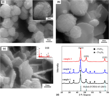
Spherical FeNi3 alloy particles were obtained when the molar ratio of Fe2+ to Ni2+ was 25:75.Reference Lu, Liang and Zhang24 Therefore, the molar ratio of Fe2+ to Ni2+ was fixed as 1:3 in this work. To investigate the effects of ultrasound on the crystal growth of FeNi3 alloy particles, three experiments were performed to explore the formation process with pH of the mixture fixed as 12.5. In first experiment, the reaction took place by directly mixing the reactant solution without any stirring. After 30 min, spherical particles of sample 1 were obtained, as shown in Fig. 1(a). The diameter of the particles was 50–70 nm. In the second experiment, sample 2 was synthesized by stirring for 30 min instead of ultrasound. The scanning electron microscopy (SEM) image in Fig. 1(b) showed that both spherical and platelet particles were obtained, indicating that the shapes of the particles transformed from spherical to platelet. The diameter of the plates was from 30 to 80 nm. Some edge-curled platelets marked in Fig. 1(b) were due to its high surface energy.Reference Li, Li, Wang, Li and Qian29 Relatively uniform platelet particles of sample 3 were obtained under ultrasound irradiation. The SEM images shown in Fig. 1(c) indicated the complete transformation from spherical to platelet under the strong driving force resulting from the ultrasound irradiation. The platelets were 102 nm in diameter, with a thickness of about 14 nm.
Scanning electron microscopy (SEM) images of (a) sample 1, (b) sample 2, (c) sample 3, with 0.16mol/L of N2H4·H2O at pH of 12.5, and (d) is the corresponding x-ray diffraction (XRD) patterns of the samples. The JCPDS card is 65-3244 for FeNi3 and 65-3107 for Fe3O4.

The corresponding XRD patterns of the particles are shown in Fig. 1(d), which shows that all of the patterns exhibit diffraction peaks at 2θ of 44.16°, 51.46°, and 75.78°, ascribing to the crystal planes of (111), (200), and (220), respectively, of the crystalline face-centered cubic (fcc) FeNi3 alloy (JCPDS 65-3244). However, the XRD patterns of sample 1 and sample 2 in Fig. 1(d) showed four other diffraction peaks at 2θ of 30.16°, 35.7°, 57.1°, 62.98°, attributed to 220, 311, 511, 440 crystalline facets of Fe3O4. This indicates that Fe3O4 was partially formed during the reaction under direct mixing and moderate stirring. The XRD pattern of sample 3 with only platelet particles and a typical FeNi3 XRD pattern indicates that the FeNi3 alloy nanoparticles under ultrasound irradiation were relatively pure. Comparing with the standard pattern of the pure nickel (JCPDS 65-2865), the [111] peak of the as-synthesized Ni–Fe alloy particles shifted to a lower angle (ca. 0.10°, see supporting Fig. S1). The lattice constant, a, calculated from the [111] peak was 3.549 Å, which was slightly larger than that of fcc Ni (a) 3.524 Å, JCPDS 65-2865). This implies that Fe atoms are incorporated into the fcc Ni lattice, leading to the enlargement of the interplanar spacing because the radius of Fe atoms (1.26 Å) is larger than that of Ni atoms (1.24 Å). The energy-dispersive x-ray spectroscopy analyses measured on SEM of sample 3 shown in inset of Fig. 1(c) indicated that the as-prepared product under ultrasound irradiation exhibited both Ni and Fe peaks. The atomic ratio of nickel to iron was measured to be 75.64:24.36, which was very close to the initial set ratio of Fe2+:Ni2+ = 1:3. This proved that Ni2+ and Fe2+ salts were almost reduced to zerovalent metals and formed FeNi3 alloy, in accordance with the result of XRD.
It is known that the electromotance of oxidation reaction from Fe2+ to Fe3+ is 0.66 V, higher than that of reduction reaction from Fe2+ to Fe (0.283 V). So, Fe2+ is more likely to be oxidized into Fe3+ and is difficult to be reduced into Fe directly in alkali aqueous solution unless favored by some special measures, such as ultrasonic, high pressure, etc. But for Ni2+, the electromotance of reduction reaction from Ni2+ to Ni is 0.47 V. Thus, Ni2+ can be easily reduced into Ni in alkali condition.Reference Lu, Liang and Zhang24 When Fe2+ and Ni2+ were treated with hydrazine hydrate in alkalescent medium, Fe(OH)2 was easily formed under the basic condition, and the formed Ni would in turn reduce Fe(OH)2 to Fe particles as surface catalyst.Reference Su, Zheng, Yang, Zhu and Pan30 In this work, the 3:1 molar ratio of Ni2+ to Fe2+ in solution would not only facilitate the reduction of Fe2+ to Fe and benefit the formation of FeNi3 alloy particles as reaction (1)Reference Lu, Liang and Zhang24 but also hinder oxidization of Fe during the process of hydrazine reduction for its higher stability than Fe.

Since the dissolved oxygen existed in the aqueous solution, partial Fe (II) would be oxidized, resulting in formation of Fe3O4 by reaction (2) and (3).Reference Shao, Dai and Ma31


Ultrasonic irradiation can provide transient high temperatures and high pressures in solution under acoustic fields.Reference Dhas and Gedanken32 Bubbles in the solution would be implosively collapsed during the sonochemical cavity collapse by acoustic cavitation, favoring the removal of dissolved oxygen from the solution. Furthermore, when the redox solution was irradiated with ultrasound, the sonolysis of water (i.e., water molecules decomposed under ultrasound) may generate H˙ and OH˙ radicals as reaction (4),Reference Okitsu, Ashokkumar and Grieser33 and significantly promote the reduction rate, and improve formation of relative pure phase of FeNi3 crystalline.

Furthermore, the alternating expansive and compressive acoustic waves created bubbles (i.e., cavities) and made the bubbles oscillate. These oscillating bubbles may grow and accumulate ultrasonic energy effectively. Under the right conditions, a bubble can overgrow and then collapse, inducing release of concentrated energy in the bubble within a very short time. Ultrasound irradiation can also enhance the Ostwald ripening processes (i.e., ultrasonic irradiation accelerates solid particles to high velocities and drive them together to induce nanoparticles merging at the point of interparticle collision) via acoustic cavitation–induced turbulenceReference Zhang, Du, Han, Liu, Jiang and Zhang34 and drive rapid impact of the liquid to the surface of the particles, resulting in formation of FeNi3 platelet particles.
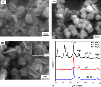
It was found that the concentration of NaOH had a crucial influence on the morphology and structure of the products.Reference Liao, Tannenbaum and Wang28 SEM images in Fig. 2 show the typical morphologies of three samples obtained with different pH value while keeping the other reaction conditions constant. At a low pH value of 10.5, the irregular aggregation was observed in Fig. 2(a). The corresponding XRD pattern shown in Fig. 2(d) indicated that Fe2O3 and Fe3O4 coexisted with FeNi3 crystalline phase. When pH value was increased to 11.5, the relative pure FeNi3 nanoparticles with spherical morphology were obtained as shown in SEM of Fig. 2(b) and XRD pattern of Fig. 2(d). The diameter of the particles was about 20–40 nm. With pH being further increased to 12.5, the product morphology was transformed from spherical to platelet, as shown in Fig. 2(c). Some of the plates interconnected into network structure. There was no other peak except for three peaks at 2θ of 44.3°, 51.5°, and 75.9° in the corresponding XRD patterns in Fig. 2(d) with pH of 12.5, indicating that the platelet particles were the relatively pure FeNi3.
SEM images of the nanoparticles obtained based on ultrasonic method at pH of (a) 10.5, (b) 11.5, (c) 12.5, with 0.16mol/L of N2H4·H2O, and (d) is the corresponding XRD patterns of the particles.

Under alkaline conditions, the standard electrode potential of N2H4 as a reducer is −1.16 V for the electrode reactions of N2H4 + 4OH− → N2 + 4H2O + 4e.Reference An, Pan and Zhang35 Therefore, a basic medium with relatively high pH could improve the reducing power of hydrazine resulting in the relatively pure FeNi3 product. Correspondingly, the metal crystal growth rate was increased in the basic medium.Reference Ni, Zhao, Zhang and Zheng36 However, if the pH of the solution was increased to a certain extent, the trend for Fe(OH)2 and Ni(OH)2 to release Fe2+ and Ni2+ decreased.Reference Liu, Yi, Wang, Qin, Zhang and Li37 The formation of Fe2+ and Ni2+ in the solution became relatively slow, and the iron–nickel crystal growth rate decreased. Also, the growth of [100] planes would be retarded, where the OH− was selectively attached.Reference Shindo, Lee, Waseda, Muramatsu and Sugimoto38 And the iron–nickel crystalline directionally grew along [111] direction and then developed into platelet. It can be seen from Fig. 2(d) that the diffraction intensity ratio I[111]/[200] of the pattern with pH of 12.5 was much higher, implying that the basal planes of nanoplatelets was the [111] facets. Similar results have also been reported for platelet-like fcc metals such as silverReference Chen and Carroll39 and nickel plates,Reference Leng, Zhang, Liu, Suzuki and Li40 possibly because these [111] facets possess the lowest surface energy. The results indicated that the producing rate of nickel and iron atoms can be effectively adjusted by alkali concentration, and thus the aggregation and growth of the Fe–Ni alloy crystallites was kinetically controlled.
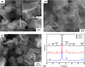
To further investigate the effect of hydrazine on the morphology of the particles, different molar ratio of N2H4·H2O to metallic ions (Fe2+ and Ni2+) was investigated in this work. SEM images in Fig. 3 showed that the morphology of all products were platelet-like with increased molar ratio of N2H4 to metallic ions, indicating that the concentration of hydrazine had little influence on the shape of the particles. The corresponding XRD pattern in Fig. 3(d) indicated that the relatively pure FeNi3 particles can be prepared with increasing N2H4·H2O. When the molar ratio of N2H4·H2O to metallic ions was 2:1, the platelet particles of about 315 nm diameter and 17 nm of thickness were observed [Fig. 3(a)]. Some of the platelets interconnected into edge-curled network-like architecture similar as Ni(OH)2 crystals prepared by microwave-assisted hydrothermal method.Reference Zhu, Wei, Liu and He41 The corresponding XRD pattern shown in Fig. 3(d) indicated that Fe3O4 coexisted with FeNi3 crystalline phase. The edge-curled platelets were observed [Fig. 3(b)] in about 290 nm of diameter and 15 nm of thickness when the molar ratio increased to 3:1. And the reduction was also incomplete, with Fe3O4 coexisting with FeNi3 phase. When the molar ratio was 4:1, the average diameter of the platelet particles decreased to about 96 nm, as shown in Fig. 3(c). The characteristic peaks for FeNi3 were observed in Fig. 3(d), illustrating that 4:1 of N2H4·H2O to (Fe2+ and Ni2+) was capable of completely reducing the metallic ions to produce pure FeNi3 particles. These results indicated that the higher concentration of N2H4·H2O could improve the reducing reaction and result in the relatively pure FeNi3 product.
The SEM images of the nanoparticles with molar ratio of N2H4·H2O to metallic ions (Fe2+ and Ni2+) as (a) 2:1, (b) 3:1, (c) 4:1, and (d) is the corresponding XRD patterns, with 0.75mol/L of NaOH under ultrasonic irradiation.

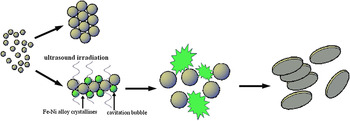
On the basis of experimental results mentioned above, the possible formation processes for FeNi3 platelet structure in our system can be illustrated as in Scheme 1. At an early reaction stage, a lot of bimetallic FeNi3 nuclei were first formed, and then nucleation of primary particles occurred under acoustic fields. These primary particles would aggregate into spherical-like structures, followed by slow, controlled growth through diffusion of molecular-scale species to the surfaces of existing nuclei because of the expansive and compressive acoustic waves resulting in the relatively strong stochastic diffusive force. And then the spheres continued to grow in the [111] direction through an accelerated Ostwald ripening process, i.e., larger particles growing at the expense of smaller particles,Reference Zhu, Xiao, Zhang, Yang and Fu42, Reference Oskam, Hu, Penn, Pesika and Searson43 to form platelet structures under ultrasonic irradiation.
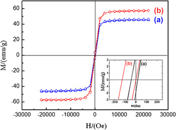
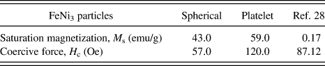
Figure 4 showed room temperature magnetization hysteresis loop with symmetric in shape with respect to zero magnetic field indicating that the samples were ferromagnetic at room temperature. The M s and H c of the spherical and platelet-like FeNi3 particles were listed in Table I. The M s and H c values of spherical FeNi3 particles were about 43.0 emu/g and 57 Oe, respectively, whereas the M s and H c of the FeNi3 platelet nanoparticles reached about 59.0 emu/g and 120 Oe, respectively. This indicated that the FeNi3 platelet nanoparticles showed higher saturation magnetization (almost 1.5 times) and enhanced magnetic coercive force (about 2 times) than spherical ones. The M s value of as-prepared FeNi3 platelet nanoparticles was found to be much higher than that of Ref. Reference Liao, Tannenbaum and Wang28 (about 0.17 emu/g) obtained by hydrothermal reduction process at 180 °C.
Magnetic hysteresis loops of (a) the spherical and (b) the platelet-like FeNi3 particles.

Magnetic data of different FeNi3 particles.
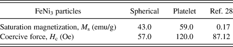
It is known that M s of a magnetic material in an external field is dependent upon the number of magnetic molecules in a single magnetic domain and is proportional to the size of material. Encapsulation layer or surface oxidation at grain boundaries can also result in decrease of M s value of the particles. The smaller M s of spheres (43.0 emu/g) than that of platelet FeNi3 particles (59.0 emu/g) was due to the difference of surface-to-volume ratio and the inevitable slight surface oxidation of the nanoscale subunits, which significantly reduce the total magnetic moments of the spheres.Reference Hausmanns, Krome and Dumpich44 The reason that the M s of sheetlike particles in Ref. Reference Liao, Tannenbaum and Wang28 was smaller than that of as-prepared in this work may be ascribed to the presence of surfactant layer and some surface oxidation of the product.
The H c of magnetic materials depended strongly on shape anisotropy.Reference Diandra and Reuben45 The platelet particles of as-prepared and Ref. Reference Liao, Tannenbaum and Wang28 show higher H c values than spheres due to the relatively higher shape anisotropy of their subunits compared with that in spherical morphology.
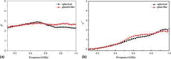
The frequency profile of the complex permeability was shown in Fig. 5. Generally, the real parts of relative complex permeability symbolize the storage ability of electromagnetic energy, and the imaginary parts represent the loss ability. The real part (μ′) of permeability of spherical FeNi3 particles in Fig. 5(a) exhibited a little increase with frequency from 2.10 to 2.87 in the range of 0.1–0.5 GHz, and then decreased to 2.32 within 0.5–1.0 GHz. In contrast, different from the performance of conventional FeNi3 powder materials,Reference Lu, Liang, Sun and Yang46 the real part (μ′) of permeability of FeNi3 platelet particles was about within 2.43–2.71, showing little change with frequency in the range of 0.1–1.0 GHz. And at the same time, the imaginary part (μ′′) of both spherical and FeNi3 platelet particles in Fig. 5(b) both showed a little increase from 0.04 to 2.14 in the range of 0.1–1.0 GHz. The frequency performance of the FeNi3 platelet particles may be ascribed to the dominant shape anisotropy, which is to be investigated next.
Frequency dependence of (a) the real part (μ′) and (b) imaginary part (μ′′) of the initial complex permeability for FeNi3 nanoparticle samples (■) the spherical and (▲) the platelet-like FeNi3 particles.

Illustration of the formation process of the platelet-like FeNi3 particles.

IV. CONCLUSIONS
In conclusion, FeNi3 platelet nanoparticles were synthesized by aqueous reduction at room temperature. Investigation on reaction performance ways indicated that ultrasonic irradiation favored formation of relative pure FeNi3 crystallization with platelet morphology. And the pH value of the solution played an important role to control the structure of Fe–Ni alloys nanoparticles. The morphology of FeNi3 transformed from spherical to platelet with pH increasing from 11.5 to 12.5. The concentration of hydrazine had little influence on the shape of the particles. The as-prepared FeNi3 nanoparticles exhibited typical ferromagnetic properties. The M s and H c of the FeNi3 platelet nanoparticles were about 59 emu/g and 120 Oe, respectively. The real part (μ′) of permeability of FeNi3 platelet was about 2.43–2.71 and was independent of frequency in the range of 0.1–1.0 GHz. The μ′′ of platelet particles showed relatively stable increase from 0.04 to 2.14 with frequency within the same frequency range. This work may provide an additive strategy for the controlled synthesis of bimetallic alloy structures with tunable morphology and magnetic properties.
ACKNOWLEDGMENTS
The authors acknowledge the funding supports from National Natural Science Foundation of China (Nos. 21176005, and 50974006), The Grand Science and Technology Program from Educational Ministry (No. 309008), and Beijing Municipal Natural Science Foundation (No. 2102004). The authors also thank Dr. Zhang Xuehong and Liu Shuzhen for SEM characterization.