Introduction
Wireless communication systems using linearly polarized antennas require strict orientation of it with respect to the transmitting/receiving antenna elements at the other end. A deviation of it results in polarization mismatch and hence the loss of the received signal. The problem becomes severe in the case of satellite communication where the signal undergoes Faraday rotation during propagation through ionosphere. This problem can be avoided by using circular polarization (CP) antennas. Therefore the researchers have given huge efforts to implement circular polarization property in the antennas. As a result a number of CP antennas have been designed. A single fed single band CP antenna is presented in [Reference Herscovici, Sipus and Bonefacic1] using microstrip technology. Antennas having dual band dual CP properties [Reference Bao and Ammann2–Reference Shao and Chen4] are also proposed.
Recently metamaterial (MTM) structures have found huge applications in antenna technology due to its numerous advantages and some unusual properties, not common in nature. They have negative permittivity and permeability, anti-parallel group and phase velocity, and zero propagation constant. Using a composite right and left-handed transmission line (CRLH-TL) the zeroth-order resonance (ZOR) property of an antenna can be achieved. MTM antennas have a priority over conventional antenna due to its small size. The antenna can be arbitrarily miniaturized due to independency of the ZOR frequency on the physical size of the antenna; however distributed lumped parameters are responsible for the ZOR frequency [Reference Caloz and Itoh5]. On the other hand, a ZOR antenna suffers with low gain [Reference Zhou, Wang, Wang, Zong and Ma6, Reference Ko, Park and Lee7], narrow bandwidth [Reference Zhou, Wang, Wang, Zong and Ma6–Reference Cao, Liu, Zhang, Yu and Qian8], and low-radiation efficiency [Reference Zhou, Wang, Wang, Zong and Ma6, Reference Rahimi, Keshtkar, Zarrabi and Ahmadian9]. Several MTM based multiband antennas, such as, CRLH-TL based ZOR multiband antenna [Reference Xing, Li, Zhang, Sun and Shi10], dual-ZOR MIMO antenna [Reference Shi, Zhang and Liang11], and Quad-element multi-band antenna [Reference Li, Shi and Liang12] are reported in the literature. However, a detail survey reveals that MTM antennas with CP property are reported in literatures in less number. Most of these reported antennas have via; hence the fabrication is complicated [Reference Cao, Liu, Zhang, Yu and Qian8]. The 10 dB impedance bandwidth [Reference Zhou, Wang, Wang, Zong and Ma6–Reference Cao, Liu, Zhang, Yu and Qian8] and axial ratio bandwidth (ARBW) [Reference Zhou, Wang, Wang, Zong and Ma6–Reference Rahimi, Keshtkar, Zarrabi and Ahmadian9], [Reference Cai, Wang, Zhang and Shi13–Reference Yi and Qu15] of some of these antennas are also very low.
In this paper two asymmetric co-planar waveguide (ACPW) fed, single layer, CP, and ZOR antennas are presented (Antenna I and Antenna II). The second antenna differs from the first antenna by its band notch characteristics. Both antennas have overall physical dimensions of 26 mm × 20 mm × 1.6 mm. Proposed Antenna-I has a simulated impedance bandwidth of 1770 MHz (3.78–5.55 GHz) with ZOR at 4.65 GHz. By adding a stub on the left side of the ACPW ground, an ARBW of 1750 MHz is achieved in Antenna I. The ARBW almost overlaps with the corresponding impedance bandwidth. Next, the ground plane of Antenna I is further etched with a quarter wavelength slit to implement a notch band from 4.18–4.65 GHz (Antenna II). The notch band isolates the WiMAX and 5.2 GHz bands. An enhanced impedance bandwidth of 2200 MHz (3.28–5.48 GHz) is also achieved. An achieved ARBW of 1080 and 870 MHz in the first and second band of Antenna II almost overlaps with the respective impedance bandwidths.
Antenna realization, analysis, and measurements
In this section both the antennas are presented and discussed along with their measured results. The proposed antennas are designed using ACPW concepts to avoid the design complexity created by the shorted pin (via). Both sides of the ACPW ground and feed line dimensions are modified to achieve desired radiation characteristics and best impedance matching. The antennas consist of a hut-shaped patch, capacitively coupled to a V-shaped feed line. The gap provides the series capacitance of the CRLH-TL. The width of the capacitive gap is 0.3 mm (g 3). The patch is also shorted to the ground plane with a thin folded strip with a thickness of 0.2 mm (t 1). This strip gives the shunt inductance of the CRLH-TL. The antenna structure is shown in Fig. 1. The equivalent CRLH-TL is shown in Fig. 2.
Geometry of the proposed Antenna-I. L = 20, l 1 = 18.15, l 2 = 11.65, l 3 = 10.15, l 4 = 4.05, l 5 = 6, l 6 = 1.6, l 7 = 5.45, W = 26, w 1 = 10.5, w 2 = 7, w 3 = 1, w 4 = 3, w 5 = 2.6, w 6 = 2, w 7 = 11, k 1 = 6.5, k 2 = 3.5, g 1 = 0.9, g 2 = 0.5, g 3 = 0.3, t 1 = 0.2, s 1 = 2.2, s 2 = 2, s 3 = 4.4, s 4 = 1.8, s 5 = 1, and s 6 = 1.2 (unit: millimeters).

Equivalent CRLH-TL.

The simulation and optimization of the antennas have been carried out using HFSS 15 and then both the antennas have been fabricated for measurements. The structures have been implemented on the FR4 substrate with a thickness of 1.6 mm (ɛ r = 4.4, and tan δ = 0.02). Network and radiation characteristics of the fabricated prototype have been measured in an anechoic chamber using an N5221A Keysight PNA to verify the simulation results.
Antenna-I: circularly polarized ZOR antenna
A schematic diagram of the proposed ZOR antenna (Antenna I) is shown in Fig. 1. The antenna is designed using the CRLH-TL approach. Right handed inductance (L R) is realized by the feed line and the radiator. The gap between V-shaped feed and patch gives the left handed capacitance (C L). The folded thin line from the patch to the ground forms the left handed inductance (L L). The gap between the feed line and the ACPW ground provides the right handed capacitance (C R), as shown in Fig. 2. The antenna follows the open ended boundary condition concepts. The ZOR resonant frequency of the antenna (ωZOR) depends on the shunt distributed parameters of the tank circuit and can be calculated using the relation [Reference Jang, Choi and Lim16]
 $$\omega _{sh}\, = \,\omega _{ZOR}\,{\rm}={\rm } \,\displaystyle{1 \over {\sqrt {L_LC_R}}} $$
Figure 3 shows the comparison of the input reflection coefficient with the variation of shunt inductance (L L). The shunt inductance increases with the increase of the length of the thin strip line (any one or more of s 1, s 2, s 3, s 4, s 5, and s 6). According to equation (1), resonant frequency should shift towards left, which is in accordance with Fig. 3.
Comparison of simulated |S 11| (dB) responses of the Antenna-I with different values of s 1.

For open ended case the bandwidth of the antenna is given by [Reference Jang, Choi and Lim16]
 $$BW\,{\rm}={\rm } \,\sqrt {L_L/C_R} $$
With the increase of the length of the thin strip the shunt inductance (L L) increases, hence a significant increase in the bandwidth is also observed. This proves the ZOR property of this antenna. In order to further analyze the ZOR property, the vector field distribution and the surface current density distribution on the patch at the ZOR frequency (4.65 GHz) are shown in Figs 4(a) and 4(b), respectively. Figure 4(a) shows that at ZOR frequency all the vector fields are in phase and perpendicular to the patch. The high surface current concentration on the thin strip (shunt element) at the ZOR frequency establishes the open ended boundary condition concept.
(a) Vector field and (b) surface current density distribution on the antenna at 4.65 GHz.

The dispersion diagram of the proposed structure from the extracted parameters from lumped equivalent circuit is presented in Fig. 5. The extracted values are: L R = 3.59 nH, L L = 9.78 nH, C R = 0.12 pF, and C L = 0.325 pF, which corresponds to f SE = 4.659 GHz and f SH = 4.645 GHz. These are exactly same with the dispersion diagram.
Dispersion diagram shows the ZOR property of the proposed antenna.

In the proposed Antenna-I CP property has been implemented by adding the ground stub of dimensions k 1 × k 2. Therefore parametric analysis of the antenna with k 1 and k 2 is important. The response of the input reflection coefficient and axial ratio (AR) of the antenna with k 1 are presented in Figs 6 and 7, respectively. Figure 6 reveals that the input reflection coefficient and 10 dB return loss bandwidth of the antenna improves with an increase of k 1 and for k 1 = 6.5 mm a second resonance mode appears in the reflection coefficient response. Figure 7 reveals that the 3 dB ARBW is extended significantly towards lower frequency as k 1 increases. Therefore by tuning the value k 1 the AR at the lower frequency can be adjusted.
|S 11| (dB) responses of the Antenna-I with the variation of k 1.

AR response of the Antenna-I with the variation of k 1.

The variation of the input reflection coefficient and AR with k 2 are presented in Fig. 8 and 9, respectively. Figure 8 reveals that with the change of k 2 the matching frequency shifts without changing the 10 dB return loss bandwidth and a second resonance appears when k 2 = 3.5 mm. Figure 9 reveals that with the increase of k 2 the AR is extended towards the higher frequency. So by adjusting the value of k 2 the AR can be tuned towards higher frequency. In this proposed antenna the optimized stub dimension considered is 6.5 mm × 3.5 mm.
|S 11| (dB) responses of the Antenna-I with the variation of k 2.

AR response of the Antenna-I with the variation of k 2.

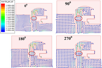
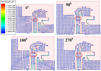
In order to illustrate the generation of the CP mechanism as a result of the introduction of the stub, the time varying surface current distributions at 4.65 GHz on the unloaded and loaded ground stub antennas are presented in Figs 10 and 11, respectively, for four different time phases, ωt = 0°, ωt = 90°, ωt = 180°, and ωt = 270°. A comparison of the figures reveals that the introduction of the ground stub changes the ground surface current distribution, which, in turn, effects the surface current distribution on the radiator patch. The comparison also reveals that as a result of the above surface current changes a clockwise rotation of surface current is introduced on the radiator (marked by circle in Fig. 11), which is absent in Fig. 10. The E x/E y plot and the corresponding phase plot for the above two cases are shown in Fig. 12. It reveals that in the latter case the radiated field is broken into two orthogonal components with approximately equal magnitude and −90° phase shift. This results in left handed circularly polarization (LHCP) in the +z direction and right handed circularly polarization in the −z direction.
Vectored surface current distribution on the antenna with an unloaded ground stub at 4.65 GHz at ωt = 0°, 90°, 180°, and 270°.

Vectored surface current distribution on the antenna with a ground stub at 4.65 GHz at ωt = 0°, 90°, 180°, and 270°.

E x/E y ratio of the radiated field of the antenna with and without the ground stub (a) amplitude ratio and (b) phase difference.

Fabricated prototype of the proposed antenna is shown in Fig. 13. Simulated and measured input reflection coefficients of the antenna are shown in Fig. 14. The figure reveals that the simulated and measured 10 dB return loss bandwidth are 1770 MHz (3.78–5.55 GHz with fractional bandwidth (FBW) = 37.94%) and 2310 MHz (4.13–6.44 GHz with FBW = 43.7%), respectively. Little discrepancies between the simulated and measured results are observed due to the parasitic effect of the connector soldering.
Photograph of the fabricated prototype I.

Simulated and measured |S 11| of the Antenna-I.

In Fig. 15 simulated and measured ARs are presented. It reveals that the simulated ARBW is 1750 MHz (3.50–5.25 GHz) and the measured ARBW is 1560 MHz (3.58–5.14 GHz). To measure the axial ratio, a broadside radiation direction of the test antenna is kept facing toward the horn antenna (WR229 and WR187) in the far field region. Then the horn is rotated by 10° at the plane of polarization and the corresponding received power (in dB) is recorded. By subtracting the maximum and minimum power in each particular frequency the axial ratio is calculated in the desired frequency range.
Simulated and measured AR of the Antenna-I.

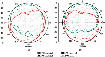
Simulated and measured peak realized gains and the simulated radiation efficiency of the proposed Antenna-I are plotted in Fig. 16. Achieved simulated and measured peak realized gains are 2.61 and 2.08 dBic, respectively, at 4.65 GHz. The high simulated radiation efficiency of 95.72% is achieved at the frequency of operation. Figure 17 shows the simulated and measured normalized RHCP and LHCP radiation pattern of the Antenna-I. The figure reveals that the antenna radiates LHCP wave in the +z direction and RHCP in the −z direction.
Simulated and measured peak realized gain and simulated radiation efficiency of the proposed Antenna-I.

Simulated and measured normalized RHCP and LHCP patterns (a) xz-plane and (b) yz-plane at 4.65 GHz.

Antenna-II: CP ZOR antenna with band notch characteristics
Proposed Antenna-II is a band notch antenna which is a modified version of antenna I, keeping the physical dimensions same. Figure 18 presents the modified antenna structure, which incorporates a thin slot of dimensions l 8 × g 4 on the ground plane. This forms nearly a quarter wavelength slit which resonates at 4.45 GHz and creates a band notch at this frequency. The photograph of the fabricated prototype is shown in Fig. 19.
Structure of the proposed Antenna II: L = 20, l 1 = 18.15, l 2 = 11.65, l 3 = 10.15, l 4 = 4.05, l 5 = 6, l 6 = 1.6, l 7 = 5.45, l 8 = 7.6, W = 26, w 1 = 10.5, w 2 = 7, w 3 = 1, w 4 = 3, w 5 = 2.6, w 6 = 2, w 7 = 11, g 1 = 0.9, g 2 = 0.5, g 3 = 0.3, g 4 = 0.5, t 1 = 0.2, s 1 = 2.2, s 2 = 2, s 3 = 4.4, s 4 = 1.8, s 5 = 1, and s 6 = 1.2 (unit: millimeters).

Photograph of the fabricated prototype II.

Figure 20 shows the simulated and measured input reflection coefficient of the Antenna-II. The figure reveals that the antenna has a simulated 10 dB return loss bandwidth of 2200 MHz (3.28–5.48 GHz) with a notch band from 4.18–4.65 GHz. The measured 10 dB return loss bandwidth of the antenna is 2430 MHz (3.21–5.64 GHz) with a notch band from 3.94–4.61 GHz. The frequency shifting may be caused by the effect of the parasitic at the soldering joint.
Simulated and measured input reflection coefficient of Antenna II.

The surface current distribution in Fig. 21 shows that at 4.45 GHz the slit draws the maximum current around it and restricts the patch to radiate; hence the notch band is created. The impact of the variation of l 8 on the input reflection coefficient is presented in Fig. 22. It reveals that with the decrease of the slit length l 8, the notch frequency shifts towards higher frequency. This is because with a decrease in the length its electrical length (≈0.25λ g) also decreases and hence it resonates at higher frequency. So by adjusting the length l 8 the notch band can be tuned at the desired frequency.
Surface current (magnitude) distribution at 4.45 GHz.

Input reflection coefficient of Antenna-II with the variation of l 8.

Simulated and measured ARs of the antenna are presented in Fig. 23. The figure reveals that the simulated 3 dB ARBWs of the antenna are 1080 MHz (3.41–4.49 GHz) and 870 MHz (4.62–5.49 GHz), respectively. The 10 dB return loss and 3 dB AR overlapping bandwidths are 770 and 830 MHz for the lower and upper band, respectively. The lower and upper CP bands are separated by 110 MHz (4.50–4.61 GHz). Measured 3 dB ARBWs of the antenna are 980 MHz (3.64–4.62 GHz) and 850 MHz (4.68–5.53 GHz), respectively.
Simulated and measured axial ratio of Antenna-II.

Simulated and measured peak realized gains and simulated radiation efficiency of the antenna are plotted in Fig. 24. Achieved simulated peak realized gains are 2.38 and 2.97 dBic at 3.7 and 5.1 GHz, respectively. Corresponding measured peak realized gains are 1.77 and 2.35 dBic, respectively. High simulated radiation efficiencies of 95.24 and 93.07% are obtained at both the bands, respectively.
Simulated and measured peak realized gain and simulated radiation efficiency of the proposed Antenna-II.

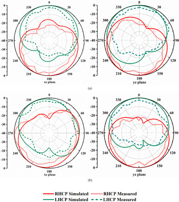
Normalized simulated and measured RHCP and LHCP radiation patterns of the antenna on both orthogonal planes at 3.7 and 5.1 GHz are presented in Fig. 25. It is evident from the patterns that the antenna has a bidirectional radiation pattern with the LHCP wave at the +z direction and RHCP wave at the −z directions.
Simulated and measured normalized RHCP and LHCP patterns of the Antenna-II in xz- and yz-planes at (a) 3.7 GHz and (b) 5.1 GHz.

Some of the characteristics of the proposed Antenna-I and Antenna-II are compared with some previously reported CP MTM antennas in Table 1. It is self-explanatory.
Comparison of Antenna-I and Antenna-II with some previously reported CP antennas

a Notch at 4.18–4.65 GHz.
Conclusion
In this paper two ACPW feed ZOR antenna prototypes have been presented using a CRLH-TL approach. Antenna-I has a measured impedance bandwidth and ARBW of 2310 and 1560 MHz, respectively. This antenna offers a moderate peak realized gain of 2.61 dBic and a radiation efficiency of 95.72%. In Antenna-II a notch band is created to isolate WiMAX and WLAN bands. The measured impedance bandwidth is 2430 MHz with a notch band from 3.94–4.61 GHz. Measured ARBWs are 980 MHz (lower band) and 850 MHz (upper band). Measured peak realized gains of Antenna-II are 1.77 and 2.35 dBic at 3.7 and 5.1 GHz, respectively. Corresponding simulated radiation efficiencies are 95.24 and 93.07%. Comparison of the characteristics of the proposed Antenna-I and Antenna-II with some previously reported antennas reveals that the proposed antennas have better radiation characteristics than others, except the gain of some antennas.
 Kalyanbrata Ghosh currently pursuing his PhD in the Department of Electronics Engineering, Indian Institute of Technology (Indian School of Mines), Dhanbad, India. He has a teaching experience of more than 10 years. He received his M.Tech and B.Tech in 2008 and 2006 respectively. His current research interests focus on the development of wide band circularly polarized metamaterial antennas.
 Sushrut Das received BSc, MSc, MTech, and PhD degree in 1999, 2001, 2003, and 2007 respectively. He joined Indian Institute of Technology (Indian School of Mines), Dhanbad, India, in the year 2007. He is currently working as an associate professor in the Department of Electronics Engineering. He has authored one book, Microwave Engineering (Oxford University press, 2014) and published several research papers in referred international journals. He has received URSI (International Union of Radio Science) Young Scientist Award in Istanbul, Turkey. His research interests include microwave antennas, microwave passive structures, wireless energy transfer, and energy harvesting.