I. INTRODUCTION
In the recent literature several strategies for applying orthogonal frequency division multiplexing (OFDM) waveforms as radar signals for various purposes are under investigation. As in [Reference Donnet and Longstaff1–Reference Garmatyuk, Schuerger, Morton, Binns, Durbin and Kimani4], multi-carrier signals such as OFDM allow for flexibility and efficient use of the spectral resources. Furthermore, when considering the simultaneous use of waveforms for both radar and communication a large time-bandwidth product allows for sufficient data rate [Reference Fens, Ruggiano and Leus5].
Traditionally target detection schemes were based on optimizing the signal-to-noise ratio (SNR) of point targets embedded in additive white Gaussian noise (AWGN). On the other hand modern radar systems, such as the OFDM-based one, have to confront themselves with the detection of closely spaced targets with large power ratios between strong and weak reflectors. Consequently the closely spaced targets interfere with each other, and applying the standard matched filtering technique causes masking of the weaker close targets by the range sidelobes of the stronger target. Nevertheless such matched filtering techniques are optimal [Reference Di Franco and Rubin6], maximizing the output SNR: often the desired targets are weak, and for their detection it is crucial to achieve the highest possible SNR at the output of the filter.
Several coding schemes [Reference Levanon and Mozeson2] have been analyzed to counteract the inherent high sidelobe level of OFDM when processed by a matched filter (MF). Nevertheless, the desire for communication data embedded in the OFDM radar waveform precludes the adoption of rigid coding schemes to lower the sidelobes. Consequently, the load of lowering the sidelobes is shifted to the receiving filtering scheme. The main concern is then to evaluate the difference with respect to the MF output in terms of SNR.
Sidelobe suppression schemes such as the CLEAN algorithm [Reference Chang and Bell7] were compared in [Reference Blunt and Gerlach8, Reference Ruggiano, Stolp and van Genderen9] with other filtering techniques [Reference Blunt and Gerlach10] proposed to resolve closely spaced targets, based on linear minimum mean square error (LMMSE).
The objective of this paper is to analyze the theoretical SNR performance of the reiterated LMMSE-based filter in comparison with the MF, and to evaluate its performance when applied to the OFDM radar–communication waveform. Moreover this performance is assessed by the comparison to the one obtained when processing P3 signals instead.
This paper is an extended version of [Reference Ruggiano, Stolp and van Genderen11] and is structured as follows. In Section II the multi-carrier radar/communication waveform OFDM signal is presented and clarified. Section III provides the description of the reiterated LMMSE filtering algorithm. In Section IV the theoretical performance of the LMMSE is derived. The simulation results are described in Section V. Conclusions are presented in Section VI.
II. OFDM RADAR–COMMUNICATION WAVEFORM
Among the multi-carrier signals, OFDM has wide success as it possesses the same spectral efficiency of a single carrier waveform, allows increased spectral flexibility, and can be easily implemented with fast Fourier transforms [Reference Proakis12].
The OFDM baseband chip can be expressed as follows:
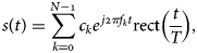
where N is the number of carriers, T is OFDM symbol duration, f k is the kth carrier center frequency, c k is the code symbol mapped on the kth sub-carrier on the OFDM symbol, and rect(t/T) is the rectangular window of duration T and unit amplitude. The carrier spacing Δf is equal to the inverse of the OFDM symbol duration: the carriers are orthogonal.
Expressing the OFDM chip in (1) in discrete form, recalling that f k is the product of k and Δf, and sampling at Nyquist frequency f s = N/T leads to

The N samples in (2) can be expressed in compact form as a vector, indicated with s. The communication information encoded symbols c k, k = 1, … , N, can vary from OFDM symbol to OFDM symbol because they represent the encoded message to be transmitted. Consequently, it is not possible to restrict the selection of a set of c k, k = 1, … , N, to produce low sidelobes at reception with an MF. Modified filtering techniques are then necessary, as described in the following section.
III. LMMSE FILTERING SCHEME
Some alternative techniques to traditional matched filtering belong to the least squares type. These last aim at minimizing the square error, either as model matching error or as output error. When placing such techniques in a statistical approach, the aim is to estimate the filter obtaining the minimum of the mean square error (MMSE). The theoretical Wiener filter is based on the MMSE. To improve its analytical tractability the assumption of a linear model for the received signal (linear estimator) can be applied, leading to an LMMSE technique [Reference Kay13]. The novelty introduced by [Reference Blunt and Gerlach10] consists in applying such an LMMSE scheme in a reiterated way on a reducing subset of the same sequence of samples of the received signal, with no fresh samples added.
A) Data model
The data model describes the received signal in terms of its components due to the transmitted signal and noise. When considering N range bins, out of a total of L, the length of the processing window, we obtain the following expression for the received signal:

where index n indicates the nth range bin, ỹ(n) is the received signal vector of N samples, from the n-th range bin to the n+N−1 range bin, s is the transmitted signal with unitary energy,  is a vector containing N samples of the thermal or AWGN and AT(n) is the matrix used to operate the discrete convolution between the target range profile and the transmitted signal. It contains the complex-valued target range profile for a length of N range bins, shifted on each row. It is a square matrix of dimension N; the superscript T indicates the transpose operation, just as H indicates the hermitian operation. The received signal and target profile convolution matrices are given below, and analogously the transmitted signal and the noise vector:
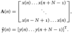
B) Filtering at the receiver
The filter to be applied at the receiver on the received sequence in (3) is generated by the MMSE cost function on the output of the filter:

The estimated optimal filter w(n) with respect to the criterion in (4) [Reference Moon and Stirling14] is a form of the Wiener filter:

With the received signal model in (3), the filter can be rewritten as

where  .
In the hypothesis that the target profile samples are uncorrelated and equal to their realization, (6) becomes

with  , and sq contains the elements of s shifted by q samples and the remainder zero-filled, i.e.
 . Since the true target profile x(n) is not known, as in [Reference Blunt and Gerlach10] the procedure is applied iteratively to obtain a better estimate on the central sequence of samples in the processing scheme, and the filter in (7) is generated iteratively:

where the notation indicates with the subscript m the mth iteration. The filter output at the mth iteration is

where the target profile at range bin n and at iteration m is given by the filter output at the previous iteration, m = 0, … , M−1. As in the algorithm in [Reference Blunt and Gerlach10], the matrix inverted in (7) is obtained by considering it equal to the sum of the noise covariance matrix, considered known, and E{AT(n) s sHA*(n)}, assuming that target profile realizations are uncorrelated. The initialization is simply given by the MF output:

IV. THEORETICAL PERFORMANCE OF THE REITERATED LMMSE-BASED FILTERING
In order to evaluate the characteristics of a reiterated LMMSE scheme, it is necessary to compare it to the MF, which is the reference for the single target case [Reference Di Franco and Rubin6].
In the statistical framework [Reference Therrien15], allow the following assumptions: a single target in range bin n, x(n) drawn from a random distribution; AWGN vector  s.t. b(n) ~ CN(0, σb2), with n = 0, … , N − 1; the true target profile and noise samples are uncorrelated without loss of generality, i.e.
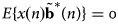 . The two hypotheses [Reference Kay13] for the absence and presence of a single target can be indicated as

Assume now that the filter in (5) is generated with an estimated target profile that is not equal to the true target profile alone but also contains an error term. The estimated target profile at iteration m can then be written as

where δx (m)(n) is the error term at iteration m. The filter estimated in (5) now becomes, respectively, in the two hypotheses


In expressions 13 and 14 of the filter, new terms are visible due to the error in the estimated target profile used for the generation of the filters.
Using (13) and (14) to filter the received signal leads to an output that is an estimate of the target range profile, just as when applying the MF on the received signal as in (9) and (10). Since the target profile in this context is described in a statistical manner, define the mean and the variance of the filters' output. For H 0, the mean is zero and the variance of the output is

For the case of target present, the mean of the output is

and the variance of the output is
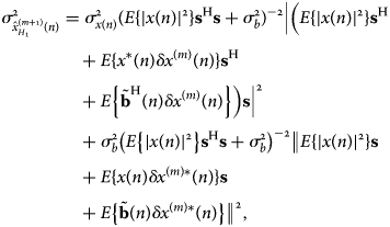
where ‖v‖2 = vHv for a generic vector v. It is interesting to consider the LMMSE filter when initialization is done with MF output: from (12) the error term becomes

The first two terms of the sum to the right of the equal sign in (14) become, respectively, in this case
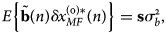

due to the hypothesis of target and noise being uncorrelated. By substituting (19) and (20) in (13) and (14), (13) and (14) reduce to

Consequently, the LMMSE reiterated scheme as in (13) and (14), initialized with the MF output, reduces to the MF itself in the case of a single target, and therefore maximizes the SNR just as the single-stage MF does, without loss. In the case of target present, the SNR ratio at the output of the LMMSE filter in (21) is, for every m,
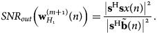
But (22) is obviously equal to the SNR for the output of MF.
In the context of a stochastic approach it is appropriate to define the mean SNR at the output of a generic filter f in terms of the ratio of the expected values of the signal echo and the expected value of the noise component:
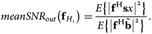
Computing the mean SNR at the LMMSE filter (14) output with initialization error as in (18), as in (21), gives for every m

Expression (24) is also valid for the MF output mean SNR.
In this statistical framework consider now derivations for the variance of the SNR. The variance of the SNR is as usual defined as

where, for a generic filter f, SNR out and meanSNR out is as given by (23). It is possible then to express (25) for the SNR in (22), given the before mentioned hypothesis of statistically independent noise samples and noise and target uncorrelated, together with
 . Consequently, the following expression holds:
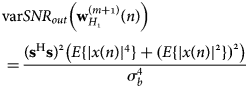
is also valid for the MF output, in the same hypotheses of noise and single target assumed to be statistical while transmitted signal deterministically known.
It is also relevant to address the aspect of linearity of the filtering method. This property is important as it allows inverting the order of operations. This is of particular interest for processing schemes that include both range and Doppler processing [Reference Skolnik16].
When evaluating the linearity of the scheme, these two properties should be verified. In the following two equations, it is clearly shown how the filtering process still exhibits a linear property due to linearity of the convolution operation:


where ỹ1(n) and ỹ2(n) are two arbitrary received signals, α is an arbitrary scalar, and m is the iteration number.
It is interesting to mention that, depending on the received signal strength and the number of targets, the filter wH(n) will be different. For example consider the received signals in (27a), either on the left or on the right of the equal sign: the filter wH(n) will be different in the two cases in which only ỹ1(n) is present or both ỹ1(n) and ỹ2(n) are present. This can be easily related to (5), which indicates the expression for filter generation: (5) shows the dependency on ỹ(n), whether it is ỹ1(n) or ỹ1(n) + ỹ2(n) as in the example above. It is then important to note that in the presence of multiple targets coherency is lost when processing a train of pulses to extract Doppler. Consequently, Doppler processing should be done before the unmasking algorithm.
V. SIMULATION RESULTS
In the previous section the theoretical performance of the reiterative LMMSE is derived and compared with the MF for the single-target case. In this section plots are shown for various parameters in the single-target case for the outputs, respectively, of the MF and the LMMSE filter with MF initialization. Simulations are obtained for coded signals such as P3 codes and OFDM signal.
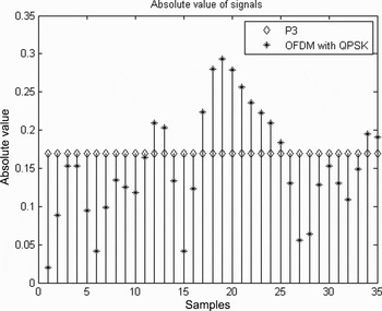
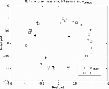
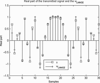
The P3 signal [Reference Lewis and Kretschmer17] is a discrete form of a linear frequency modulated signal, often used as a radar waveform, and can consequently be assumed as a benchmark. Its baseband expression is s(p) = e jπp 2/N, p = 0, … , N − 1. Here a P3 signal and an OFDM signal with quadrature phase shift keying (QPSK) coded symbols, N = 35 samples, are considered, M = 7 and L = 100 range bins. In Figs 1 and 2 the two coded waveforms are shown, the OFDM signal and the P3 signal, respectively, in the complex plane and in the absolute value. It can be easily seen how the OFDM signal with QPSK symbols presents a spiky and noise-like time evolution. Consider the result obtained in (21) and (22). For conciseness only w in H 0 is shown. Figure 3 gives w, computed as an average over all range bins, and s in the complex plane, for a P3 signal for ease of visualization, since the samples of s lie on a circle. Figure 4 shows the same signals in their time evolution: the real part of both signals is shown sample by sample.
P3 and example of OFDM signal in time domain on complex plane.

Absolute values of P3 and example of OFDM signal in time domain.

LMMSE filter and MF filter on the complex plane; P3 signal.

LMMSE filter and MF filter time-evolution; P3 signal.

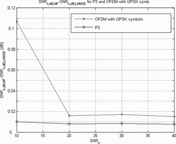
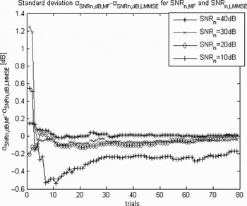
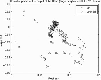
The average output SNR, for an energy normalized signal (SNRn), achieves for both MF and LMMSE filters the signal-plus-noise to noise ratio. The ratio of the average output SNRn of the two filters is given in Fig. 5 for OFDM and P3 signals; for P3signals the ratio reaches 0.008 dB for large SNRn. The convergence of the ratio of the standard deviation of the output SNRn of the two filters for OFDM can be seen in Fig. 6; for P3 signals the ratio is of the order of 10−3 dB for large SNRn. Figure 7 shows in the complex plane the complex-valued peak at the output of the filters for target amplitude of 3.16 with 120 trials.
SNRn difference for LMMSE and MF filters.

Standard deviation difference of SNRn for LMMSE and MF; OFDM.

Peak outputs in complex plane; OFDM, 120 trials.

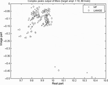
Analogously Fig. 8 shows the complex-valued output of the filter for a target amplitude of 10 with 80 trials. Note that each simulation trial presents randomly picked complex-valued noise samples. In both these last two plots it is possible to view how the outputs of the LMMSE conform to the outputs of the MF.
Peak outputs in complex plane; OFDM, 80 trials.

VI. CONCLUSIONS
It is well known how radar performance is related to the probability of correct detection and false alarm. It has been shown by early radar literature how matched filtering achieves optimal radar performance. This is due to the property of MF of maximizing the output SNR. The MF output peak retains information about the target and it can be used for detection and classification. Nevertheless, the MF output also has sidelobes that can cause the masking of close-by weaker targets. The mis-matched filters offer instead better unmasking capabilities at the expense of SNR loss and degraded performance. When evaluating a filtering scheme, the challenge of improving target unmasking without SNR loss while maintaining nominal resolution is crucial. No SNR loss for actual applications translates into a deviation hardly measurable in practical systems. It is also important to verify that the filter output still represents the signal-plus-noise to noise ratio, as in the MF, for the output peaks to be used for target classification. This last condition translates in filter output peaks conforming to to the MF output peaks.
In this paper the performance of the reiterated LMMSE filtering technique is considered. Evaluating the theoretical performance of the LMMSE filtering technique for a single target and for no target, it was shown that when the input to the LMMSE initialization is the MF output, a closed expression is derived for the error on the target profile estimate. This leads to two consequences: in the mean the LMMSE filter reduces to the MF and in the mean the SNRs at the outputs of the MF and LMMSE are equal in the single-target case. Simulation results prove such performance. In particular in the mean the SNRs at the outputs of the MF and LMMSE are approximately equal, with the discrepancy hardly measurable in practical systems. Moreover, the complex output peaks of the LMMSE filter appear to be in conformity with those of the MF. Results are addressed for coded waveforms such as OFDM and P3, but their validity is not limited to these.
Future research work will target including in the model realistic propagation and target effects, and robustness against electronic impairments. This is an important step in evaluating this processing scheme since it is a model-based type of technique: it relies heavily on the correspondence between the model and the actual received signal generation.
ACKNOWLEDGEMENTS
This project received research funding from the Early Stage Training action in the context of the European Community's Sixth Framework Programme. The paper reflects the authors' views, and the European Community is not liable for any use that may be made of the information contained herein.
 M. Ruggiano received her Master of Science degree in telecommunications engineering at the University of Florence, Italy, in 2005. Her specialization was in transmission, and thesis work on satellite payload advanced resource management. She is currently doing a Ph.D. study in signal processing at the Delft University of Technology, The Netherlands. She was awarded the Socrates-Erasmus Scholarship at the Royal Institute of Technology in Stockholm, Sweden, for 1 year in 2002. She has been working at “European Space Agency Research and Technology Center” (ESTEC), within the “European Satellite Communication Network of Excellence” (SatNEx), under a “Centro Nazionale Interuniversitario per le Telecomunicazioni” (CNIT), contract for half a year in 2004. She was granted the 3-year Marie Curie Fellowship within the Sixth Framework Programme of the European Union, in Delft, The Netherlands, from 2006 to 2008. She has been working for Thales Nederland in the Surface Radar Unit, in Delft, The Netherlands. Her interests are in the communications and radar domains. She received the best paper award at the European Radar Conference in 2008. She also received Agilent's University Innovation Award in 2008.
 Emiel Stolp received his Master of Science degree in physics and mathematics in 1984 at the Free University in Amsterdam on a thesis on wave propagation in an atmosphere with wind and density gradients. In 1985 he joined Hollandse Signaalapparaten BV in Hengelo, The Netherlands, now Thales Nederland. He has been working in the R&D department on radar signal processing, detection, performance analysis, and ECCM processing. At the European Radar Conference (EuRAD) in 2004, he organized a special exhibition on the subject “100 Years of Radar”; in the 2008 conference he was EuRAD secretary.
 Piet van Genderen received his Master of Science degree in electrical engineering from the University of Twente in Enschede, The Netherlands, in 1971. His thesis was in information theory. After graduation, he joined the National Aerospace Laboratory in Amsterdam, The Netherlands until 1979. Since then he has been working with Hollandse Signaalapparaten BV in Hengelo, The Netherlands, now Thales Nederland. He held several positions in R&D as Group Expert Radar Systems. In 1994 he was appointed full professor at the International Research Centre for Telecommunications and Radar of the Delft University of Technology, The Netherlands. He has (co-)authored over 160 papers, seven patents, and a few books. His current research interests are in radar management, adaptable waveforms, and false target recognition. Prof. van Genderen is Member of the European Microwave Association. He has been awarded twice (as author/co-author) with the Radar Prize of the European Radar Conference (EuRAD), has received the prize for the most innovative and effective patent of the Thales group in 2000, and received an honorary doctorate of the Military Technical Academy of Romania. He has been the general chairman of the European Microwave Week in 2004 and the chairman of the European Microwave Conference during this event. He has been a member of the technical program committee of many international conferences dedicated to radar.